

Page 1

Pub. 42004-697L2B
GAI-TRONICS® CORPORATION
A HUBBELL COMPANY
Model 7085-005-UL and 7085-005-EX
SmartSeries Multi- Party Hazardous Ar ea
Amplifi er Enclosures with RTU Cont rol
Confidentiality Notice
This manual is pr ovided s olely as a n op erat ional, installation, and maintenance guide and contains sens itive
bus ines s and t echnic al infor ma tion tha t is confident ial and prop rieta ry to GAI - Tr onic s. GAI- Tr onic s retains
all intellectual prop erty a nd other r ights in or to the information contained herein, and s uch infor ma tion may
only be used in connection with t he op erat ion of your GAI-T ronics produ c t or s ystem. This manu al may not
be disclos ed in any form, in whole or in pa rt, direct ly or indirectly, t o any third party.
General Information
The Model 7085-005-UL and 7085-005-EX Multi-Party Remote Terminal Unit (RTU) Amplifier
Enclosures are components of the 700 Series Page/Party< system. T h ese encl osures are configured f o r
multi-p arty system, which can accommodat e conversa tions on up to five part y lines simulta neou sly. They
are constructed of ca st a l uminum and a re extremely weather proof and cor rosion- resis tant. These
enclosures are equipp ed with termina l str ips for connecting s ystem cable. T he Model 709-901 SmartSeries
Amplifier mates directly with this enclosure.
®
When connected to a SmartSeries system, t he s tat ion opera tes as a standard mult i- party Page/P arty
device. In addition, it supports supervised input circuits and a relay output (supervision optional). The
following configurations a re possible:
• 1 supervised input circuit and 1 supervised relay output (factory setting)
• 2 supervised input circuits and no relay output
• 2 su p ervised inpu t circ uits and 1 non-s upervised relay ou tput
N
OTE: The relay output circuit is intended to be used with GAI-Tronics-approved equipment. The circuit
may not support supervision of equipment that is not approved by GAI-Tronics.
Models 7085-005-UL and 7085-005-EX differ in design by their conduit or c able entries. The Model
7085-005-UL Enclosure contains NPT threads and the Model 7085-005-EX Enclosure contains metric
threads.
GAI-Tronics Corporation P.O. Box 1060, Reading, PA 19607-1060 USA
610-777-1374 800-492-1212 Fax : 610-796-5954
ISIT WWW.GAI-TRONICS.COM FOR PRODUCT LITERATURE AND MANUALS
V
Page 2

Pub. 42004-697L2B
Model 7085-005-UL/ E X SmartSeri es Multi-Par ty Haz. Area Amp. Encl osure wit h RTU Page
Installation
These enclos u res must be inst alled by trained, qualif ied and
competent personnel. I nsta llation mus t comply with s tat e and
national regulations, as well as safety practices for this type of
equipment.
2 of 15
CAUTION
Do not install this e quipment in
hazardous areas other than those indicated on the approval
listing in the Specifications section of this manual. Such
installation may cause a safety hazard and consequent injury
or property damage.
The mounti ng loc ation must be flat and pr ovide p roper
clearance, rigidity and strength to support the enclosure and all
contained devices. The enclosu res a re equipp ed with fac toryinstalled hinges. The enclosures shou ld be mounted with hinges
on the left.
WARNING
Do not mount the enclosu re with hinges
on the top or bottom side.
Securely fasten the enclos ure to the mounting location, using
1/ 2-inch diameter steel mounting bolts a nd wash ers , or washer
head bolts.
WARNING
Do not disconnect equipment while energized.
Insure proper grounding to protective earthing.
Figure 1. The Model 7085-005-UL/EX
Inspect and c lean the machined flange fla me joint sur f aces of both the cover and b ox. Surfaces must be
smooth, f ree of nicks, scrat c hes , dirt or any foreign p article build-up that wou ld prevent a pr oper seal.
Surfa c es must seat fully aga inst ea c h other to provide a prop er explos ion- proof joint. C l ean surfaces by
wiping with a clean lint-free cloth.
Apply a light coat of Killa rk “LUBG” lub rica nt to flange surfac es and close t he cover. Ins tall and tight en
all cover bolts to 30 f t.-lb s. M ake cert ain no cover bolts are omitt ed. Use only thos e b olts supplied with
the enclos ure.
When installing an add-on st ation, consu lt the appr opriate sys tem layout diagrams. These figu res, when
used in conju nction with t he s tat ion insta llation information and ca b l e layout gu ide, should p rovide all t he
information necessary t o insta ll additional Pa ge/ Party< stat ions.
\\s_eng\gtc proddoc s \ s t andard iom s - current release\42004 inst r. m anuals \ 42004-697l2b. doc
11/07
Page 3
Pub. 42004-697L2B
Model 7085-005-UL/ E X SmartSeri es Multi-Par ty Haz. Area Amp. Encl osure wit h RTU Page
3 of 15
Enclos ure Placement
All GAI-Tronics Pa ge/ Party® units are wired in parallel. G ood system layout design minimizes the cable
required for ea ch insta llation. GAI-Tronics multi-condu c tor cable, des igned especially for this applic ation,
is rec ommended. For the numb er, s iz e, and color-coding of c onductors refer to the approp riate system
connection diagra ms .
®
System layout and power c able length are ver y important when inst alling Page/Party
equipment.
Although it vari es f or differ ent systems, the general guideline is t hat t he t otal p ower cable length should not
exceed one mile (5280 feet) for 120 V ac systems. The total cable length is the most important
consideration while cable length between the sta tions is generally not a fa c tor.
Hardware Configuration
External
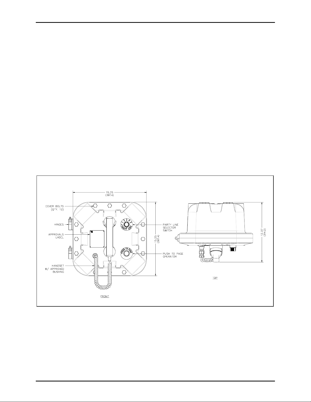
The multi-party enclosur es each contain a handset with an approved gland, push- to-page operator , a party
line selector switch, and ap plicable app roval labeling. The handset rests on a c radle, whic h has a magnetic
reed switc h loc ated behind it to signa l an off-hook c ondition. The enclosure itself has 12 cover mount ing
bolts loc ated a round t he p erimeter of the enclosure, a nd a set of aluminum hinges located on the left side.
See Figu re 2.
GAI-T R ONICS COR P ORATIO N
P.O. BOX 1060 READING, PA 19607
NO USER SERVICEABLE PARTS INSIDE.
REFER SERVI CING TO QUAL IFIED PERSONNE L ONLY.
GAI-TRONI CS SERVICE CEN TERS
Outside USA: 1-610-777-1374In USA: 1-800-492-1212
Figure 2. Model 7085-005-UL/EX Outline Drawing
\\s_eng\gtc proddoc s \ s t andard iom s - current release\42004 inst r. m anuals \ 42004-697l2b. doc
11/07
Page 4
Pub. 42004-697L2B
Model 7085-005-UL/ E X SmartSeri es Multi-Par ty Haz. Area Amp. Encl osure wit h RTU Page
Internal
4 of 15
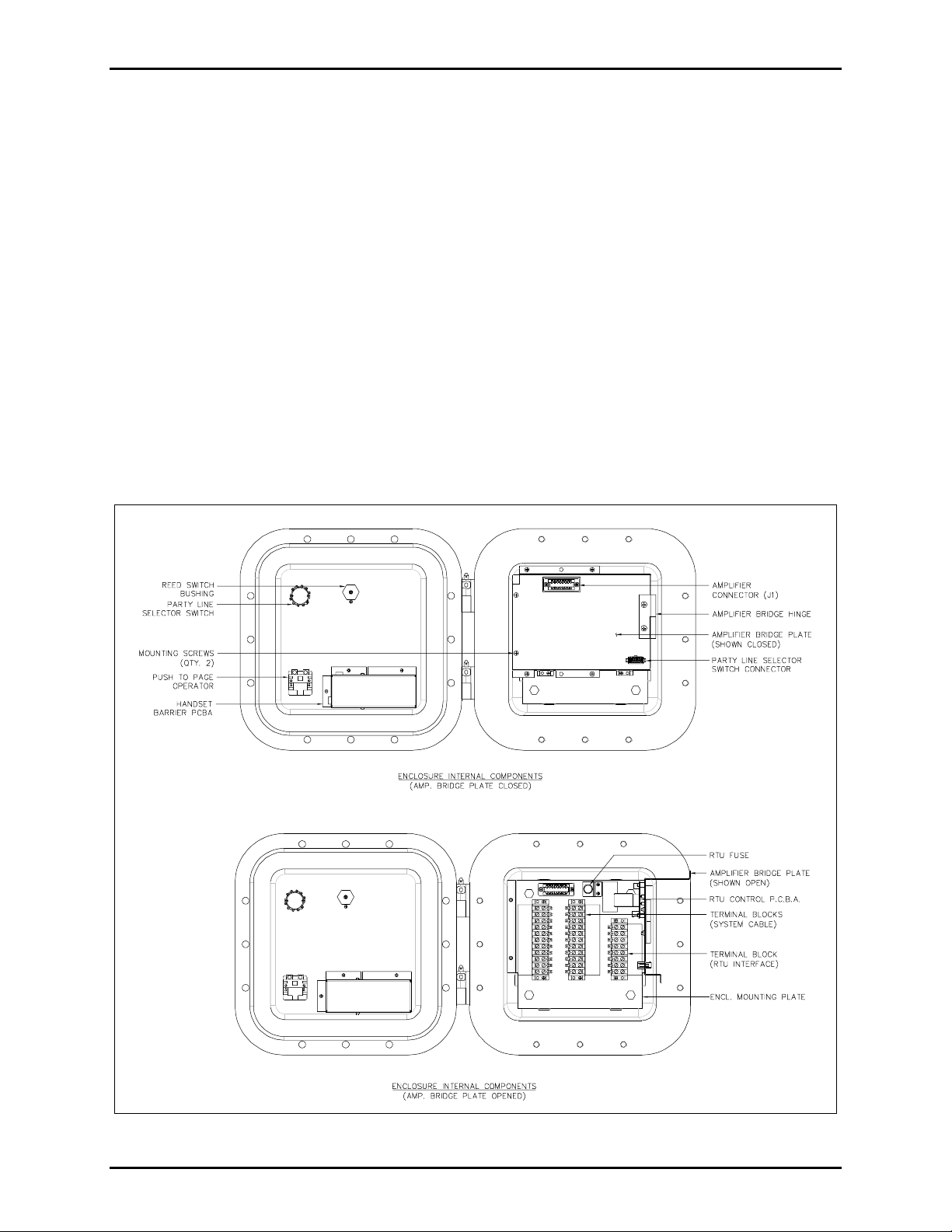
The multi- party enclosures contain three ter mina l blocks, an int erior mount ing plat e, an a mp lif ier br idging
plate, a nd a connect or for the mating M odel 709-901 Amplifier. The amplifier bridging plate is hinged on
one side and attached on the opposite side with two #10-32 screws. For system cable installation, the
screws to t his pla te must be removed and the b ridging plate swu ng open 90º. Upon installation of the
wiring cable, the amplifier bridging plate can be rotated closed and reattached with the two #10-32 screws.
This plat e will then serve as a pr otection for the amplifier and t he switches fr om the s ystem cable when the
unit is complet ely closed. Refer to Figure 3.
The RTU cont rol adds an a dditional 8-point terminal block, f use holder wit h insta lled f u se, a nd RTU
contr ol PCBA. These it ems are mounted t o the interior mounting p late a nd b ackside of the amplifier
bridging plate. Care s hould be taken to keep wir es out from behind the RTU PCBA so as not to dama ge
the components when t he b ridging plate is s wung closed. The RTU PCBA is connect ed t o the amplifier
with a 10-point ribbon cable. Refer to Figure 3.
The part y line s elect or swit c h c an be disconnected from the a mplifier bridging pla te by means of the 12-p in
connector. Upon insta llation of system cable, after the amplif ier br idging plat e has been r eattached, p l ug
the 12- pin connector bac k into its receptacle.
N
OTE: The front door ca n be swung a ppr oximately 120º before the plug must be disconnected.
Figure 3. Model 7085-005-UL/EX Amplifier Enclosures interior view
\\s_eng\gtc proddoc s \ s t andard iom s - current release\42004 inst r. m anuals \ 42004-697l2b. doc
11/07
Page 5
Pub. 42004-697L2B
Model 7085-005-UL/ E X SmartSeri es Multi-Par ty Haz. Area Amp. Encl osure wit h RTU Page
5 of 15
Mounting
NOTE: The mounting surface must be able to support the weight of the aluminum enclosure. See the
Specif ic ation s ection for the weights a nd dimensions of the unit.
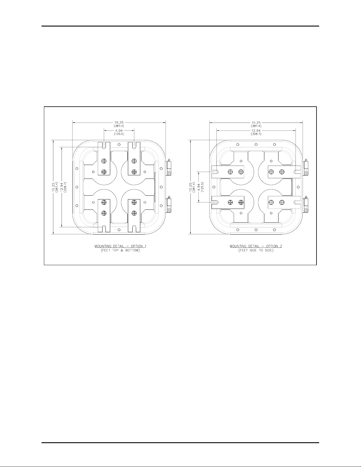
The enclosure comes s tandard with mounting feet c apable of being rota ted 90º . This allows f or top and
bottom mounting feet or side-to-side mounting f eet . The enclosure ships wit h the mounting feet in the topto-bottom configu ration, for ease of insta llation. Refer to Figu re 4 for both sets of dimensions .
Figure 4. Model 7085-005-UL/EX Enclosure Mounting Details
The en clos ure must be s ecurely fastened with 1/2-inch d i ameter s teel moun ting bolt s loc ated o n all four
mounting feet. St ainless steel hardware is r ecommended in outdoor ap plications.
N
OTE: Refer to the K illark Insta llation, Operation, and M aintenanc e D ata Sheet enclosed with t he u nit for
additi onal information.
\\s_eng\gtc proddoc s \ s t andard iom s - current release\42004 inst r. m anuals \ 42004-697l2b. doc
11/07
Page 6

Pub. 42004-697L2B
Model 7085-005-UL/ E X SmartSeri es Multi-Par ty Haz. Area Amp. Encl osure wit h RTU Page
6 of 15
Cable Entries
Refer to Figu re 5 for the UL conduit entries, and to F i gure 6 f or the EX c able gla nd ent ries. Ensure any
unus ed op enings are s ealed with proper f i ttings per local standards.
Figure 5. Model 7085-005-UL Conduit Entries
Figure 6. Model 7085-005-EX Cable Gland Entries
\\s_eng\gtc proddoc s \ s t andard iom s - current release\42004 inst r. m anuals \ 42004-697l2b. doc
11/07
Page 7

Pub. 42004-697L2B
Model 7085-005-UL/ E X SmartSeri es Multi-Par ty Haz. Area Amp. Encl osure wit h RTU Page
7 of 15
Wiring
Attach the conduit or c able gla nds to the enclosur e. Feed the wir ing throu gh these and b ring it int o the
enclosure. Attach the wires to the ter mina l blocks located behind t he amplifier b ridging plate. Follow the
wire color s carefully b ecause the colors c orres pond to GAI- Tr onic s cab l e. The wir es must be s pade-lu gged
and connect ed carefully and complet ely to the ter mina l block. An improper termination may res ult in
diminished station performance. S ee F igure 7.
CAUTION
For safe operation, connect terminal 3 of TB1 to system ground.
Local Muting
Figure 7 illus trates local speaker muti ng when stat ions are completely assembled and paging operation
occurs. N ormally, when t he s tation but ton is pressed, the paging spea ker connected t o that sta tion is
silenced (muted) to pr event acoustic feedback to the handset microphone. H owever, while the handset is in
use for party line conversations, the paging speaker is “live” t o enable pa ging c alls from other s tat ions.
To d i sa ble th e mute f eatur e, fol l o w thes e i n struction s:
1. Locate the lugged violet wire attached to terminal point 7 (mute) on the terminal block within the
enclosure.
2. Transf er the lugged violet wire to terminal point 8 (Page L1).
After any muting changes a re made, u npack the sta tion amplif ier and ins tall.
Mutual Muting
In the event that f eedback occu rs within an a rea and repositioning of the system speaker s does not help,
mutual muting may be used to correct this problem.
The following steps mut u ally mutes adjacent amplifiers/ha ndsets within a zone.
1. Ensure that the p u rple lugged wire is connect ed t o terminal 7 of TB 1 .
2. Connect terminal TB1- 7 of the ha ndset stat ion to TB1 -7 of t he s tat ion within the zone that is c ausing
feedback. This is done by u sing the sp are s ystem wire (orange conduc tor) f rom within the s ystem
ca ble t h at ru n s between th e stat i o n s.
\\s_eng\gtc proddoc s \ s t andard iom s - current release\42004 inst r. m anuals \ 42004-697l2b. doc
11/07
Page 8

Pub. 42004-697L2B
Model 7085-005-UL/ E X SmartSeri es Multi-Par ty Haz. Area Amp. Encl osure wit h RTU Page
Application
8 of 15
The Smart Series Sta tion RTU is designed for use wit h the SmartSeries amplif iers a nd handsets in a
standard multi-p arty Pa ge/ Party
®
syst em. I t is a lso possible to control an exter nal device by a c tivat ing and
deacti vating a single relay circ u i t located in the SmartS eries st ation enclos ure. This ci rcuit is r eferred to as
a r elay output. Terminal bloc k TB3, located on the rear panel of the s tat ion enclosur e, pr ovides an
interface with this relay.
In addit i on to the relay outp ut capability, the RT U also provides two inp uts. Thes e circuits provide an
interface to dry contact switches, (e.g., a pull box) that are monitored within the SmartSeries station. The
SmartS eries st ation reports any switch a c tivation to the M ast er Control Unit ( MCU).
The relay output is factory-set to be supervised through input #1. Refer to the chart on page 9. However,
you may elect to use inp u t 1 by disconnecting s upervis ion for t he relay out put.
Figure 7.
\\s_eng\gtc proddoc s \ s t andard iom s - current release\42004 inst r. m anuals \ 42004-697l2b. doc
11/07
Page 9

Pub. 42004-697L2B
Model 7085-005-UL/ E X SmartSeri es Multi-Par ty Haz. Area Amp. Encl osure wit h RTU Page
9 of 15
RTU PCBA Configur ation
The Smart Series RTU allows three choices of op erational conf igu rations. Select the conf iguration that b es t
suit s your need for circ uits. The following tab le lis ts t he R TU configu rations:
Configuration Inputs Outputs
1
2
3
Configuration 1
1 supervised input 1 supervised relay output (factory setting)
2 supervised inputs No relay output
2 su p ervised inputs 1 non-super vised relay ou tput
In the first c onf igura tion, t he relay output is sup ervised to continually ens ure the int egrity of the external
circuit. The first input, IN 1, is used to support supervision of the relay output circuit. This wiring method
requires the use of a 2 0 k-ohm, 2- watt resis tor p laced in para llel to the relay outp ut device (e. g. a b eacon or
strobe) as shown in Figure 8.
Figure 8. B eacon or Strobe
Wire t he t erminating resistor as close as p ossible to the bea c on. Su pervision is perf ormed during nonact i vation of the relay outpu t using I N 1. The second input, I N 2, remains a vailab le f or detecting switch
activations. The following section describes switch wiring choices. The RTU provides 120 V ac for
beacon power on pins TB3-28, TB3-29, and TB3-30.
OTE: This configu ration is ha rdwired at the factory.
N
\\s_eng\gtc proddoc s \ s t andard iom s - current release\42004 inst r. m anuals \ 42004-697l2b. doc
11/07
Page 10

Pub. 42004-697L2B
Model 7085-005-UL/ E X SmartSeri es Multi-Par ty Haz. Area Amp. Encl osure wit h RTU Page
Configuration 2
The second c onf iguration uses two supervised input
circ uits and does not make use of t he s i ngle relay
outp ut. This conf iguration is accomplished b y
interfacing to terminal block TB3-23 and TB3-24 for IN
1 and TB3-25 and TB3-26 for IN 2.
The ext ernal dry contact s witch, eit her norma lly open or
normally cl osed respectively, shou ld be in parallel to a
15 k-ohm resistor as shown in F igure 9.
A 5.1 k-ohm resistor should be in series to the 15
K-ohm resi stor . This pr ovides a voltage divider networ k
used to detect a short or open across the external
circuit’s ca b ling.
This c onf iguration r equ ires that t he orange wir e from
TB3 - 23 going to the relay output circuit be disconnect ed
so as no t to i n ter fere wi th supervised opera tion.
Another method of performing sup ervision using
multiple swit c hes is shown in Figure 10 . This method
requires only one 20 k- ohm resist or that is placed in
Normally Open and Normally Closed - Example
Figure 9. PLC or Switch Box
parallel to multiple norma lly open dry contact switches
at the end of line (EOL ) .
10 of 15
Figure 10. I nput L ine S upervis ion Multip le S witch - Example
\\s_eng\gtc proddoc s \ s t andard iom s - current release\42004 inst r. m anuals \ 42004-697l2b. doc
11/07
Page 11

Pub. 42004-697L2B
Model 7085-005-UL/ E X SmartSeri es Multi-Par ty Haz. Area Amp. Encl osure wit h RTU Page
Configuration 3
11 of 15
In the third configuration, t he relay output c i rcuit is nonsupervised. This means the RTU can command a system
device to ac tivat e or deactivat e without the integrity of
the external circuit being verified. In this c onf iguration,
both inputs are available.
N
OTE: Unused inputs must be terminated at terminal
block TB3 wit h a 20 k-ohm, 2-watt resi stor . Res istors
are supplied with the units. See Figure 11.
Figure 11. Unused Input
Software Configuration
The sof tware configuration of the RTU is accomplis hed through the use of the System Sta rt- u p Tool
(SST) . The t ype of RTU is dependent on the hardware configurat ion. Befor e s etting up the sof tware, it is
important t o know how t he inp uts and outputs will be used.
Interface
Use the ribbon c onnec tor s upplied wit h the unit to c onnect the Sma rtSeries relay circuit to the connector at
the ba se of the S ma rtSeries s tation. Wiring to t he RTU is performed by connecting the external circuit s to
the ap prop riate lugs on t he TB3 t erminal bloc k loc ated on t he rear panel on the enclos ure. The following
ta ble shows the wiring for T B3:
Terminal Block
Lug No.
Label
TB3-23 IN 1
TB3-24 Common
TB3-25 IN 2
TB3-26 Common
TB3-27 Spare
TB3-28 Line (hot) 120 V ac 50/60 Hz, 2.5 amps max.
TB3-29 Neutral 120 V ac 50/60 Hz
TB3-30 Earth ground
The SmartSeries RTU is pre-wired from the factory to support one supervised input and one supervised
relay output. To disable the s upervis ion of the relay outp ut circuit by IN 1, disc onnect the or ange wire
going to the relay circuit c ard loc ated a t TB3-23. T his is the only wiring modification necessary for any of
the three RT U c onf igurations.
Operation
The supervised input and relay output functions are supported by the ADVANCE system. Refer to
GAI-Tronics Pub. 42004-699L2 for Model 709-901 Handset/Speaker Amplifier for detailed operational
instructions.
\\s_eng\gtc proddoc s \ s t andard iom s - current release\42004 inst r. m anuals \ 42004-697l2b. doc
11/07
Page 12

Pub. 42004-697L2B
Model 7085-005-UL/ E X SmartSeri es Multi-Par ty Haz. Area Amp. Encl osure wit h RTU Page
12 of 15
Maintenance
Regula r insp ection and a good pr eventive maintenance program will increase the relia bility of you r
GAI-Tronics station. The GAI-Tronic s Field Service Depa rtment can formulate a service cont rac t suited
to your fac ility’s s p ecific need for preventive maintena nc e.
®
In addition, t he following procedu re can be used to keep Page/ Party
systems o perat i n g effectively .
WARNING
Before performing any of the following preventive maintenance steps, remove
all power from the station.
CAUTION
To reduce the risk of ignition of hazardous atmospheres, disconnect the equipment from the supply
circuit before making any adjustments to the amplifier's handset level.
1. Remove the a mplifier f rom the enclo sure.
2. Visually check the int erior of the enclosure for signs of c ontamination suc h as du st, c ondens ation or
process liquid.
3. Using the No. 10440-002 Maintenance Cable, plug the amplifier into the connector in the enclosur e.
Check, and if necessary, adju st the amplifier t o ma x i mize performa nc e.
4. Reinstall the amplif ier in the enclosure. Ensure t hat a ll gaskets and hardwar e are in place. F ailur e t o
install the gaskets, which als o act as s pacer s, can result in da ma ge to the connectors on t he amplifiers
and insi de t he enclosur es and ca n c aus e s ystem faults .
Inspect and c lean the machined flange fla me joint sur f aces of both the cover and b ox. Surfaces must be
smooth, f ree of nicks, scrat c hes , dirt or any foreign p article build-up that wou ld prevent a pr oper seal.
Surfa c es must seat fully aga inst ea c h other to provide a prop er explos ion- proof joint. C l ean surfaces by
wiping with a clean lint-free cloth.
Apply a light coat of Killa rk “LUBG” lub rica nt to flange surfac es and close t he cover. Ins tall and tight en
all cover bolts to 30 f t-lbs . Ma ke c erta in no c over bolts are omitted. Us e only those bolts supplied with t he
enclosure.
It may become necessary to re-terminate some or all of the enclosures in a system. If so, strip the wires
bac k to clean c opper and connect only one wire to eac h c onnector to allow for eas i er fut ure
troubleshooting.
OTE: Refer to the K illark Insta llation, Operation, and M aintenanc e D ata Sheet enclosed with t he u nit for
N
additi onal information.
Fuse
WARNING
Do not remove fuse when energized. Replace with the same type and size fuse.
RTU fuse = T2.5A, 250V, 5×20mm, IEC60127-2
\\s_eng\gtc proddoc s \ s t andard iom s - current release\42004 inst r. m anuals \ 42004-697l2b. doc
11/07
Page 13

Pub. 42004-697L2B
Model 7085-005-UL/ E X SmartSeri es Multi-Par ty Haz. Area Amp. Encl osure wit h RTU Page
Troubleshooti ng
The following t able lists some hints to aid technicians in trou bleshooting.
Problem Solution
13 of 15
Station responds to polling
messages but the relay output
does not respond.
Check for trouble report from station if the output is being supervised.
The r eport will indicate what type of trouble has oc c urred. If the
message, “Supervised Output Circuit” is reported, check relay circuit
and supervis ion pat h.
Station does not respond to poll
message.
The following device fault
message received at the MCU:
“Supervised Input Circuit”
Check a nd repla c e f u se on the back pa nel of the enclosure as well as
fuses on the SmartSeries device.
Check that the input circuit is properly terminated.
Check t he external cir c uit connected to either input of the RTU f or a
short or op en. The input circuit number is identified on the device fault
message.
Device fau l t message is not
received but the input circuits
Verify that the SST configuration is set up to report the alarm.
Remove and rep lace the S ma rtSeries H andset or Amplifier.
do not a c tivate an a larm.
A device fau lt is not repor ted to
Check and repla c e the Smar tSer ies sta tion rela y c ircuit card.
the MCU but the output circuit
does not respond t o an
activat i on c ommand.
Relay output does not engage. E nsur e the ribbon cable from the J3 connect or to the RT U board is
attached correctly.
Feedba c k occurs during page
only.
1. If a speaker is close t o the station, try u sing the muting f eature in
amplifier enclosure at terminal blocks by c onnecting the violet wire
at terminal 8 to terminal 7. See wiring diagram and refer to the
mutual muting s ection of this manual.
2. Check line ter mina tions.
3. Check location a nd orienta tion of sp eakers in the ar ea. F eedback
may be caused feedback by adjacent stations.
4. Call G AI - Tronic s service for details .
Cr oss talk occurs. One or more system cable pairs may be improp erly termina ted.
Visually inspect the system cable for accidental crossing of cable pairs
or grounds.
\\s_eng\gtc proddoc s \ s t andard iom s - current release\42004 inst r. m anuals \ 42004-697l2b. doc
11/07
Page 14

Pub. 42004-697L2B
Model 7085-005-UL/ E X SmartSeri es Multi-Par ty Haz. Area Amp. Encl osure wit h RTU Page
14 of 15
Specifications
Construction/finish................................................................................. Cast aluminum/gray polyurethane
Mounting............................................................... Wall or column, four 1/2-inch mounting feet with slots
Connections ...............................................................................Internal screw-type barrier terminal blocks
Dimensions........................................ 15.25 H × 15.25 W × 12.375 D inches (387.4 × 387.4 × 314.3 mm)
Temper atu re range (oper ating and st orage)
Model 7085-005-UL...................................................................... (-4º F to +151º F) -20º C to +66º C
Model 7085-005-EX....................................................................... (-4º F to +140º F) -20º C to +60º C
Shipping weight............................................................................................................. 75 lbs. (34.02 kg)
Enclosure............................................................................................................................ IP66/Type 4X
Approvals
Model 7085-005-UL
NRTL listed........................................................ Hazardous locations Class I, Div. 1, Groups B, C, D;
(USA and Canada) Class II, Div. 1, Groups F, G;
Class III, Div. 1
T6, Type 4X
Model 7085-005-EX
CE Mark...................................................... Complies with Low Voltage Directive 73/23/EEC, and the
EMC Directive 89/336/EEC amended by the Directive 93/68/EEC.
Certificate No. DEMKO 05 ATEX 0526157X
Notif ied Body I d No. 0539
UL International DEMKO A/S
Lyskear 8
DK-2730 Herlev
Denmark
ATEX Certified..........................................................................................ll 2 G Ex d [ib] IIB + H
Applicable standards.................................................... EN 50014:1997, A1+A2:1999, EN50020:2002,
EN 60079-0:2006 and EN 60079-1:2004
T6
2
\\s_eng\gtc proddoc s \ s t andard iom s - current release\42004 inst r. m anuals \ 42004-697l2b. doc
11/07
Page 15

Pub. 42004-697L2B
Model 7085-005-UL/ E X SmartSeri es Multi-Par ty Haz. Area Amp. Encl osure wit h RTU Page
Replacement Parts
Model No. Description
10108-011 UL Listed Handset Assembly with 6-foot PVC Cord (with cable gland)
10108-012 ATEX Certified Handset Assembly with 6-foot PVC Cord (with cable gland)
13205-006 Receiver, Handset 150-ohm
61504-111 Reed Switch Assembly with plug and spacer
61504-112 Push-Button Cable Assembly
12511-001 Dynamic Transmitter and cap
13204-002 Receiver Cap
61512-030 Party Line Selector Switch with plug cable assembly
51808-002 Fuse, RTU Control, 2.5 A, IEC
69267-001TR RTU Control PCBA
15 of 15
61210-016 RTU Ribbon Cable
NOTE: The replac ement equipment must b e ins talled by t rained, qua lif ied and competent personnel.
Installation must c omply with state a nd national regulations , as well as safety p ractices for this type of
equipment.
\\s_eng\gtc proddoc s \ s t andard iom s - current release\42004 inst r. m anuals \ 42004-697l2b. doc
11/07
Page 16

Warranty
Equipment. GAI-Tronics warrants for a period of one (1) year from the date of shipment, that any
GAI-Tronics equipment supplied hereunder shall be free of defects in material and workmanship, shall
comply with the then-current product specifications and product literature, and if applicable, shall be fit
for the purpose specified in the agreed-upon quotation or proposal document. If (a) Seller’s goods prove
to be defective in workmanship and/or material under normal and proper usage, or unfit for the purpose
specified and agreed upon, and (b) Buyer’s claim is made within the warranty period set forth above,
Buyer may return such goods to GAI-Tronics’ nearest depot repair facility, freight prepaid, at which time
they will be repaired or replaced, at Seller’s option, without charge to Buyer. Repair or replacement shall
be Buyer’s sole and exclusive remedy. The warranty period on any repaired or replacement equipment
shall be the greater of the ninety (90) day repair warranty or one (1) year from the date the original
equipment was shipped. In no event shall GAI-Tronics warranty obligations with respect to equipment
exceed 100% of the total cost of the equipment supplied hereunder. Buyer may also be entitled to the
manufacturer’s warranty on any third-party goods supplied by GAI-Tronics hereunder. The applicability
of any such third-party warranty will be determined by GAI-Tronics.
Services. Any services GAI-Tronics provides hereunder, whether directly or through subcontractors,
shall be performed in accordance with the standard of care with which such services are normally
provided in the industry. If the services fail to meet the applicable industry standard, GAI-Tronics will
re-perform such services at no cost to buyer to correct said deficiency to Company's satisfaction provided
any and all issues are identified prior to the demobilization of the Contractor’s personnel from the work
site. Re-performance of services shall be Buyer’s sole and exclusive remedy, and in no event shall GAITronics warranty obligations with respect to services exceed 100% of the total cost of the services
provided hereunder.
Warranty Periods. Every claim by Buyer alleging a defect in the goods and/or services provided
hereunder shall be deemed waived unless such claim is made in writing within the applicable warranty
periods as set forth above. Provided, however, that if the defect complained of is latent and not
discoverable within the above warranty periods, every claim arising on account of such latent defect shall
be deemed waived unless it is made in writing within a reasonable time after such latent defect is or
should have been discovered by Buyer.
Limitations / Exclusions. The warranties herein shall not apply to, and GAI-Tronics shall not be
responsible for, any damage to the goods or failure of the services supplied hereunder, to the extent
caused by Buyer’s neglect, failure to follow operational and maintenance procedures provided with the
equipment, or the use of technicians not specifically authorized by GAI-Tronics to maintain or service the
equipment. THE WARRANTIES AND REMEDIES CONTAINED HEREIN ARE IN LIEU OF AND
EXCLUDE ALL OTHER WARRANTIES AND REMEDIES, WHETHER EXPRESS OR IMPLIED BY
OPERATION OF LAW OR OTHERWISE, INCLUDING ANY WARRANTIES OF
MERCHANTABILITY OR FITNESS FOR A PARTICULAR PURPOSE.
Return Policy
If the equipment requires service, contact your Regional Service Center for a return authorization number
(RA#). Equipment should be shipped prepaid to GAI-Tronics with a return authorization number and a
purchase order number. If the equipment is under warranty, repairs or a replacement will be made in
accordance with the warranty policy set forth above. Please include a written explanation of all defects to
assist our technicians in their troubleshooting efforts.
Call 800-492-1212 (inside the USA) or 610-777-1374 (outside the USA) for help identifying the
Regional Service Center closest to you.
(Rev. 10/06)
 Loading...