

Page 1

Pub. 42004-687L2B
GAI-TRONICS® CORPORATION
A HUBBELL COMPANY
Model 703-007 SmartSeries RTU
Enclosure
Confidentiality Notice
This manual is provided solely as an operational, installation, and maintenance guide and contains
sensitive business and technical information that is confidential and proprietary to GAI-Tronics. GAITronics retains all intellectual property and other rights in or to the information contained herein, and
such information may only be used in connection with the operation of your GAI-Tronics product or
system. This manual may not be disclosed in any form, in whole or in part, directly or indirectly, to any
third party.
General Information
The Model 703-007 RTU (Remote Terminal Unit) Enclosure is designed to be a component in
GAI-Tronics SmartSeries system. It mates with a SmartSeries handset or speaker amplifier to form a
SmartSeries station.
®
When connected to a SmartSeries system, the station operates as a standard multi-party Page/Party
device. In addition, it supports supervised input circuits and a relay output (supervision optional). The
following configurations are possible:
• One supervised input circuit and one supervised relay output (factory setting)
• Two supervised input circuits and no relay output
• Two supervised input circuits and one non-supervised relay output
OTE: The relay output circuit is intended for use with GAI-Tronics-approved equipment. The circuit
N
may not support supervision of equipment that is not approved by GAI-Tronics.
How to Use the Assembly/Model
This section describes applications for the Model 703-007 SmartSeries RTU Enclosure, its hardware,
software configuration, interfaces and operation.
Application
The SmartSeries Station RTU is designed for use with the SmartSeries amplifiers and handsets in a
standard multi-party Page/Party
and deactivating a single relay circuit located in the SmartSeries station enclosure. This circuit is
referred to as a relay output. Terminal block TB3, located on the rear panel of the station enclosure,
provides an interface with this relay.
®
system. It is also possible to control an external device by activating
GAI-Tronics Corporation 400 E. Wyomissing Ave. Mohnton, PA 19540 USA
610-777-1374 800-492-1212 Fax: 610-796-5954
ISIT WWW.GAI-TRONICS.COM FOR PRODUCT LITERATURE AND MANUALS
V
Page 2

Pub. 42004-687L2B
Model 703-007 SmartSeries RTU Enclosure Page 2 of 12
In addition to the relay output capability, the RTU also provides two inputs. These circuits provide an
interface to dry contact switches, (e.g., a pull box) that are monitored within the SmartSeries station. The
SmartSeries station reports any switch activation to the Master Control Unit (MCU).
The relay output is factory-set to be supervised through input #1. Refer to Figure 1. However, you may
elect to use input #1 by disconnecting supervision for the relay output.
f:\standard ioms - current release\42004 instr. manuals\42004-687l2b.doc
11/10
Figure 1.
Page 3

Pub. 42004-687L2B
Model 703-007 SmartSeries RTU Enclosure Page 3 of 12
Hardware Configuration
The SmartSeries RTU allows three choices of operational configurations. Select the configuration that
best suits your need for circuits. The following table lists the RTU configurations:
Configuration Inputs Outputs
1
2
3
Configuration 1
One supervised input One supervised relay output (factory setting)
Two supervised inputs No relay output
Two supervised inputs One non-supervised relay output
In the first configuration, the relay output is supervised to continually ensure the integrity of the external
circuit. The first input, IN 1, is used to support supervision of the relay output circuit. This wiring
method requires the use of a 20 k-ohm, 2-watt resistor placed in parallel to the relay output device (e.g. a
beacon or strobe) as shown in Figure 2.
Figure 2. Beacon or Strobe
Wire the terminating resistor as close as possible to the beacon. Supervision is performed during nonactivation of the relay output using IN 1. The second input, IN 2, remains available for detecting switch
activations. The following section describes switch wiring choices. The RTU provides 120 V ac for
beacon power on pins TB3-28, TB3-29, and TB3-30.
N
OTE: This configuration is hardwired at the factory.
f:\standard ioms - current release\42004 instr. manuals\42004-687l2b.doc
11/10
Page 4

Pub. 42004-687L2B
Model 703-007 SmartSeries RTU Enclosure Page 4 of 12
Configuration 2
The second configuration uses two supervised input
circuits and does not make use of the single relay
output. This configuration is accomplished by
interfacing to terminal block TB3-23 and TB3-24 for
IN 1 and TB3-25 and TB3-26 for IN 2.
The external dry contact switch, either normally open
or normally closed respectively, should be in parallel to
a 15 k-ohm resistor as shown in Figure 3.
A 5.1 k-ohm resistor should be in series to the 15
K-ohm resistor. This provides a voltage divider
network used to detect a short or open across the
external circuit’s cabling.
This configuration requires that the orange wire from
TB3-23 going to the relay output circuit be
disconnected so as not to interfere with supervised
operation.
Another method of performing supervision using
multiple switches is shown in Figure 4. This method
requires only one 20 k-ohm resistor that is placed in
parallel to multiple normally open dry contact switches
at the end of line (EOL).
Figure 4. Input Line Supervision Multiple Switch - Example
Figure 3. PLC or Switch Box
Normally Open and Normally Closed - Example
f:\standard ioms - current release\42004 instr. manuals\42004-687l2b.doc
11/10
Page 5
Pub. 42004-687L2B
Model 703-007 SmartSeries RTU Enclosure Page 5 of 12
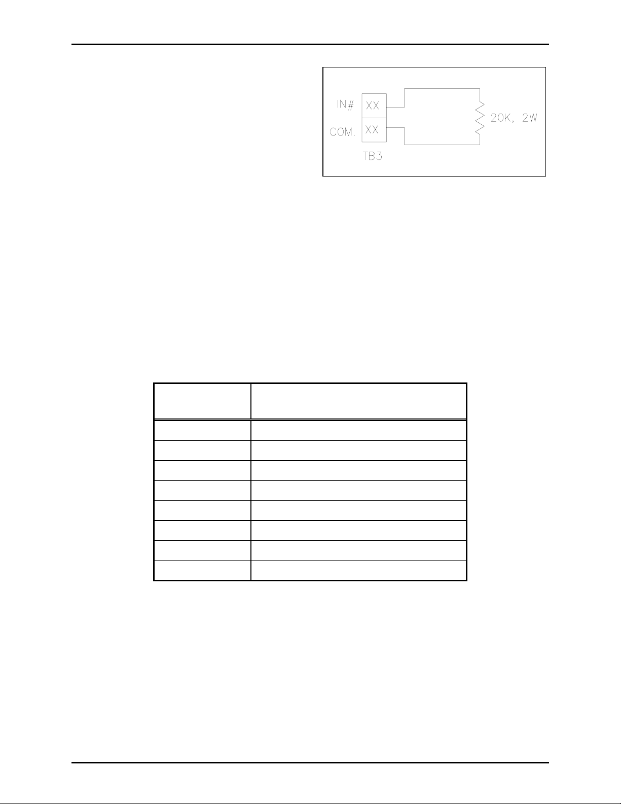
Configuration 3
In the third configuration, the relay output circuit is
non-supervised. This means the RTU can command
a system device to activate or deactivate without the
integrity of the external circuit being verified. In
this configuration, both inputs are available.
N
OTE: Unused inputs must be terminated at
terminal block TB3 with a 20 k-ohm, 2-watt resistor.
Resistors are supplied with the units. See Figure 5.
Figure 5. Unused Input
Software Configuration
The software configuration of the RTU is accomplished through the use of the System Start-up Tool
(SST). The type of RTU is dependent on the hardware configuration. Before setting up the software, it
is important to know how the inputs and outputs will be used.
Interface
Use the ribbon connector supplied with the unit to connect the SmartSeries relay circuit to the connector
at the base of the SmartSeries station. Wiring to the RTU is performed by connecting the external
circuits to the appropriate lugs on the TB3 terminal block located on the rear panel on the enclosure. The
following table shows the wiring for TB3:
Terminal Block
Lug No.
Label
TB3-23 IN 1
TB3-24 Common
TB3-25 IN 2
TB3-26 Common
TB3-27 Spare
TB3-28 Line (hot) 120 V ac 50/60 Hz, 2.5 amps max.
TB3-29 Neutral 120 V ac 50/60 Hz
TB3-30 Earth ground
The SmartSeries RTU is pre-wired from the factory to support one supervised input and one supervised
relay output. To disable the supervision of the relay output circuit by IN 1, disconnect the orange wire
going to the relay circuit card located at TB3-23. This is the only wiring modification necessary for any
of the three RTU configurations.
Operation
The supervised input and relay output functions are supported by the ADVANCE system.
f:\standard ioms - current release\42004 instr. manuals\42004-687l2b.doc
11/10
Page 6

Pub. 42004-687L2B
Model 703-007 SmartSeries RTU Enclosure Page 6 of 12
Installation
CAUTION
indicated on the approval listing in the “Specifications” section of this manual. Such installation
may cause a safety hazard and consequent injury or property damage.
WARNING
Do not disconnect equipment while energized.
Insure proper grounding to protective earthing.
When installing an add-on station, consult the appropriate system connection diagram. When used in
conjunction with the station installation information and cable layout guide, it should provide all the
information necessary to install additional Page/Party< stations.
Do not install this equipment in hazardous areas or areas other than those
Enclosure Placement
All GAI-Tronics Page/Party® units are wired in parallel. Good system layout design minimizes the cable
required for each installation. GAI-Tronics multi-conductor cable, designed especially for this
application, is recommended. The number, size, and color-coding of conductors are listed in the
appropriate system connection diagram.
System layout and power cable length are very important when installing Page/Party< equipment.
Although it varies for different systems, the general guideline is that the total power cable length should
not exceed one mile (5280 feet) for 120 V ac systems. The total cable length is the most important
consideration while cable length between the stations is generally not a factor.
Mounting
The Model 703-007 RTU Enclosure is not supplied with conduit or cable openings. Drill or punch these
openings using Figure 6 before mounting the enclosure. Whenever possible, do not enter an enclosure
from the top: side or bottom entry helps to prevent moisture from dripping onto the terminals or PCBAs.
The entry holes should be placed on the enclosure per Figure 6.
Plain entry holes must maintain the following:
• The plain hole shall be no larger than 0.7 mm above the major diameter of the entry thread.
• The gland or stopping plug is secured internally by a locknut, such that the gland or stopping plug
will be not dislodged by a 7 N-m impact.
• The enclosure will be maintained at IP 66 by a suitable sealing washer under the shoulder of the
cable gland or conduit hub.
The customer may drill plain entry holes in the enclosure providing they are in accordance with the
relevant code of practice and comply with the details shown in Figure 6. When mixed entries are
accommodated on a face they must be in the positions shown in this manual for the largest gland entry on
that face. For complex mixed entries, contact GAI-Tronics Technical Sales. Entries into the enclosure
must be via a suitable approved entry device. All unused entry holes must be fitted with a stopping plug
with a certification equal to that of the enclosure’s ATEX certification. The stopping plug shall be held
in place by a locknut.
f:\standard ioms - current release\42004 instr. manuals\42004-687l2b.doc
11/10
Page 7

Pub. 42004-687L2B
Model 703-007 SmartSeries RTU Enclosure Page 7 of 12
Figure 6. Acceptable Entry Locations
N
OTE: It is recommended that no more than two M40 glands be installed on the bottom face of the
enclosure.
f:\standard ioms - current release\42004 instr. manuals\42004-687l2b.doc
11/10
Page 8
Pub. 42004-687L2B
Model 703-007 SmartSeries RTU Enclosure Page 8 of 12
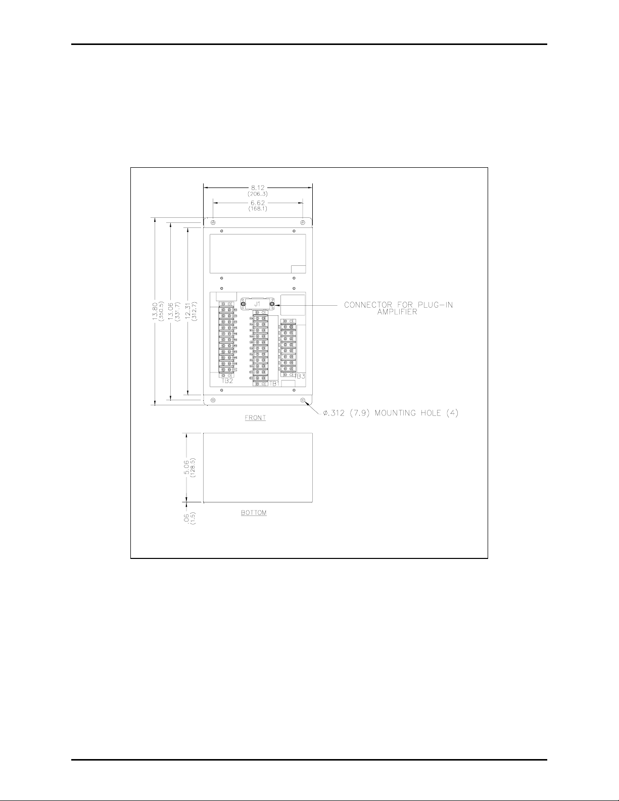
For specific mounting details, refer to Figure 7. There are four 0.312-inch diameter mounting holes in
the corners of the amplifier enclosure. The suggested mounting height for all station enclosures is 54
inches (137 cm) up to the centerline of the enclosure.
For continued IP 66 protection, torque setting for securing the amplifier to the enclosure should be 10 to
12 in-lbs. or 1.13 to 1.36 N-m.
Figure 7. Model 703-007 SmartSeries RTU Enclosure
f:\standard ioms - current release\42004 instr. manuals\42004-687l2b.doc
11/10
Page 9

Pub. 42004-687L2B
Model 703-007 SmartSeries RTU Enclosure Page 9 of 12
Wiring
Refer to the appropriate system layout diagram. Follow the wire colors carefully because the colors
correspond to GAI-Tronics multi-party cable. The wires must be spade-lugged and connected carefully
and completely to the terminal block. An improper termination may result in diminished station
performance.
CAUTION
For safe operation, connect terminal 3 of TB1 to system ground. See Figure 1.
Local Muting
The appropriate system layout diagram illustrates local speaker muting when stations are completely
assembled and paging operation occurs. Normally, when the station button is pressed, the paging speaker
connected to that station is silenced (muted) to prevent acoustic feedback to the handset microphone.
However, while the handset is in use for party line conversations, the paging speaker is “live” to enable
paging calls from other stations.
To disable the mute feature, follow these instructions:
1. Locate the lugged violet wire attached to terminal point 7 (Mute) on the terminal block within the
enclosure.
2. Transfer the lugged violet wire to terminal point 8 (Page L1).
After any muting changes are made, unpack the station amplifier and install.
Mutual Muting
In the event that feedback occurs within an area and repositioning of the system speakers does not help,
mutual muting may be used to correct this problem.
Perform the following steps to mutually mute adjacent amplifiers/handsets within a zone.
1. Ensure that the purple lugged wire is connected to terminal 7 of TB1.
2. Connect terminal TB1-7 of the handset station to TB1-7 of the station within the zone that is causing
feedback. This is done by using the spare system wire (orange conductor) from within the system
cable that runs between the stations.
f:\standard ioms - current release\42004 instr. manuals\42004-687l2b.doc
11/10
Page 10

Pub. 42004-687L2B
Model 703-007 SmartSeries RTU Enclosure Page 10 of 12
Maintenance
Regular inspection and a good preventive maintenance program will increase the reliability of your
GAI-Tronics station. The GAI-Tronics Field Service Department can formulate a service contract suited
to your facility’s specific need for preventive maintenance.
®
In addition, the following procedure can be used to keep Page/Party
systems operating effectively.
WARNING
Before performing any of the following preventive maintenance steps,
remove all power from the station.
1. Remove the amplifier from the enclosure.
2. Visually check the interior of the enclosure for signs of contamination such as dust, condensation or
process liquid.
3. Using the No. 10440-002 Maintenance Cable, plug the amplifier into the connector in the enclosure.
Check, and if necessary, adjust the amplifier to maximize performance.
4. Reinstall the amplifier in the enclosure. Ensure that all gaskets and hardware are in place. Failure to
install the gaskets, which also act as spacers, can result in damage to the connectors on the amplifiers
and inside the enclosures and can cause system faults.
It may become necessary to re-terminate some or all of the enclosures in a system. If so, strip the wires
back to clean copper and connect only one wire to each connector to allow for easier future
troubleshooting.
To maintain system operations, we recommend keeping one SmartSeries RTU per every ten installed
units in the site maintenance inventory.
If the equipment requires service, contact your Regional Service Center for a return authorization number
(RA#). Equipment should be shipped prepaid to GAI-Tronics with the return authorization number and a
purchase order number. If the equipment is under warranty, repairs will be made without charge. Please
include a written explanation of all defects to assist our technicians in their troubleshooting efforts. Call
800-492-1212 for help in identifying the Regional Service Center closest to you.
Fuse
WARNING
Do not remove fuse when energized. Replace with the same type and size fuse.
RTU fuse = T2.5A, 250V, 5×20mm, IEC60127-2
f:\standard ioms - current release\42004 instr. manuals\42004-687l2b.doc
11/10
Page 11

Pub. 42004-687L2B
Model 703-007 SmartSeries RTU Enclosure Page 11 of 12
Troubleshooting
The following table lists some hints to aid technicians in troubleshooting.
Problem Solution
Station responds to polling
messages but the relay output
does not respond.
Check for trouble report from station if the output is being supervised.
The report will indicate what type of trouble has occurred. If the
message, “Supervised Output Circuit” is reported, check relay circuit
and supervision path.
Station does not respond to poll
message.
The following device fault
message received at the MCU:
“Supervised Input Circuit”
Check and replace fuse on the back panel of the enclosure as well as
fuses on the SmartSeries device.
Check that the input circuit is properly terminated.
Check the external circuit connected to either input of the RTU for a
short or open. The input circuit number is identified on the device
fault message.
Device fault message is not
received but the input circuits
Verify that the SST configuration is set up to report the alarm.
Remove and replace the SmartSeries Handset or Amplifier.
do not activate an alarm.
A device fault is not reported to
Check and replace the SmartSeries station relay circuit card.
the MCU but the output circuit
does not respond to an
activation command.
Relay output does not engage. Ensure the ribbon cable from the J3 connector to the RTU board is
attached correctly.
Feedback occurs during page
only.
1. If a speaker is close to the station, try using the muting feature in
amplifier enclosure at terminal blocks by connecting the violet
wire at terminal 8 to terminal 7. See wiring diagram and refer to
the mutual muting section of this manual.
2. Check line terminations.
3. Check location and orientation of speakers in the area. Feedback
may be caused feedback by adjacent stations.
4. Call GAI-Tronics service for details.
Cross talk occurs. One or more system cable pairs may be improperly terminated.
Visually inspect the system cable for accidental crossing of cable
pairs or grounds.
f:\standard ioms - current release\42004 instr. manuals\42004-687l2b.doc
11/10
Page 12

Pub. 42004-687L2B
Model 703-007 SmartSeries RTU Enclosure Page 12 of 12
Specifications
Construction/finish ................................................. 16-gauge cold-rolled steel; textured gray polyurethane
Mounting............................................................................ Wall or column, four 5/16-inch mounting holes
Connections ............................................................................... Internal screw-type barrier terminal blocks
External controls........................................................................................................ Rotary selector switch
Dimensions .............................................................. 13.8 H × 8.1 W × 5.1 D inches (350 × 206 × 129 mm)
Temperature range (operating and storage)........................................ −22º F to +158º F (−30º C to +70º C)
Shipping weight .................................................................................................................... 7.5 lbs. (3.4 kg)
Approvals
Model 703-007.............................................................................................................. II 3G EEx nA IIC T6
Temperature: −30º C to 70º C
Location Zone 2
IP 66 when installed with a Model 701-305, 751-005, 701-905, or 751-905 Amplifier
NRTL listed .............................Suitable for use in hazardous locations Class I, Div. 2, Groups A, B, C, D;
Class II, Div. 2, Groups F, G;
Class III, Div. 2
when used with listed 701-305, 701-905, 751-005 or 751-905 Amplifier
Enclosure environmental rating: Type 13
CE Mark
Certificate No. DEMKO 04 ATEX 0424225X
Notified Body Id No. 0539
UL International DEMKO A/S
Lyskear 8
DK-2730 Herlev
Denmark
Replacement Parts
Contact GAI-Tronics for replacement part information.
f:\standard ioms - current release\42004 instr. manuals\42004-687l2b.doc
11/10
Page 13

Warranty
Equipment. GAI-Tronics warrants for a period of one (1) year from the date of shipment, that any
GAI-Tronics equipment supplied hereunder shall be free of defects in material and workmanship, shall
comply with the then-current product specifications and product literature, and if applicable, shall be fit
for the purpose specified in the agreed-upon quotation or proposal document. If (a) Seller’s goods prove
to be defective in workmanship and/or material under normal and proper usage, or unfit for the purpose
specified and agreed upon, and (b) Buyer’s claim is made within the warranty period set forth above,
Buyer may return such goods to GAI-Tronics’ nearest depot repair facility, freight prepaid, at which time
they will be repaired or replaced, at Seller’s option, without charge to Buyer. Repair or replacement shall
be Buyer’s sole and exclusive remedy. The warranty period on any repaired or replacement equipment
shall be the greater of the ninety (90) day repair warranty or one (1) year from the date the original
equipment was shipped. In no event shall GAI-Tronics warranty obligations with respect to equipment
exceed 100% of the total cost of the equipment supplied hereunder. Buyer may also be entitled to the
manufacturer’s warranty on any third-party goods supplied by GAI-Tronics hereunder. The applicability
of any such third-party warranty will be determined by GAI-Tronics.
Services. Any services GAI-Tronics provides hereunder, whether directly or through subcontractors,
shall be performed in accordance with the standard of care with which such services are normally
provided in the industry. If the services fail to meet the applicable industry standard, GAI-Tronics will
re-perform such services at no cost to buyer to correct said deficiency to Company's satisfaction provided
any and all issues are identified prior to the demobilization of the Contractor’s personnel from the work
site. Re-performance of services shall be Buyer’s sole and exclusive remedy, and in no event shall GAITronics warranty obligations with respect to services exceed 100% of the total cost of the services
provided hereunder.
Warranty Periods. Every claim by Buyer alleging a defect in the goods and/or services provided
hereunder shall be deemed waived unless such claim is made in writing within the applicable warranty
periods as set forth above. Provided, however, that if the defect complained of is latent and not
discoverable within the above warranty periods, every claim arising on account of such latent defect shall
be deemed waived unless it is made in writing within a reasonable time after such latent defect is or
should have been discovered by Buyer.
Limitations / Exclusions. The warranties herein shall not apply to, and GAI-Tronics shall not be
responsible for, any damage to the goods or failure of the services supplied hereunder, to the extent
caused by Buyer’s neglect, failure to follow operational and maintenance procedures provided with the
equipment, or the use of technicians not specifically authorized by GAI-Tronics to maintain or service the
equipment. THE WARRANTIES AND REMEDIES CONTAINED HEREIN ARE IN LIEU OF AND
EXCLUDE ALL OTHER WARRANTIES AND REMEDIES, WHETHER EXPRESS OR IMPLIED BY
OPERATION OF LAW OR OTHERWISE, INCLUDING ANY WARRANTIES OF
MERCHANTABILITY OR FITNESS FOR A PARTICULAR PURPOSE.
Return Policy
If the equipment requires service, contact your Regional Service Center for a return authorization number
(RA#). Equipment should be shipped prepaid to GAI-Tronics with a return authorization number and a
purchase order number. If the equipment is under warranty, repairs or a replacement will be made in
accordance with the warranty policy set forth above. Please include a written explanation of all defects to
assist our technicians in their troubleshooting efforts.
Call 800-492-1212 (inside the USA) or 610-777-1374 (outside the USA) for help identifying the
Regional Service Center closest to you.
(Rev. 10/06)
 Loading...