

Page 1

Pub.: 42004-685L2D
GAI-TRONICS® CORPORATION
A HUBBELL COMPANY
701-905 SmartSeries®
Handset/Speaker Amplifier
T ABLE OF C ONTENTS
Confidentiality Notice .....................................................................................................................1
General Information .......................................................................................................................1
Product Overview ................................................................................................................................... 1
System Requirements and Limitations ................................................................................................. 1
Features and Functions .......................................................................................................................... 1
Description of Major Components ........................................................................................................ 2
External Components ............................................................................................................................................ 2
Internal Components ............................................................................................................................................. 3
Block Diagram ......................................................................................................................................... 4
Interfaces ................................................................................................................................................. 5
Installation ......................................................................................................................................5
Operation .........................................................................................................................................6
Handset Operation .................................................................................................................................. 6
Page Announcement ............................................................................................................................................. 6
Party-Line Conversation ....................................................................................................................................... 6
Optional Features .................................................................................................................................... 7
Maintenance ....................................................................................................................................7
Fuses ......................................................................................................................................................... 7
Adjustments ............................................................................................................................................. 8
Minimum Speaker Amplifier Output Level Setting .............................................................................................. 8
Offset Level Adjustment ....................................................................................................................................... 8
VLC Level Adjustment ......................................................................................................................................... 9
Internal Adjustments ............................................................................................................................ 10
Sidetone Volume and Handset Receiver Volume ............................................................................................... 10
Troubleshooting .................................................................................................................................... 11
How to Diagnose Assembly Faults ....................................................................................................... 12
Specifications ................................................................................................................................14
Approvals ............................................................................................................................................................ 15
Replacement Parts ................................................................................................................................ 15
GAI-Tronics Corporation 400 E. Wyomissing Ave. Mohnton, PA 19540 USA
610-777-1374 800-492-1212 Fax: 610-796-5954
V
ISIT WWW.GAI-TRONICS.COM FOR PRODUCT LITERATURE AND MANUALS
Page 2

PUB. 42004-685L2D
GAI-TRONICS® CORPORATION
A HUBBELL COMPANY
701-905 SmartSeries®
Handset/Speaker Amplifier
Confidential ity Notice
This manual is provided solely as an operational, installation, and maintenance guide and contains
sensitive business and technical information that is confidential and proprietary to GAI-Tronics.
GAI-Tronics retains all intellectual property and other rights in or to the information contained herein,
and such information may only be used in connection with the operation of your GAI-Tronics product or
system. This manual may not be disclosed in any form, in whole or in part, directly or indirectly, to any
third party.
General Information
Product Overview
This document discusses installing, operating, and maintaining the SmartSeries® 701-905
Handset/Speaker Amplifier. It provides the following features:
Supports one-way page announcements over system speakers
Serves as an amplifier to broadcast page announcements over the station’s speaker
Supports party-line (two-way) communication with other system users
Serves as a control interface to optional devices such as the party line End-of-Line Module or the
SmartSeries
®
station Remote Terminal Unit when installed into a SmartSeries® RTU enclosure.
System Requirements and Limitations
The SmartSeries® 701-905 Handset/Speaker Amplifier is designed to provide an intelligent handset for
use on the GAI-Tronics multi-party system cable (system cable) in either a standard Page/Party
or an ADVANCE system.
®
system
Features and Functions
Page and party from the integral handset or an
auxiliary headset connected to the front panel, if
equipped.
Monitor and control the handset and auxiliary
connections, if equipped.
Measure the ambient noise and adjust the speaker
output level accordingly.
Support an optional SmartSeries
Remote Terminal Unit, which monitors and
supervises input and output devices.
Support an optional party line End-of-Line
Module, which supervises party line 1.
Transfer data messages and audio on the
system cable.
®
station
Supervise the local speaker.
GAI-Tronics Corporation 400 E. Wyomissing Ave. Mohnton, PA 19540 USA
610-777-1374 800-492-1212 Fax: 610-796-5954
V
ISIT WWW.GAI-TRONICS.COM FOR PRODUCT LITERATURE AND MANUALS
Page 3
Pub. 42004-685L2D
701-905
SMARTSERIES® HANDSET/SPEAKER AMPLIFIER PAGE 2 of 15
Description of Major Components
These assemblies include external components accessible to the user as well as internal components or
subassemblies.
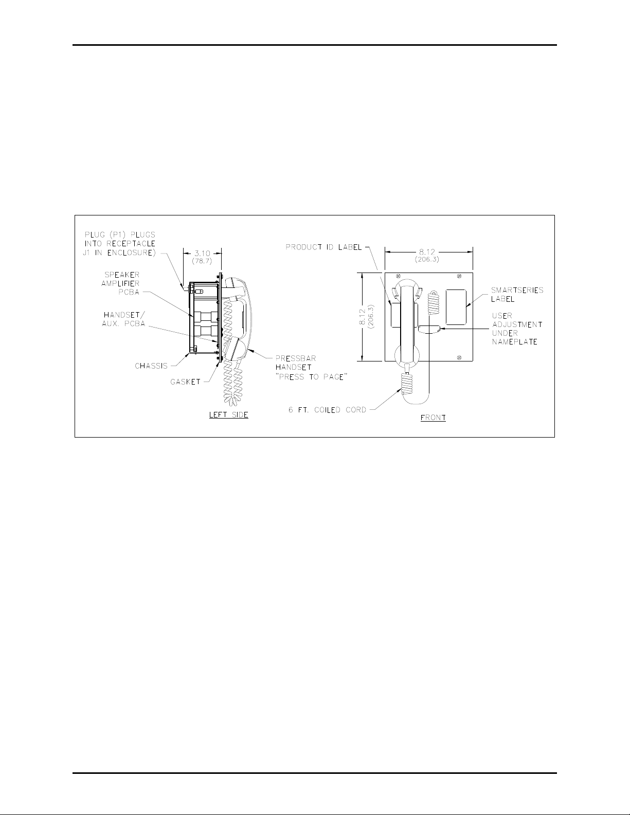
External Components
As shown from the front in Figure 1, the assembly includes a handset and cradle. When the handset is
lifted from the cradle or replaced in the cradle, a hookswitch (a magnetic reed switch) in the cradle signals
the appropriate status to the microcontroller within the assembly. To the right of the cradle the GAITronics nameplate concealing the User Level Adjustment control.
Figure 1. Front View
f:\standard ioms - current release\42004 instr. man uals\42004-685l2d.doc
03/12
Page 4
Pub. 42004-685L2D
701-905
Internal Components
SMARTSERIES® HANDSET/SPEAKER AMPLIFIER PAGE 3 of 15
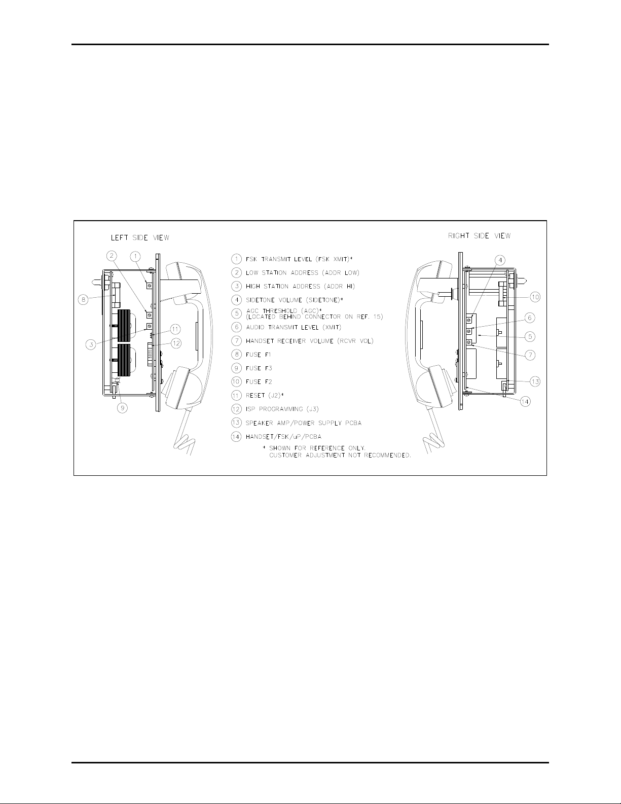
As shown from the side in Figure 2, the assembly contains the following components or subassemblies:
Chassis
Front panel affixed to the front of the chassis
Handset Amp/FSK/P PCBA (printed circuit board assembly) (Ref. 14) affixed to the rear of the
front panel
Speaker Amp/Power Supply PCBA (Ref. 13) affixed to the rear of the chassis, with a plug (P1) at the
top, pointing to the rear
Figure 2. Side View
f:\standard ioms - current release\42004 instr. man uals\42004-685l2d.doc
03/12
Page 5
701-905
SMARTSERIES® HANDSET/SPEAKER AMPLIFIER PAGE 4 of 15
Block Diagram
Pub. 42004-685L2D
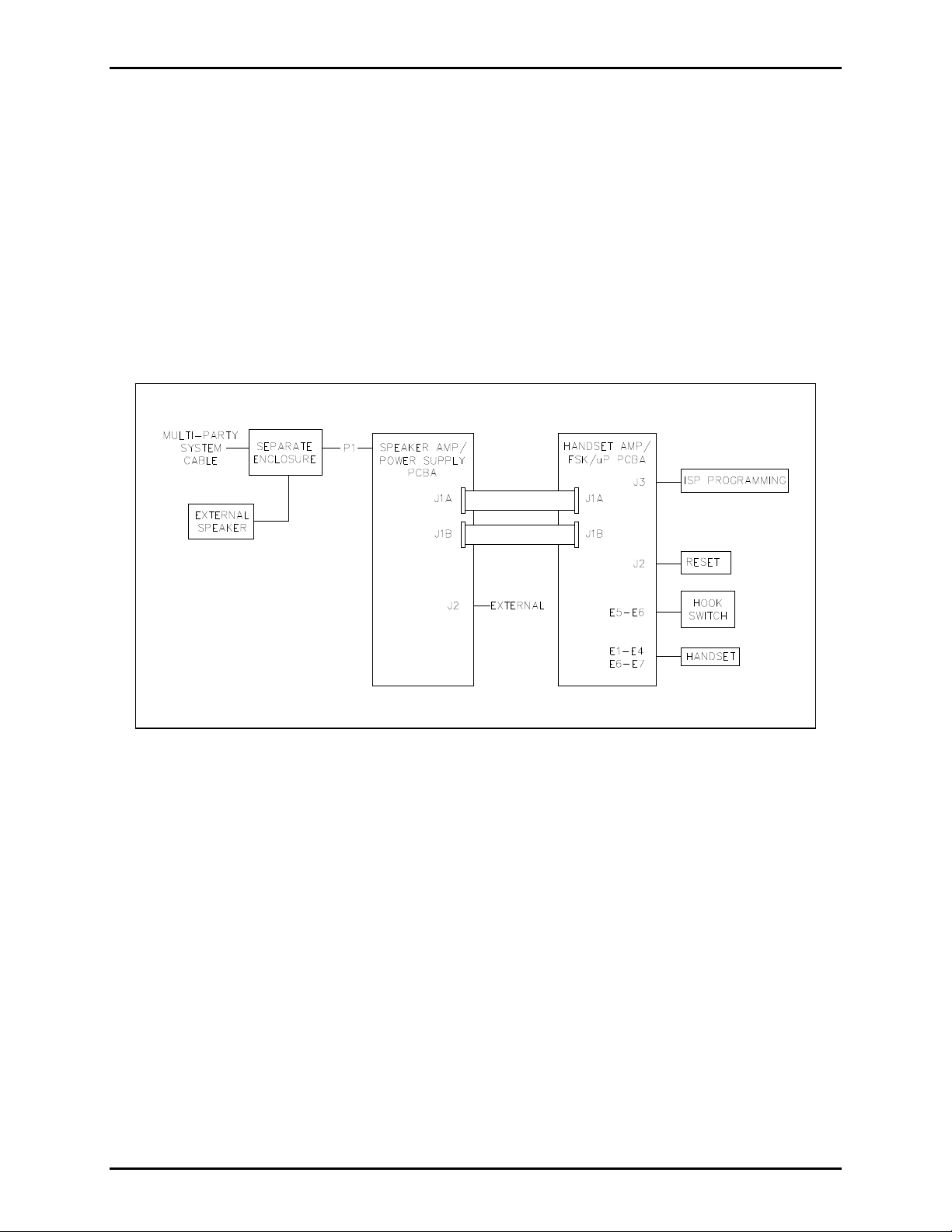
The P1 connector on the back of the Speaker Amp/Power Supply PCBA plugs into a socket in an
enclosure connected to the system cable, accessing the Page/Party
®
lines and ac power. The Speaker
Amp/Power Supply PCBA contains the low voltage power supplies and the speaker amplifier circuitry.
Connector J1A and J1B on the Speaker Amp/Power Supply connects regulated +5 V dc, +/−15 V dc, and
V
voltages along with control, monitoring, and line signals to the J1A and J1B on the Handset
RLY
Amp/FSK/P PCBA. Connector J2 of the Speaker Amp/Power Supply PCBA connects to optional
external devices.
The Handset Amp/FSK/P PCBA has connections to the handset and the hookswitch via spade terminal
connectors E1 to E7, and it has connections to the optional front panel auxiliary connector, via J4.
Figure 3. Block Diagram
f:\standard ioms - current release\42004 instr. man uals\42004-685l2d.doc
03/12
Page 6

Pub. 42004-685L2D
701-905
SMARTSERIES® HANDSET/SPEAKER AMPLIFIER PAGE 5 of 15
Interfaces
The assembly interfaces to the system cable, an external loud speaker, and auxiliary devices via P1, a 16pin connector. All connections to the system cable are made by qualified installation technicians during
the system installation.
Direct questions about these connections to the GAI-Tronics Field Service Department at 800-492-1212
inside the USA or 610-777-1374 outside the USA. Other connections on the Speaker Amp/Power Supply
PCBA provide quick connect/disconnect of subassemblies.
Connector J2 on the bottom of the Speaker Amp/Power Supply PCBA connects to optional devices such
as the SmartSeries Remote Terminal Unit (RTU) installed in specially designed enclosures.
Installation
CAUTION
Do not install this equipment in hazardous areas other than those indicated
on the approval listing in the “Specifications” section of this manual. Such installation may cause a
safety hazard and consequent injury or property damage.
WARNING
Do not disconnect equipment while energized.
The SmartSeries
GAI-Tronics Page/Party
®
Model 701-905 Handset/Speaker Amplifier assembly plugs directly into any standard
®
Series enclosures. Use extra care not to damage the protruding latch wings of
connector J2 located on the bottom edge of the amplifier during installation.
®
They also plug into standard SmartSeries
enclosures such as a SmartSeries® station RTU enclosure, an
Emergency Party Line (EPL) enclosure, or an enclosure that houses a party line End-of-Line (EOL)
Module. When installing the assembly in one of these enclosures, you must also connect the
10-conductor keyed ribbon cable to J2 on the bottom of the Speaker Amp/Power Supply PCBA. Be sure
that the red line on the edge of the cable lines up with J2-pin 1.
Ensure that the connectors mate securely and then tighten the four screws in the corners of the front panel.
For continued IP 66 protection, torque setting for securing the amplifier to the enclosure should be 10 to
12 in-lbs. or 1.13 to 1.36 n-m.
f:\standard ioms - current release\42004 instr. man uals\42004-685l2d.doc
03/12
Page 7

Pub. 42004-685L2D
701-905
SMARTSERIES® HANDSET/SPEAKER AMPLIFIER PAGE 6 of 15
Operation
Note regarding the busy tone: A busy tone is heard in the receiver when either of the following occurs:
a page of a higher priority is in progress
a page is attempted within one second of a previous page
Handset Operation
The handset allows the user to make page announcements and conduct party-line conversations.
Page Announcement
To make a page announcement for a party-line conversation, perform the following steps:
1. Lift the handset from the cradle.
2. Select an available party line.
3. Press the handset pressbar.
4. Make your announcement when the wait tone stops. If the page resource is already in use, you hear a
busy tone. Release the handset pressbar, then try again.
5. Release the handset pressbar.
6. When the party answers conduct your conversation.
7. Replace the handset in the cradle at the end of the conversation.
Party-Line Conversation
To conduct a party-line conversation, perform the following steps:
1. For a multi-party enclosure select the appropriate party line.
2. Lift the handset from the cradle.
3. Conduct your conversation.
4. Replace the handset in the cradle when the conversation is finished.
f:\standard ioms - current release\42004 instr. man uals\42004-685l2d.doc
03/12
Page 8

701-905
SMARTSERIES® HANDSET/SPEAKER AMPLIFIER PAGE 7 of 15
Optional Features
Pub. 42004-685L2D
The following features are available as options to the standard configuration of a station used in an
ADVANCE system and installed in a standard SmartSeries
®
or a custom enclosure. These features can
be configured. Contact the GAI-Tronics Field Service Department at 800-492-1212 inside the USA or
610-777-1374 outside the USA for further information about these features.
The Selected Page Destination feature allows the manual selection of one of four page destinations.
The Supervised Input feature allows the monitoring and supervision of one or two initiating device
circuits (IDCs), initiating an alarm when the supervised device is activated.
The Power Relay Module provides a relay contact output, typically to switch power to a visual
signaling device, for directed or relay group operation. Supervision of the controlled device’s cable
can also be enabled.
The Station Emergency Party Line feature supports annunciation for two party lines.
Maintenance
Regular inspection and a good preventive maintenance program will increase the reliability of your
GAI-Tronics station. The GAI-Tronics Field Service Department can formulate a service contract suited
to your facility’s specific need for preventive maintenance.
If the equipment requires service, contact your Regional Service Center for a return authorization number
(RA#). Equipment should be shipped prepaid to GAI-Tronics with the return authorization number and a
purchase order number. If the equipment is under warranty, repairs will be made without charge. Please
include a written explanation of all defects to assist our technicians in their troubleshooting efforts. Call
800-492-1212 for help in identifying the Regional Service Center closest to you.
WARNING
Before performing any of the following preventive maintenance steps, remove
all power from the station.
1. Inspect and replace frayed or cracked wiring.
2. Secure/replace loose wires and spade terminals.
3. Remove corrosion from terminals.
Fuses
WARNING
Do not remove fuses when energized. Replace with the same type and size fuse.
F1 = T.160A, 250V, 520mm, IEC 60127-2.
F2 = T.630A, 250V, 520mm, IEC 60127-2.
F3 = T.125A, 250V, 520mm, IEC 60127-2.
f:\standard ioms - current release\42004 instr. man uals\42004-685l2d.doc
03/12
Page 9

Pub. 42004-685L2D
701-905
SMARTSERIES® HANDSET/SPEAKER AMPLIFIER PAGE 8 of 15
Adjustments
The User Adjustment Control is located beneath the GAI-Tronics nameplate on the front panel. Refer to
Figure 1. It is used to make all user adjustments normally required for installation. Loosen the two
screws on the GAI-Tronics nameplate and rotate it counterclockwise to access the adjustment hole. Make
adjustments by inserting a 1/8-inch flat blade screwdriver through the access hole and into the
potentiometer located directly behind the hole.
The User Adjustment Control potentiometer can be used to make three separate adjustments:
Minimum speaker amplifier output level setting
Offset amplifier level (difference between the ambient noise and the amplifier output levels)
adjustment
VLC (Volume Level Control) adjustment (sets a preset speaker level to override the normal volume
control setting)
Minimum Speaker Amplifier Output Level Setting
To set the minimum amplifier output level, insert the 1/8-inch flat blade screwdriver into the User
Adjustment Control and set it fully counterclockwise
indicating the speaker amplifier is in the Minimum Level Adjustment mode. A continuous tone should be
heard after the beep tone. (See note below).
. Listen for a single beep from the speaker
This test tone is used as a reference to adjust the speaker amplifier output level to the desired volume.
Turn the adjustment pot clockwise for the desired output. The test tone automatically shuts off 5 seconds
after the last adjustment. The factory default setting for minimum level is 4.0 watts nominal.
NOTE: If the page line is in use immediately after the beep tone, the page signal should be used to make
the minimum level adjustment. If the page line is inactive following the beep tone, a continuous tone is
activated to make the minimum level adjustment. After the tone is activated, all page line activity is
ignored until completion of the adjustment.
Offset Level Adjustment
The Offset Level allows the output of the SmartVolume™ speaker amplifier to maintain a set difference
or “offset” between the ambient noise level and the speaker output level. Turn the User Adjustment
Control fully clockwise
and listen for the two beep tones indicating that the station is in the Offset
Adjustment mode. A continuous tone should be heard from the station speaker. Turn the adjustment pot
counterclockwise to the desired output level.
OTE: If the page line is in use immediately after the two beep tones are heard, the page signal should be
N
used to make the offset level adjustment. If the page line is inactive immediately following the beep
tones, a continuous tone is activated to make the minimum level adjustment. After the tone is activated,
all page line activity is ignored until completion of the adjustment
f:\standard ioms - current release\42004 instr. man uals\42004-685l2d.doc
03/12
Page 10

Pub. 42004-685L2D
701-905
VLC Level Ad justment
SMARTSERIES® HANDSET/SPEAKER AMPLIFIER PAGE 9 of 15
When activated, the VLC overrides the normal volume control setting allowing the amplifier level to
change to a preset level during an emergency page. The factory default setting for the VLC Level is 10%
of maximum power (nominally 1.2 watts).
OTE: The system must be equipped with a SmartSeries
N
®
MCU (Master Control Unit) to activate the
VLC function.
To adjust the VLC Level:
1. Force the station into the VLC mode by having someone execute a page from a station programmed
by the MCU to activate the VLC function.
2. During the page, turn the User Adjustment Control fully counterclockwise
, and listen for two beep
tones through the page speaker indicating the VLC Adjustment mode has been activated.
3. After the two beep tones, turn the User Adjustment Control to the desired speaker level using the live
paging signal to adjust the level. The station automatically exits the VLC Adjustment mode and
reverts to normal operation 5 seconds after the last pot adjustment.
f:\standard ioms - current release\42004 instr. man uals\42004-685l2d.doc
03/12
Page 11

Pub. 42004-685L2D
701-905
SMARTSERIES® HANDSET/SPEAKER AMPLIFIER PAGE 10 of 15
Internal Adjustments
Although they typically require no adjustments, the following volume levels can be set internally:
Sidetone Volume and Handset Receiver Volume
To make an adjustment it is necessary to remove the assembly from its enclosure and make a temporary
connection between the assembly and the enclosure. Refer to Figure 2 for the reference numbers and
locations of the adjustment controls. Turn a control clockwise to increase the volume or threshold; turn it
counterclockwise to decrease the volume or threshold. Use a small flat-blade screwdriver with an
insulated shaft to make adjustments.
To access the controls, perform the following steps:
1. Loosen the four screws that secure the front panel.
2. Remove the assembly from the enclosure. If the enclosure is equipped with an optional EOL Module
or SmartSeries
®
station RTU, be careful to not disconnect the ribbon cable on J2 of the Speaker
Amp/Power Supply PCBA.
3. Connect the assembly to the enclosure using a Model 10440-002 Maintenance Cable between P1 on
the assembly and J1 on the enclosure.
4. Locate and adjust the control on the appropriate PCBA.
5. When you are finished with the adjustment:
a) Disconnect the Model 10440-002 Maintenance Cable.
b) Insert the assembly into the enclosure.
c) Tighten the four screws.
Handset Receiver Volume
Use the control labeled RCVR VOL (Ref. 7, on the Handset/FSK/P PCBA) to adjust to the desired level
the handset receiver volume for voice signals from a party line.
Sidetone Volume
The control labeled SIDETONE (Ref. 4, on the Handset/FSK/P PCBA) adjusts the handset/headset
sidetone.
f:\standard ioms - current release\42004 instr. man uals\42004-685l2d.doc
03/12
Page 12

701-905
SMARTSERIES® HANDSET/SPEAKER AMPLIFIER PAGE 11 of 15
Troubleshooting
The following table lists some hints to aid technicians in troubleshooting.
Problem Possible Solution
Pub. 42004-685L2D
Any problem with
station performance
Speaker volume needs
adjustment
Remove the assembly from the enclosure and examine it carefully for obvious
faults such as unconnected plugs, loose connections where the wires from the
handset and hookswitch connect to the Handset/FSK/P PCBA, and so on.
Determine whether the fault is in the assembly, or in the system, by plugging
in a known good spare assembly (set to the same address as the assembly
removed). If the fault is in the assembly, remove it for repair.
OTE: When replacing the assembly, perform the following steps:
N
1. Set the address on the new assembly to 0, 3.
2. Plug the assembly into the enclosure.
3. After about 10 seconds, remove the assembly. The station is now set up
to request a download of configuration variables from the MCU.
4. Set the unit to the correct address. Set the address to 0, 4 for conventional
Page/Party
®
operation or consult the ADVANCE system manual for
address assignment information.
5. Plug the assembly back into the enclosure. The station initiates a
configuration download request (ADVANCE systems only). The time
required to complete the download depends upon system configuration
and system activity, but several seconds is typical.
Use the USER ADJ control to adjust the Minimum Level, Offset Level, or
VLC Level (as appropriate). Refer to the “Adjustments” section on page 8.
Incoming handset
speech level needs
Use the RCVR VOL control to adjust the handset receiver volume. Refer to the
“Adjustments” section of this document.
adjustment
Acoustic feedback or
speech distortion
during page or party
operation
or
The user hears himself
If the problem affects all stations, the line may not be terminated
correctly, may have loose connections, or a short to ground. Line balance
connections are critical.
If the problem affects only this assembly, the problem may be with its
sidetone setting. Contact the GAI-Tronics Field Service Department.
when speaking
Feedback during page
only
Check within the enclosure for a purple wire on terminal 7: this is the
default setting for local speaker mute. If the wire is on terminal 8, then
the speaker is unmuted and may be causing feedback. Connect the wire
to terminal 7.
An adjacent speaker could be causing feedback. If an adjacent speaker is
the source of the feedback, adjust the orientation of the speaker so that it
is not aimed directly at the station. As a last resort, enable the mutual
muting function of the station. This is done by interconnecting terminal 7
of the two stations with the spare orange wire in the system cable (if this
wire is available).
Crosstalk Likely to be external to the assembly and related to system cable faults.
f:\standard ioms - current release\42004 instr. man uals\42004-685l2d.doc
03/12
Page 13

Pub. 42004-685L2D
701-905
SMARTSERIES® HANDSET/SPEAKER AMPLIFIER PAGE 12 of 15
How to Diagnose Assembly Faults
When the assembly is in an ADVANCE system that includes a vacuum fluorescent display (VFD), faults
may be automatically detected, transmitted to the MCU in data messages, and displayed or printed. Fault
messages and possible solutions for their causes are described in the table below.
Fault Message Cause and Effect Possible Solution
Watch-Dog timer
Processor has Reset
xd times
(Where x is the
decimal number of
times the watchdog
timer has reset the
processor.)
Stuck Contact on
Polled Device
Paging Pressbar
Depressed
Stuck Contact on
Polled Device
Handset Off-hook
Cause—The watchdog timer has forced the
processor to reset. This occurs when the reset
pins (J2) on the Handset/FSK/P PCBA are
temporarily shorted or when the watchdog
timer does not receive regular status pulses
from U4 on the Handset/FSK/P PCBA.
Effect—The processor maintains a count of
the number of resets. If the station is powered
down, the count restarts at zero. The station
still amplifies incoming pages. For the fourth
and subsequent resets, the count is zero.
Cause—The station has been in page mode
longer than the configured page limit.
Effect—Station page is cut off. When the
pressbar is released, a restore message is sent
to the MCU. The station then resumes normal
operation.
Cause—The station has been in the off-hook
state longer than the configured time limit.
Effect—Station handset/headset operation is
cut off. When the station is returned to the
on-hook state, a restore message is sent to the
MCU. The station then resumes normal
operation.
Verify that the reset pins
2 and 3 (J2) on the
Handset/FSK/P PCBA
are not shorted.
Replace the
Handset/FSK/P PCBA.
Verify that neither the
handset pressbar nor the
headset page switch is
stuck.
Replace the
Handset/FSK/P PCBA.
Replace the Speaker
Amp/Power Supply
PCBA.
Verify that neither the
handset is off-hook nor
the headset is connected.
Replace the
Handset/FSK/P PCBA,
or cradle.
Replace the Speaker
Amp/Power Supply
PCBA.
Supervised Audio
Path
Handset
Supervised Audio
Path
Page Amp
f:\standard ioms - current release\42004 instr. man uals\42004-685l2d.doc
03/12
Cause—The station failed its internal health
check of the Handset/FSK/P PCBA.
Effect—The station disables the handset
amplifier health-check function after the first
failure.
Cause—The station failed its internal speaker
amplifier health check.
Effect—The station disables the speaker
amplifier health-check function after the first
failure.
Replace the
Handset/FSK/P PCBA.
Replace the Speaker
Amp/Power Supply
PCBA.
Replace the Speaker
Amp/Power Supply PCBA.
Page 14

Pub. 42004-685L2D
701-905
SMARTSERIES® HANDSET/SPEAKER AMPLIFIER PAGE 13 of 15
Fault Message Cause and Effect Possible Solution
Supervised Audio
Path
Speaker Voice Coil
Cause—The station is detecting no ambient
noise at the speaker or is detecting an ambient
noise lower than the configured failure
threshold. This may occur if there is a fault in
the speaker wire or a fault at the voice coil.
This also may occur if the ambient noise at
the speaker is too low, as is the case in a quiet
room.
Effect—The station continues measuring
speaker ambient noise. When acceptable
noise levels are subsequently measured, a
restore message is sent to the MCU.
Polled device Cause—This message is output by the MCU
when it loses communication with the station.
This may occur if there is a fault in the page
line, if the station is powered-down, or if there
is some fatal malfunction within the station.
Effect—The MCU continues to attempt
communication with the station. When
communication is resumed, a restore message
is sent to the MCU.
Verify that the speaker
wire is connected and
intact.
Verify that the voice coil
is connected and intact.
Replace the Speaker
Amp/Power Supply
PCBA.
Replace Handset/FSK/P
PCBA.
Verify that the page line
is connected and intact.
Verify that the station is
installed correctly.
Replace the
Handset/FSK/P PCBA.
Polled End-of-line
device
Cause—This message is the same as the
“Polled device” fault, except that the affected
station has been defined as an end-of-line
station in the MCU configuration.
Effect—When this fault occurs, the red EOL
FLT LED on the PPI bezel lights. When
communication is resumed, the LED
extinguishes and a restore message is sent to
the MCU.
Verify that the page line
is connected and intact.
Verify that the station is
installed correctly.
Replace the station
assembly.
f:\standard ioms - current release\42004 instr. man uals\42004-685l2d.doc
03/12
Page 15

Pub. 42004-685L2D
701-905
SMARTSERIES® HANDSET/SPEAKER AMPLIFIER PAGE 14 of 15
Specification s
Electrical
Supply voltage .......................................................................... 90–140 V ac (120 V ac nominal), 50/60 Hz
Power consumed @ nominal ac ........... Zero/maximum signal (12 watts): 15 VA, 9 watts/59 VA, 32 watts
Speaker Amplifier
Output ............................................................................... 12 watts minimum, with nominal supply voltage
Frequency response .......................................................................... 350–6,500 Hz, +0/−3 dB, ref. to 1 kHz
Distortion ......................................................................................... 1% maximum THD @ 1 kHz, 12 watts
SmartVolume™
Monitor range (low gain) ...................................................................................................... 62–100 dB SPL
Offset (above ambient) user level adjustment ................................................................................... 0–48 dB
Minimum user level adjustment .................................................................................... Off; 85–125 dB SPL
Handset Amplifier
Output ................................................................................................... 1.5 V
Frequency response with 5 mV
input (AGC on) ......................... 350–6,500 Hz, +0/−3 dB ref. to 1 kHz
RMS
nominal into 33-ohm load
RMS
Distortion ..................................................................................................... 1.5% maximum THD @ 1 kHz
Mechanical
Dimensions ............................................. 8.12 H 8.12 W 6.12 D inches (206 206 155 mm), overall
Environmental
Temperature range ........................................ −22° F to +158° F (−30° C to +70° C), operating and storage
Humidity ..................................................................................................................... 95%, non-condensing
f:\standard ioms - current release\42004 instr. man uals\42004-685l2d.doc
03/12
Page 16

Pub. 42004-685L2D
701-905
Approvals
SMARTSERIES® HANDSET/SPEAKER AMPLIFIER PAGE 15 of 15
Model 701-905 Amplifier ............................................................................................. II 3G EEx nA IIC T4
Location Zone 2
IP 66 when installed in a 702-006, 703-006, 703-007,
7325-106, or 7325-107 Series enclosure
NRTL listed .............................. Suitable for use in hazardous locations Class I, Div. 2, Groups A, B, C, D;
Class II, Div. 2, Groups F, G;
Class III, Div. 2
when used with listed 702-006, 703-006, 703-007
7325-106, or 7325-107 Series enclosure
CE Mark
Temperature code ........................................................................................................................................ T4
Certificate No. DEMKO 04 ATEX 0424225X
Notified Body Id No. 0539
UL International DEMKO A/S
Lyskear 8
DK-2730 Herlev
Denmark
Replacement Parts
Contact GAI-Tronics for replacement part information.
f:\standard ioms - current release\42004 instr. man uals\42004-685l2d.doc
03/12
Page 17

Warranty
Equipment. GAI-Tronics warrants for a period of one (1) year from the date of shipment, that any
GAI-Tronics equipment supplied hereunder shall be free of defects in material and workmanship, shall
comply with the then-current product specifications and product literature, and if applicable, shall be fit
for the purpose specified in the agreed-upon quotation or proposal document. If (a) Seller’s goods prove
to be defective in workmanship and/or material under normal and proper usage, or unfit for the purpose
specified and agreed upon, and (b) Buyer’s claim is made within the warranty period set forth above,
Buyer may return such goods to GAI-Tronics’ nearest depot repair facility, freight prepaid, at which time
they will be repaired or replaced, at Seller’s option, without charge to Buyer. Repair or replacement shall
be Buyer’s sole and exclusive remedy. The warranty period on any repaired or replacement equipment
shall be the greater of the ninety (90) day repair warranty or one (1) year from the date the original
equipment was shipped. In no event shall GAI-Tronics warranty obligations with respect to equipment
exceed 100% of the total cost of the equipment supplied hereunder. Buyer may also be entitled to the
manufacturer’s warranty on any third-party goods supplied by GAI-Tronics hereunder. The applicability
of any such third-party warranty will be determined by GAI-Tronics.
Services. Any services GAI-Tronics provides hereunder, whether directly or through subcontractors,
shall be performed in accordance with the standard of care with which such services are normally
provided in the industry. If the services fail to meet the applicable industry standard, GAI-Tronics will
re-perform such services at no cost to buyer to correct said deficiency to Company's satisfaction provided
any and all issues are identified prior to the demobilization of the Contractor’s personnel from the work
site. Re-performance of services shall be Buyer’s sole and exclusive remedy, and in no event shall GAITronics warranty obligations with respect to services exceed 100% of the total cost of the services
provided hereunder.
Warranty Periods. Every claim by Buyer alleging a defect in the goods and/or services provided
hereunder shall be deemed waived unless such claim is made in writing within the applicable warranty
periods as set forth above. Provided, however, that if the defect complained of is latent and not
discoverable within the above warranty periods, every claim arising on account of such latent defect shall
be deemed waived unless it is made in writing within a reasonable time after such latent defect is or
should have been discovered by Buyer.
Limitations / Exclusions. The warranties herein shall not apply to, and GAI-Tronics shall not be
responsible for, any damage to the goods or failure of the services supplied hereunder, to the extent
caused by Buyer’s neglect, failure to follow operational and maintenance procedures provided with the
equipment, or the use of technicians not specifically authorized by GAI-Tronics to maintain or service the
equipment. THE WARRANTIES AND REMEDIES CONTAINED HEREIN ARE IN LIEU OF AND
EXCLUDE ALL OTHER WARRANTIES AND REMEDIES, WHETHER EXPRESS OR IMPLIED BY
OPERATION OF LAW OR OTHERWISE, INCLUDING ANY WARRANTIES OF
MERCHANTABILITY OR FITNESS FOR A PARTICULAR PURPOSE.
Return Policy
If the equipment requires service, contact your Regional Service Center for a return authorization number
(RA#). Equipment should be shipped prepaid to GAI-Tronics with a return authorization number and a
purchase order number. If the equipment is under warranty, repairs or a replacement will be made in
accordance with the warranty policy set forth above. Please include a written explanation of all defects to
assist our technicians in their troubleshooting efforts.
Call 800-492-1212 (inside the USA) or 610-777-1374 (outside the USA) for help identifying the
Regional Service Center closest to you.
(Rev. 10/06)
 Loading...