

Page 1

Pub. 42004-319
GAI-TRONICS® CORPORATION
A HUBBELL COMPANY
Model 701-312 Page/Part y®
600-Ohm Handset/Speaker Amplifier
Confidentiality Notice
This manual is pr ovided s olely as a n op erat ional, installation, and maintenance guide and contains sens itive
bus ines s and t echnic al infor ma tion tha t is confident i al and p roprietary to G AI-Tronics. GAI-Tronics
retains a ll intellectual pr operty and other rights in or to t he inf ormation c ontained herein, and s uch
informa tion may only be used in connection wit h the operation of you r GAI- Tronic s pr oduct or system.
This ma nual may not be disclosed in any form, in whole or in p art, dir ec tly or indirectly, to any t hird pa rty.
General Information
The Model 701-312 Page/Party® 600-Ohm Handset/Speaker Amplifier is an important component of a
GAI-Tronics Pa ge/Pa rty
cable runs. Use the Model 701-312 Handset/Speaker Amplifier in Page/Party
runs exceeding one mile (1.6 km) from the system line balanc e assembly.
®
syst em. This ha ndset/s peaker amplifier is ideal for applic ations that require long
®
systems that require cable
Installation
NOTE
Do not install the Model 701-312 in a 33-ohm system or audio levels will be low.
CAUTION
Do not install t his eq uipment in hazardous areas. Installing in hazardous areas may cause a safety
hazard and consequent injury or property damage.
The Model 701-312 Handset/Speaker Amplifier is a plug-in amplifier that mates directly with the Model
702, 703, 732 and 733 Series Amplifier Enclosures. To install the handset/speaker amplifier, simply plug
it i n to th e en clos ure.
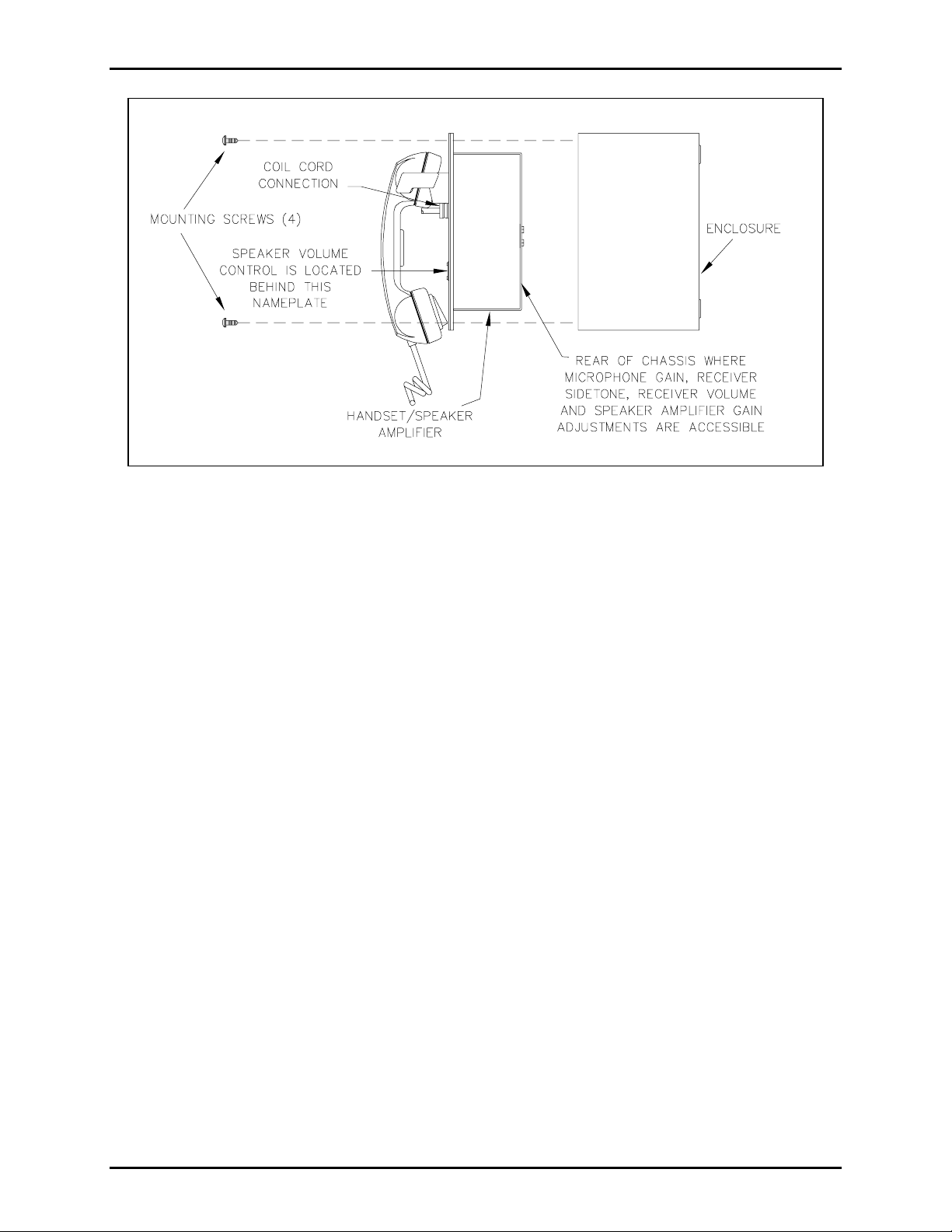
Figure 1 shows installation and a djustment det ails. Please refer to the drawing when you are installing and
adjus ting the amplifier.
GAI-Tronics Corporation P.O. Box 1060, Reading, PA 19607-1060 USA
610-777-1374 800-492-1212 Fax : 610-796-5954
ISIT WWW.GAI-TRONICS.COM FOR PRODUCT LITERATURE AND MANUALS
V
Page 2
Model 701-312 Page/ P ar ty
®
600-Ohm Handset/Speaker Amplifier Page: 2 of 5
Pub. 42004-319
Figure 1. I nsta llation and Adjustment Deta ils
Operation
GAI-Tronics offer s two types of P age/P arty® syst ems: single party (one p arty line) and mult i-party (f i ve
party lines) .
Single-Party
To init iate a c all, lift the st ation handset and pres s and hold t he handset p ressb ar. Sp eak direct ly into the
handset to make the p age annou nc ement. The paged individua l lifts the handset of a Page/P arty
for two-way c ommunication over the part y line.
Page/Multi-Party
Complete t he following steps to make a p age annou nc ement:
1. Lift the handset f rom the cr adle.
2. If part y line conversa tion is desired, r otat e t he s elect or swit c h to an unoc c upied pa rty line.
3. Pr es s and hold the handset pressba r.
®
station
4. Speak direct ly into the micr ophone to broadcast your a nnouncement over t he lou dspeakers.
5. Releas e t he handset p ress b ar, and if request ed, wait for a resp onse.
The paged individual(s) responds by picking u p a station hands et and tu rning the select or swit c h to the
requested party line. Party line communica tion, which is full duplex, is not broadcast over the sys tem
spea kers. O ther individual(s) can also pic k up a nd join the convers ation at a ny time. Always ret urn t he
handset to the cradle following a pa ge or a p arty line conversation.
\\s_eng\gtc proddoc s \ s t andard iom s - current release\42004 inst r. m anuals \ 42004-319. doc
3/00
Page 3

Pub. 42004-319
Model 701-312 Page/ P ar ty
®
600-Ohm Handset/Speaker Amplifier Page: 3 of 5
Maintenance
Adjustm en ts
Four adjustments are accessible through the rear chassis of the amplifier using a small standard
scr ewdriver. Each adjustment is clea rly lab eled. The adju stments have been factory- set for optimal
performance. Do not adjust these levels unless you have followed a ll the steps in the Troubleshooting
section and are still not sat i sfied with the s tat ion performance.
• Microphone Gain: adjusts the ga in level from the microp hone s ignal to t he p age or party lines
• Receiver Sid et o n e: the amount of signal t ransmitted from the microp hone to the receiver of a handset
• Receiver Volume: adjusts the ga in level from a part y line t o the receiver
• Speaker Amplifier Gain: adjusts the speaker volume (also acces sible from the front panel)
Troubleshooting
The following table list s some difficulties encountered in Page/ Party® systems. Included are some
tr ou bleshooting hints to aid in remedying these p roblems.
Problem Solution
Any problem with station
perf ormance occ urs .
Spea ker level requir es
adjustment.
Out going c onversation level
requires adju stment.
Incoming convers ation level
requires adju stment.
Review the st ep s of the installation, ens uring t hat you have correctly
followed ALL st eps. C heck all the ter mina tions in the a mplif ier
enclosure and in the line balanc e assembly b efore pr oc eeding to any
other adjustments.
Verify the system’s line balance assembly is a Model 305-002 or that the
existing line balance is set for 600-ohm operation.
1. Adjust the volume contr ol behind the namepla te on the fr ont pa nel.
2. Rep lac e the s peak er or dr i v er.
1. Adjust the microphone gain by removing the amplifier from the
amplifier enclosure and attaching a Model 10440 Series extension
cab l e b et ween t he connectors. Us e a small s tandard screwdriver
1
/8-inch blade) to slowly turn potentiometer (R17) on the rea r
(
chas sis of amplifier u ntil rea c hing the prop er microphone gain.
2. Replace the ha ndset micr ophone.
1. Use a small standard screwdriver to adjust the receiver volume
control on the rear of the amplifier using the Model 10440 Series
extension c able a s descr i bed above.
2. Rep lac e the receiver element in t he h andset.
Feedback/dist ortion ( a hum or
buzz on the line) occurs during
®
all Page/Party
station
operation.
1. Adjust the receiver s i det one on t he rear of the amplifier using t he
rib bon cab l e assembly as described above.
2. The line ma y be improp erly ter mi n ated . In spec t th e system cable for
loose connections, s horts , and grounds. Line balanc e assembly
connections are critical.
\\s_eng\gtc proddoc s \ s t andard iom s - current release\42004 inst r. m anuals \ 42004-319. doc
3/00
Page 4

Model 701-312 Page/ P ar ty
Problem Solution
®
600-Ohm Handset/Speaker Amplifier Page: 4 of 5
Pub. 42004-319
Feedba c k oc c urs only during
page.
Sidetone ( how the operator
hears his own voice) requir es
adjustment.
Use t h e mutin g feature in the a mplifi er enclosure at the t erminal bl o cks.
Connect the violet wire a t ter mina l 8 to terminal 7.
1. Adjust the receiver s i det one at the amplifier, using t he extension
rib bon cable as des c ribed above.
2. Check that t he line balance assembly resistors are connected
properly.
Crosstalk occurs. One or more system cable pairs may be improperly terminated. Visually
inspect the sys tem cable connections for ac c idental cross ing of the ca ble
pairs or grou nds.
Specifications
Amplifier
Power requirements
Voltage.........................................................................90–140 V ac range, 50/60 Hz, 115 V ac nominal
Power consumed: Zero/max. signal (12 watts) .............................................10 VA, 4.5 W/50 VA, 27 W
Construction/finish........ ........................................................ 16-gauge cold-rolled steel/gray baked enamel
Handset
Microphone ........................................................................................................Dynamic, noise-canceling
Receiver........................................................................Dynamic, hearing aid compatible per FCC Part 68
Cable.........................................................................................................Retractile, 6-foot ext ended P VC
Material.....................................................................................................................................Gray ABS
External controls.................................................................................Push-to-page switch or push-to-page
handset pressbar, hands et hook-switch
Handset Amplifier
Output level....................................................................................... 1.5 Vrms nominal into 600 ohm load
Output limiter................................................................................................................. 1. 5 Vrms nominal
Gain................................................................................................... 55 dB nominal (below limiter level);
adjustable from 40 to 63 dB
Frequency response..............................................................................................250–4,000 Hz, +/-1.5 dB
Distortion.................................................................................................. 1.5% maximum THD @ 1 kHz
Controls..............................................................................Microphone gain, receiver volume and sidetone
\\s_eng\gtc proddoc s \ s t andard iom s - current release\42004 inst r. m anuals \ 42004-319. doc
3/00
Page 5

Pub. 42004-319
Model 701-312 Page/ P ar ty
Speaker Amplifier
®
600-Ohm Handset/Speaker Amplifier Page: 5 of 5
Output............................................................................... 12 watts minimum with nominal supply voltage
Voltage gain ............................................................................................................ 26 dB max, adjustable
Frequency response......................................................................... 250–4,000 Hz, +0, -3 dB ref. to 1 kHz
Distortion...................................................................................... 1% maximum THD @ 1 kHz, 12 watts
Input impedance.............................................................................................................50,000 ohms nom.
Controls................................................................................. Speaker volume (adjusted through the access
hole behind the nameplate on the front p anel)
General
Temperature range (operating/storage)............................................... -22º F to +158º F (-30º C to +70º C)
Dimensions..............................................8.1 H × 8.1 W × 3 D inches (20.6 × 20.6 × 7.6 cm) behind panel
8.1 H × 8.1 W × 3.5 D inches (20.6 × 20.6 × 8.9 cm) fr ont of panel
Shipping weight.................................................................................................................6.8 lbs. (3.1 kg)
Replacement Parts
Part Number Description
10112-101 Handset Assembly
13204-002 Receiver Cap
12511-001 Dynamic Transmitter and Cap
12525-001 Pressbar Switch Kit
12514-007 6-foot PVC Cord and Bushing
12514-008 15-foot PVC Cord and Bushing
12514-009 25-foot PVC Cord and Bushing
12514-004 6-foot Hytrel Cord and Bushing
12514-005 15-foot Hytrel Cord and Bushing
12514-006 25-foot Hytrel Cord and Bushing
69701-016 Printed Circuit Board
12523-001 GAI-Tronics Nameplate Kit
12508-005 Amplifier Enclosure Mounting Hardware
12512-008 Hookswitch/Cradle Ass embly K i t
12530-001 Transformer/ Conn. Subassembly
25210-005 Cell Gasket
10440-002 16-pin ribbon cable connector
12604-001 0.7 amp (10 pack)
12604-002 1/16 amp (10 pack)
\\s_eng\gtc proddoc s \ s t andard iom s - current release\42004 inst r. m anuals \ 42004-319. doc
3/00
Page 6

Warranty
Equipment. GAI-Tronics warrants for a period of one (1) year from the date of shipment, that any
GAI-Tronics equipment supplied hereunder shall be free of defects in material and workmanship, shall
comply with the then-current product specifications and product literature, and if applicable, shall be fit
for the purpose specified in the agreed-upon quotation or proposal document. If (a) Seller’s goods prove
to be defective in workmanship and/or material under normal and proper usage, or unfit for the purpose
specified and agreed upon, and (b) Buyer’s claim is made within the warranty period set forth above,
Buyer may return such goods to GAI-Tronics’ nearest depot repair facility, freight prepaid, at which time
they will be repaired or replaced, at Seller’s option, without charge to Buyer. Repair or replacement shall
be Buyer’s sole and exclusive remedy. The warranty period on any repaired or replacement equipment
shall be the greater of the ninety (90) day repair warranty or one (1) year from the date the original
equipment was shipped. In no event shall GAI-Tronics warranty obligations with respect to equipment
exceed 100% of the total cost of the equipment supplied hereunder. Buyer may also be entitled to the
manufacturer’s warranty on any third-party goods supplied by GAI-Tronics hereunder. The applicability
of any such third-party warranty will be determined by GAI-Tronics.
Services. Any services GAI-Tronics provides hereunder, whether directly or through subcontractors,
shall be performed in accordance with the standard of care with which such services are normally
provided in the industry. If the services fail to meet the applicable industry standard, GAI-Tronics will
re-perform such services at no cost to buyer to correct said deficiency to Company's satisfaction provided
any and all issues are identified prior to the demobilization of the Contractor’s personnel from the work
site. Re-performance of services shall be Buyer’s sole and exclusive remedy, and in no event shall GAITronics warranty obligations with respect to services exceed 100% of the total cost of the services
provided hereunder.
Warranty Periods. Every claim by Buyer alleging a defect in the goods and/or services provided
hereunder shall be deemed waived unless such claim is made in writing within the applicable warranty
periods as set forth above. Provided, however, that if the defect complained of is latent and not
discoverable within the above warranty periods, every claim arising on account of such latent defect shall
be deemed waived unless it is made in writing within a reasonable time after such latent defect is or
should have been discovered by Buyer.
Limitations / Exclusions. The warranties herein shall not apply to, and GAI-Tronics shall not be
responsible for, any damage to the goods or failure of the services supplied hereunder, to the extent
caused by Buyer’s neglect, failure to follow operational and maintenance procedures provided with the
equipment, or the use of technicians not specifically authorized by GAI-Tronics to maintain or service the
equipment. THE WARRANTIES AND REMEDIES CONTAINED HEREIN ARE IN LIEU OF AND
EXCLUDE ALL OTHER WARRANTIES AND REMEDIES, WHETHER EXPRESS OR IMPLIED BY
OPERATION OF LAW OR OTHERWISE, INCLUDING ANY WARRANTIES OF
MERCHANTABILITY OR FITNESS FOR A PARTICULAR PURPOSE.
Return Policy
If the equipment requires service, contact your Regional Service Center for a return authorization number
(RA#). Equipment should be shipped prepaid to GAI-Tronics with a return authorization number and a
purchase order number. If the equipment is under warranty, repairs or a replacement will be made in
accordance with the warranty policy set forth above. Please include a written explanation of all defects to
assist our technicians in their troubleshooting efforts.
Call 800-492-1212 (inside the USA) or 610-777-1374 (outside the USA) for help identifying the
Regional Service Center closest to you.
(Rev. 10/06)
 Loading...