

Page 1

Pub.:42004-397G
GAI-TRONICS® CORPORATION
A HUBBELL COMPANY
VoIP Telephones
TABLE OF C ONTENTS
Getting Started.................................................................................................................................1
Product Overview...................................................................................................................................1
System Requirements and Limitations.................................................................................................2
Tips for VoIP Subscribers...................................................................................................................... 2
Features and Functions..........................................................................................................................2
Operation.........................................................................................................................................3
Placing an Emergency Call from a VoIP Phone .................................................................................. 3
Models 293-700, 293AL-700, 294AL-702, 297-700, 297-701 & 298-702..........................................................3
Placing a Non-Emergency Call..............................................................................................................3
Models 294AL-702, 298-701 & 298-702 .............................................................................................................3
Models 297-701, 297-702 and 297-703................................................................................................................3
Americans with Disabilities Act (ADA) Functionality.........................................................................3
Installation ......................................................................................................................................4
General Information..............................................................................................................................................4
Safety Guidelines.....................................................................................................................................4
Station Placement .................................................................................................................................................4
Tamper-Resistant Hardware .................................................................................................................................4
Conduit Installation Details ..................................................................................................................................5
Models 293-700, 293AL-700, and 294AL-702.......................................................................................6
VoIP Flush-Mount Telephones..............................................................................................................8
Setup..............................................................................................................................................11
Field Wire installation.......................................................................................................................... 11
Power..................................................................................................................................................................12
Network Cable....................................................................................................................................................12
I/O.......................................................................................................................................................................12
Recommended Cabling.......................................................................................................................................12
Connecting a Beacon.............................................................................................................................13
Hardware Configuration......................................................................................................................14
Mic Bias..............................................................................................................................................................14
Handset Enable...................................................................................................................................................14
Inductive Loop Source........................................................................................................................................14
Status Indication...................................................................................................................................14
Power..................................................................................................................................................................14
Heartbeat .............................................................................................................................................................14
Internal Controls...................................................................................................................................15
Speaker Level- Local Control.............................................................................................................................15
GAI-Tronics Corporation 400 E. Wyomissing Ave. Mohnton, PA 19540 USA
610-777-1374 800-492-1212 Fax: 610-796-5954
V
ISIT WWW.GAI-TRONICS.COM FOR PRODUCT LITERATURE AND MANUALS
Page 2

PUB. 42004-397G
V
OIP TELEPHONES PAGE ii
Speaker Level- Remote Control.......................................................................................................................... 15
Programming ................................................................................................................................16
Quick Start Guide.................................................................................................................................16
Alternative Configuration Methods....................................................................................................17
Maintenance..................................................................................................................................18
General Information............................................................................................................................. 18
Preventive Maintenance for Models 297-70x and 298-70x................................................................18
Cleaning..............................................................................................................................................................18
Prevention...........................................................................................................................................................18
Service.................................................................................................................................................... 18
Troubleshooting....................................................................................................................................19
Specifications ................................................................................................................................20
Replacement Parts................................................................................................................................22
Confidentiality Notice...................................................................................................................23
GAI-Tronics Corporation 400 E. Wyomissing Ave. Mohnton, PA 19540 USA
610-777-1374 800-492-1212 Fax: 610-796-5954
V
ISIT WWW.GAI-TRONICS.COM FOR PRODUCT LITERATURE AND MANUALS
Page 3

PUB. 42004-397G
GAI-TRONICS® CORPORATION
A HUBBELL COMPANY
VoIP Telephones
Getting Started
Product Overview
Thank you for purchasing a GAI-Tronics Voice Over Internet Protocol (VoIP) telephone. The VoIP
Telephones are designed for connection to a 10/100 baseT Ethernet. These telephones will operate from
Power-over-Ethernet or an external power source. The VoIP Telephones provide direct point-to-point
communications between personnel throughout the facility over the existing LAN.
In addition to providing standard telephone operation, GAI-Tronics VoIP telephones feature real-time
alarm reporting that enables system supervisors to monitor the phones activity and address caller needs or
maintenance issues immediately. Also, four user configurable inputs and two outputs have been provided
for customer use. This manual applies to the following GAI-Tronics VoIP Telephones:
Model Description
293-700
VoIP Phone – This phone is housed in a safety yellow, glass-reinforced polyester
enclosure that is designed to be surface-mounted and includes an emergency push button.
293AL-700
294AL-702
297-700
297-701
297-702
297-703
298-701
298-702
VoIP Phone – The vandal-resistant phone is housed in a cast aluminum enclosure painted
safety yellow that is designed to be surface-mounted and includes an emergency push
button.
VoIP Phone with Keypad – A cast aluminum enclosure painted safety yellow that is
designed to be surface-mounted and includes a 12-button Braille keypad, an emergency
push button and a call (off-hook) button.
Flush-panel VoIP Phone – This is a flush-mount phone with a heavy-gauge brushed
stainless steel front panel, and includes an emergency autodial push button.
Flush-panel VoIP Phone – This is a flush-mount phone with a heavy-gauge brushed
stainless steel front panel, and includes an emergency autodial push button and a call (offhook) autodial button.
Flush-panel VoIP Phone – This is a flush-mount phone with a heavy-gauge brushed
stainless steel front panel, and includes two call (off-hook) autodial buttons.
Flush-panel VoIP Phone – This is a flush-mount phone with a heavy-gauge brushed
stainless steel front panel, and includes three call (off-hook) autodial buttons.
Flush-panel VoIP Phone with Keypad – This is a flush-mount phone with a heavy-gauge
brushed stainless steel front panel, and includes a 12-button Braille keypad and a call
(off-hook) autodial button.
Flush-panel Emergency Phone with Keypad – This flush-mount phone with a heavygauge brushed stainless steel front panel includes a 12-button Braille keypad, an
emergency push button, and a call (off-hook) button.
GAI-Tronics Corporation 400 E. Wyomissing Ave. Mohnton, PA 19540 USA
610-777-1374 800-492-1212 Fax: 610-796-5954
V
ISIT WWW.GAI-TRONICS.COM FOR PRODUCT LITERATURE AND MANUALS
Page 4

PUB. 42004-397G
V
OIP TELEPHONES PAGE 2 of 23
All of the listed VoIP Telephones, except for Models 297-702, 297-703 and 298-701 comply with the
Americans with Disabilities Act (ADA). Each phone includes a Braille tag for vision-impaired
individuals to identify the functions of the telephone and a visual indication for hearing-impaired
individuals indicating that an emergency call has been answered.
The GAI-Tronics VoIP Phone product line provides the flexibility to address a diverse range of
applications. A wide variety of functions can be achieved by altering the configuration data stored in the
phone’s non-volatile memory. The telephone configuration options include:
• Web pages
• Configuration file
• Command Line Interface (CLI)
System Requirements and Limitations
Each VoIP Telephone requires Power-over-Ethernet or a local 48 V dc power source for operation. Two
VoIP telephones can be connected in a peer-to-peer configuration without the need for a LAN. However,
a 10/100 baseT Ethernet with SIP Server is required for systems containing three or more VoIP
Telephones. Conferences are limited by the customer’s LAN media capabilities and the services
available at each end point.
Tips for VoIP Subscribers
If you have or are thinking of subscribing to an interconnected VoIP service, you should:
• Provide your accurate physical address to your interconnected VoIP service provider to ensure that
emergency services can quickly be dispatched to your location.
• Be familiar with your VoIP service provider’s procedures for updating your address, and promptly
update address information in the event of a change.
• Have a clear understanding of any limitations of your 911 service.
• Inform children, babysitters, and visitors about your VoIP service and its 911 limitations, if any.
• If your power is out or your internet connection is down, be aware that your VoIP service may not
work. Consider installing a backup power supply, maintaining a traditional phone line, or having a
wireless phone as a backup.
• If you have questions about interconnected VoIP and 911 or about VoIP in general, see
http://www.fcc.gov/cgb/consumerfacts/voip.html.
Features and Functions
The voice-over-internet protocol (VoIP) hands-free versions include the following features:
• SIP compatible (RFC3261)
• Automatic call divert (memory list)
• Weather and vandal resistant
• Real-time alarm reporting via email or Syslog
• Power-over-Ethernet com p atib le
• Configurable via web page, serial link or download
• Four auxiliary inputs, two volt-free contact outputs
f:\standard ioms - current release\42004 instr. manuals\42004-397g.doc
11/09
Page 5

PUB. 42004-397G
V
OIP TELEPHONES PAGE 3 of 23
Operation
Placing an Emergency Call from a VoIP Phone
Models 293-700, 293AL-700, 294AL-702, 297-700, 297-701 & 298-702
To place an emergency call:
1. Press the E
MERGENCY push button to place an immediate call to a preprogrammed emergency
number, typically a security office or 911.
2. As the factory default, the C
ALL RECEIVED WHEN LIT LED will light steady when the call is
answered.
Placing a Non-Emergency Call
Models 294AL-702, 298-701 & 298-702
To place a non-emergency call:
1. Press the C
2. Wait for dial tone.
3. Use the keypad to dial the desired number.
4. At the end of the conversation, press the C
Models 297-701, 297-702 and 297-703
To place a non-emergency autodial call:
1. Press the black autodial push button to place an immediate call to a preprogrammed number.
ALL push button.
ALL push button again to put the phone on-hook.
2. On the Model 297-701 only, the C
ALL RECEIVED WHEN LIT LED will light steady when the call is
answered.
Receiving a Call
When a VoIP Emergency Telephone is called, the phone automatically goes off-hook and a conversation
can take place.
Disconnecting Calls
There are both manual and automatic methods included in the VoIP emergency telephones to disconnect
calls. The disconnect methods include the following:
• To manually disconnect a non-emergency call, press the C
ALL button a second time.
• To automatically disconnect; the user must wait for the maximum call duration timeout.
Americans with Disabilities Act (ADA) F unctionality
The CALL RECEIVED WHEN LIT lamp indicates to hearing-impaired individuals that the emergency call
has been answered. When the individual presses the emergency push button and the person receiving the
call answers, the telephone illuminates the C
ALL RECEIVED WHEN LIT lamp.
f:\standard ioms - current release\42004 instr. manuals\42004-397g.doc
11/09
Page 6

PUB. 42004-397G
V
OIP TELEPHONES PAGE 4 of 23
Installation
General Information
WARNING
This product can contain hazardous voltages. Always remove power to this
station and any associated equipment before beginning any installation.
CAUTION
Do not install this equipment in areas other than those indicated on the
approval listing in the Specification section of this manual. Such installation may cause a safety
hazard and consequent injury or property damage.
Install equipment without modification and according to all applicable local and national electrical codes.
Consult the National Electrical Code (NFPA 70), Canadian Standards Association (CSA 22.1), and local
codes for specific requirements regarding your installation. Class 2 circuit wiring must be performed in
accordance with NEC 725.55.
Safety Guidelines
When installing any GAI-Tronics equipment, ple ase ad here to the fol lowi ng guidel ines to ensu re the
safety of all personnel:
• Do not install wiring during a lightning storm.
• Electrostatic Discharge (ESD) Protection: Your VoIP telephone may have an earth ground terminal
provision. If so, ensure that it is connected to ground in accordance with all local safety regulations
and the National Electrical Code (NEC). Grounding has to be ensured for safe and stable
communications. Do not use long and coiled ground wires. Trim ground wires to the required
length. Use a star configuration whenever possible. Please note proper grounding does not eliminate
the need for lightning protection for the telephone or the telephone system.
• Do not install jacks in wet locations unless the jack is specifically designed for wet locations.
Station Placement
To prevent feedback problems in the system, volume settings, and station placement must be taken into
consideration. Unpleasant feedback problems can be reduced by:
• Pointing the telephone away from other telephones located nearby
• Reducing volume levels
Tamper-Resistant Hardware
All of the telephones described in this manual are vandal resistant. The front panel for each telephone
covered in this manual is attached to its enclosure with tamper-resistant screws. A GAI-Tronics Model
233-001 Tamper-Resistant Screwdriver (sold separately) is recommended for installing the tamperresistant screws.
f:\standard ioms - current release\42004 instr. manuals\42004-397g.doc
11/09
Page 7

PUB. 42004-397G
V
OIP TELEPHONES PAGE 5 of 23
Conduit Installation Details
GAI-Tronics recommends installing telephone lines in conduit to protect against accidental damage and
vandalism. To prevent moisture from entering the enclosure, we strongly recommend the following:
• Conduit should enter the enclosure from the bottom.
• Sealed fittings should be installed at all cable entry points.
• Silicone sealant or equivalent should be applied around and inside all conduit entries.
Please refer to the examples below for the recommended conduit installation details.
Figure 1. Bottom entry conduit recommended for
non-metallic enclosures
Figure 3. Bottom entry conduit installation details
for metallic enclosures
Figure 2. Top entry conduit installation for non-
metallic enclosures (NOT recommended)
Figure 4. Top entry conduit installation details for
metallic enclosures (NOT recommended)
f:\standard ioms - current release\42004 instr. manuals\42004-397g.doc
11/09
Page 8
PUB. 42004-397G
V
OIP TELEPHONES PAGE 6 of 23
Models 293-700, 293AL-700, and 294AL-702
The mounting and wiring instructions for Models 293-700, 293AL-700 and 294AL-702 are as follows:
1. Remove the four tamper-resistant screws from
the front panel.
2. Position the enclosure on the mounting
surface. The enclosure provides four
0.28-inch mounting holes. Secure it with the
four ¼-inch diameter bolts of the appropriate
length for the mounting surface.
OTE: When using the GAI-Tronics Model
N
231-001 Pole Mounting Kit, follow the
mounting instructions provided in the kit.
3. For Model 293-700 only: Create an access
hole using a Greenlee-type punch that is
equivalent in size to the conduit diameter.
Bottom entry is strongly recommended. Insert
Figure 5. Model 293-700 VoIP Phone in a Non-
metallic Enclosure
a conduit fitting in the access hole. Refer to
conduit installation details on page 5.
N
OTE: Use silicone sealant or equivalent
around and inside all conduit entries.
4. Pull the cable through the conduit. Install the cable as shown in the Field Wire Installation section on
page 11.
5. Make hardware configuration changes, if necessary. Refer to page 14 for more information.
6. Perform the initial programming of the phone. Refer to the Programming section on page 16. Verify
that the phone is operating properly by calling to and from another phone.
7. Adjust the speaker levels if necessary. Refer to the Speaker Level section on page 15.
8. Complete the installation by attaching the front panel assembly to the rear enclosure using the four
tamper-resistant screws.
f:\standard ioms - current release\42004 instr. manuals\42004-397g.doc
11/09
Page 9

PUB. 42004-397G
V
OIP TELEPHONES PAGE 7 of 23
Figure 6. Model 293AL-700
Figure 7. Model 294AL-702
Figure 8. Component Locations for Models 293-700, 293AL-700, and 294AL-702
f:\standard ioms - current release\42004 instr. manuals\42004-397g.doc
11/09
Page 10

PUB. 42004-397G
V
OIP TELEPHONES PAGE 8 of 23
VoIP Flush-Mount Telephones
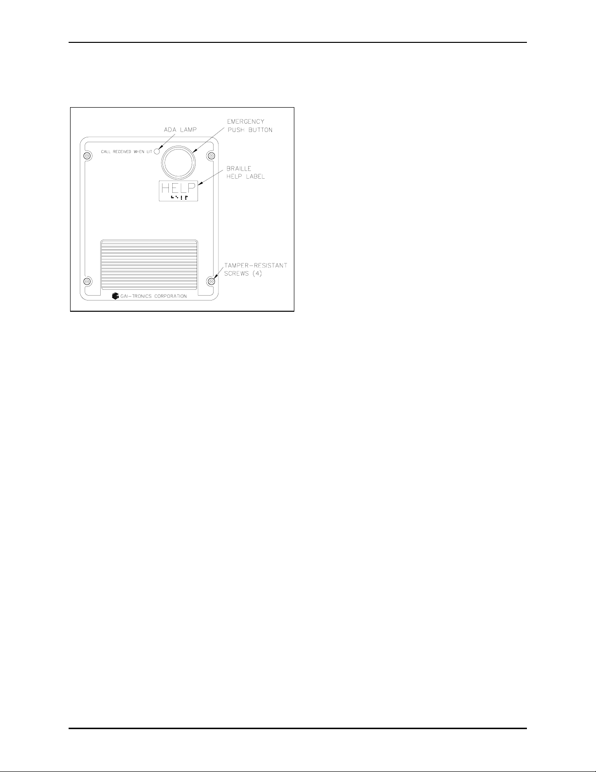
Figure 9. Model 297-700
Figure 10. Model 298-702
Stanchion or Flush-mount Applications
1. Use the supplied back box to mount the Model 297-700, 297-701, 297-702, 297-703, 298-701 and
298-702 VoIP Telephones in flush-mount applications or in a GAI-Tronics Model 234 Series
Stanchion. Mount the back box to the structure using the appropriate hardware. Refer to Figure 15
cutout dimensions.
2. Remove the tapered plug from the top or bottom cable entry hole in the back box, and install the cable
and cable fitting. See the Field Wire Installation section on page 11.
3. Make hardware configuration changes, if necessary. Refer to page 14.
4. Perform the initial programming of the phone. Refer to the Programming section beginning on page
16. Verify operation by calling to and from another phone.
5. Adjust the speaker levels if necessary. Refer to the Speaker Level section on page 15.
6. Attach the telephone’s front panel to the mounting flanges of the back box using the six supplied
#10-32 tamper-resistant screws and washers.
f:\standard ioms - current release\42004 instr. manuals\42004-397g.doc
11/09
Page 11

PUB. 42004-397G
V
OIP TELEPHONES PAGE 9 of 23
Figure 11. Model 297-701
Figure 13. Model 297-703
Figure 12. Model 297-702
Figure 14. Model 298-701
f:\standard ioms - current release\42004 instr. manuals\42004-397g.doc
11/09
Page 12

PUB. 42004-397G
V
OIP TELEPHONES PAGE 10 of 23
Figure 15. Flush-Mount VoIP Telephone Mounting Details
f:\standard ioms - current release\42004 instr. manuals\42004-397g.doc
11/09
Page 13

PUB. 42004-397G
V
OIP TELEPHONES PAGE 11 of 23
Setup
Field Wire installation
After all the field wires are pulled through the rear enclosure, install all connections as indicated below.
Refer to Figure 16 for wiring details. Refer to Table 1 on page 12 for the recommended conductor sizes.
N
OTE: Consult the National Electrical Code (NFPA 70), Canadian Standards Association (CSA 22.1),
and local codes for the specific requirements regarding your installation. Install all equipment without
modification and according to the local and national codes. Class 2 circuit wiring must be performed in
accordance with NEC 725.55.
Figure 16. VoIP Phone PCB Assembly
f:\standard ioms - current release\42004 instr. manuals\42004-397g.doc
11/09
Page 14

PUB. 42004-397G
V
OIP TELEPHONES PAGE 12 of 23
Power
Power-Over-Etherne t (POE)
Connect power to the system as indicated in your POE equipment manual.
Local Power
When POE is not available, this telephone can operate from a local 48 V dc power source. A removable
terminal block P11 has been provided for connection of local power to the telephone. Connect the
positive conductor to the (+) terminal and the negative conductor to the (-) terminal of P11.
Ground
The enclosure of each phone must be connected to earth ground. Install a #6 ring lug on the ground
conductor prior to connection to the ground screw located on the rear of the front panel.
Network Cable
Connect a Cat5 or Cat5e UTP cable with an RJ45 connector between the Local Area Network (LAN) and
the VoIP PCBA.
I/O
Inputs
Four auxiliary inputs have been provided for customer use. Terminations for these inputs are provided on
terminal block TB1. Connect each input between the desired input (INPUT 1-4) and common (COM) on
terminal block TB1. Please refer to the Inputs section of Pub. 42004-396 for programming instructions
for these inputs.
Outputs
Two outputs have been provided for customer use. Terminations for these outputs are provided on
connector P1. Output 1 is a single pole, N.O. contact. Output 2 is a single pole with both a N.O. and
N.C. contact. Please refer to the Outputs section of Pub. 42004-396 for programming instructions for
these outputs.
Recommended Cabling
Table 1. Recomm ended Cabling
Cable Use Size
LAN Cat5 or Cat5e UTP cable with an RJ45 connector
Power 2-conductor, No. 22 AWG is typical
Inputs 2-conductor, No. 22 AWG is typical
Output contacts 2 or 3-conductor, No. 18 AWG is typical
f:\standard ioms - current release\42004 instr. manuals\42004-397g.doc
11/09
Page 15

PUB. 42004-397G
V
OIP TELEPHONES PAGE 13 of 23
Connecting a Beacon
Each phone includes two solid state relays. Contact 1 on P1 of the VoIP Carrier PCBA provides the
connections for a beacon output. Refer to Figure 17 for the connection details.
Contact 1 allows peripheral equipment, such as beacons, video cameras, and alarm generators, to be
activated when the E
the emergency call.
In many applications, the output is used to operate a GAI-Tronics Model 530-001/531A Beacon (sold
separately). For connection details, please refer to the Model 530-001/531A installation instructions
included with the beacon. Information is also available at www.gai-tronics.com
MERGENCY push button is pressed. The relay remains energized for the duration of
.
Figure 17. Model 297-700 and 298-701 - Component Locations
(shown with connection to optional GAI-Tronics 530-001/531A Beacon)
f:\standard ioms - current release\42004 instr. manuals\42004-397g.doc
11/09
Page 16

PUB. 42004-397G
V
OIP TELEPHONES PAGE 14 of 23
Hardware Configuration
Mic Bias
Configuration jumper P22 has been provided to enable/disable the bias to the microphone. Set the MIC
BIAS to Y for hands-free telephones, and to N for handset telephones.
Handset Enable
Configuration jumper P29 has been provided to enable audio from the handset microphone only. Set the
Handset Enable (HNDST) jumper to Y for handset telephones and to N for hands-free telephones. This
jumper will be factory set for proper default operation.
Inductive Loop Source
Configuration jumper P19 has been provided to set the Inductive Loop Source. Set the Inductive Loop
Source to SPKR for hands-free telephones, and to EAR for handset telephones.
Status Indication
Power
The Power LED located on the VoIP PCBA illuminates when power is applied to the telephone.
Heartbeat
The Heartbeat LED located on the VoIP PCBA will flash once communication over the LAN is
established.
f:\standard ioms - current release\42004 instr. manuals\42004-397g.doc
11/09
Page 17

PUB. 42004-397G
V
OIP TELEPHONES PAGE 15 of 23
Internal Controls
Speaker Level- Local Control
A post header, P14, has been provided for adjustment of the speaker volume. The speaker volume
adjustment operates as follows:
• The initial direction of the volume (increase or decrease) is determined by prior activity. The initial
direction will be opposite to that of the previous activity.
• Changing the direction is accomplished by allowing a period of inactivity (open across P14) for
greater than 1 second or by moving the wiper to the end of the potentiometer range.
Example /Volume Increase:
Short across P14. The volume begins to decrease. Remove short across P14
and wait 1 second. Short across P14 again. The volume begins to increase. Remove short across P14
when the desired volume has been reached.
P14 can also be used as an optional front panel volume control switch.
Speaker Level- Remote Control
The speaker volume level can also be controlled remotely by changing the setting in the configuration
file. Please refer to the Speaker Volume section of Pub. 42004-396 for programming instructions.
OTE: The local speaker volume setting using P14 should be set for the maximum volume (factory
N
default) prior to adjusting the speaker volume remotely.
Figure 18. VoIP Carrier PCBA Component Locations
f:\standard ioms - current release\42004 instr. manuals\42004-397g.doc
11/09
Page 18

PUB. 42004-397G
V
OIP TELEPHONES PAGE 16 of 23
Programming
Refer to Pub. 42004-396, VoIP Telephone Configuration Guide for detailed programming and
configuration instructions .
Quick Start Guide
The general sequence for set up and use is:
Stage of Process Comments
Initial network configuration Essential: Each phone must be set up for the network prior to
installation.
Assign a host name Recommended: The host name provides identification of the different
VoIP phones on the network.
Change user name and
password
Recommended: This security measure help s to prev ent unautho riz ed
changes to the phone’s configuration.
Mounting Physically mount the phone at the intended location.
Installation Provide phone connections and cabling to the network at the intended
location.
Final configuration (can also
be done prior to installation)
Set the autodial numbers, etc. Configuration changes can be performed
remotely, if desired.
Test Verify that calls can be made successfully.
Maintain Monitor alarms. Set up auto-updates.
The easiest way to get started is to make a network connection to the unit and log on via a web browser.
The unit is initially set with a static IP address:
IP address 192.168.1.2
A user name and password will be requested. The initial factory settings are:
User Name user
Password password
The phone’s home page is as shown below, and allows access to all the other configuration pages. Use
the Network page to change IP settings appropriate for the intended network.
f:\standard ioms - current release\42004 instr. manuals\42004-397g.doc
11/09
Page 19

PUB. 42004-397G
V
OIP TELEPHONES PAGE 17 of 23
ATTENTION
Be sure to assign a unique host name (located on the UNIT settings page) for
each telephone on the network. The factory default host name in each unit is its serial number prefixed by
“GT”.
Full help is available from: www.gai-tronics.co.uk/voipsupport.htm
A CD containing all help files and the configuration file tool is available from GAI-Tronics on request.
Alternative Configuration Methods
There are three methods for configuring GAI-Tronics VoIP telephones:
• Web pages
• Configuration file
• Command Line interface (CLI)
Web pages (held within the telephone) can be accessed over the network using a browser such as Internet
Explorer™, to view and change settings within a single unit.
Configuration files are ASCII text files containing configuration options that can be read and edited by
VCONF (a dedicated software configuration tool), or directly by a knowledgeable user. The telephone
can automatically download a configuration file from the network, providing a controlled method of
configuring multiple telephones.
The telephone can also be configured using a command line interface, either via the local serial port or
remotely via a TELNET session over the network.
VCONF and the complete syntax and command structures of configuration files and the CLI are available
as free downloads from www.gai-tronics.co.uk/voipsupport.htm
request from GAI-Tronics.
, and are also available on a CD on
f:\standard ioms - current release\42004 instr. manuals\42004-397g.doc
11/09
Page 20

PUB. 42004-397G
V
OIP TELEPHONES PAGE 18 of 23
Maintenance
WARNING
This product can contain hazardous voltages. Always remove power to this
station prior to servicing.
General Information
1. Inspect and replace frayed or cracked wiring.
2. Secure/replace loose wires and terminal lugs.
3. Remove corrosion from terminals.
4. Inspect fuse F1 on the VoIP Carrier PCBA.
Preventive Maintenance for Models 297-70x and 298-70x
Stainless steel does require maintenance to prevent corrosion from occurring. Different installation
locations may require more regular maintenance than others, depending on the environment and exposure
to airborne contaminants. The following maintenance steps should be performed on a regular basis or
when corrosion is first noticed on your Model 297-70x and 298-70x Telephones.
Cleaning
For general cleaning, wipe surface with a cleanser or cleanser and water mixture. Any cleanser that is
safe for glass is usually safe for stainless steel. Wipe dry.
If corrosion or rusting is noticed, remove with a non-abrasive commercial cleanser and water. Rub
stained areas in the same direction as the existing grain. Stubborn stains may be removed with a paste
made from magnesium oxide, ammonia, and water. Wipe clean with water rinse and dry.
Prevention
Automotive wax provides the best results in preventing corrosion on stainless steel. Simply apply wax,
let dry to a haze, and buff to a shine with a clean dry cloth. This application should protect the telephone
surface for many months as it will allow naturally re-formation of the chromium oxide layer.
DO NOT use steel wool, sandpaper, mineral acids, bleaches, or chlorine cleansers on the stainless steel.
Service
If your GAI-Tronics phone requires service, contact your Regional Service Center for a return
authorization number (RA#). Equipment should be shipped prepaid to GAI-Tronics with a return
authorization number and a purchase order number. If the equipment is under warranty, repairs will be
made without charge. Please include a written explanation of all defects to assist our technicians in their
troubleshooting efforts.
Call 800-492-1212 inside the USA or 610-777-1374 outside the USA for help identifying the Regional
Service Center closest to you.
f:\standard ioms - current release\42004 instr. manuals\42004-397g.doc
11/09
Page 21

PUB. 42004-397G
V
OIP TELEPHONES PAGE 19 of 23
Troubleshooting
Problem Possible Solution
Low volume Increase the volume settings using button P14 on the VoIP Carrier PCBA.
If the volume setting is still low, increase the volume level in the
telephone's configuration.
High volume Decrease the volume settings using button P14 on the VoIP Carrier PCBA.
If the volume setting is still high, decrease the volume level in the
telephone's configuration.
Front panel push buttons
Verify the pushbuttons are properly configured.
are not operational
Inputs not operational Check the input connections.
Verify the inputs are properly configured.
Outputs not operational Check the output connections.
Verify the outputs are properly configured.
Cannot make or receive
calls
Check the connection of the LAN cable.
Verify that power is applied to the unit.
Verify the LAN parameters have been configured properly.
Verify the phone has been set up on the network.
No power indication Check the power connections.
If using POE, check the operation of the POE equipment.
Feedback 1. Point the speakers away from the interfering station.
2. Reduce the speaker volume.
3. Increase the distance between the speaker and the interfering station.
f:\standard ioms - current release\42004 instr. manuals\42004-397g.doc
11/09
Page 22

PUB. 42004-397G
V
OIP TELEPHONES PAGE 20 of 23
Specification s
Power...................................................................... Power-over-Ethernet, 802.3af compliant (via RJ45), or
External power supply - 36–56 V dc, 200 mA
A separate, isolated supply must be provided for each telephone.
Network ............................................................................10/100 BaseT Ethernet RJ45, Cat5 or Cat5e UTP
Static IP provisioning or DHCP STUN client (NAT traversal)
Call Control Signaling ...................................................................SIP (RFC3261 compliant) Loose routing
Microphone, Electret......................................................................................................................13507-005
Inputs
Keypad*.......................................................................................................................................3 × 4 matrix
Push buttons*........................................................................................ Call, Autodial, Emergency Autodial
Configurable inputs.......................................................................................................................................4
Outputs
Output 1 .....................................................................................................8 A @ 30 V ac/dc (resistive load)
Output 2 .....................................................................................................5 A @ 30 V ac/dc (resistive load)
Controls
External*.............................................................................................................Keypad, push-button inpu ts
Internal.....................................................................Speaker volume, mic bias, reset switch, handset enable
Indicators
External............................................................................................................................. Call received LED
Internal......................................................................................................Power, Heartbeat, & EACT LEDs
Audio output.........................................................................90 dB SPL or greater @ 0.5 meters (@ 1 kHz)
Codecs and audio......................................................................................................................G.711 A-Law
G.711 µ-Law
G.722
G.729
G.723.1 MP-MLQ
G.723.1 ACELP
Codec preference sequence
DTMF in-band / out-of-band (RFC2833)
Configurable comfort tones (to em ulate nat ional tone s)
Configuration...............................................................................................................Embedded web server
Embedded Telnet server
Configuration file download
Configuration file building tool (Vconf.exe)
Direct serial connection
(9-way D-type female connector)
Command line interface
SNTP with time zone and daylight saving
Automatic updating via TFTP
Password protection
*Not available on all models.
f:\standard ioms - current release\42004 instr. manuals\42004-397g.doc
11/09
Page 23

PUB. 42004-397G
V
OIP TELEPHONES PAGE 21 of 23
Monitoring and reporting............................Real-time over TCP/IP proprietary Syslog application or email
Embedded SMTP client
Automatic fault report ing
Call Diversion...................................................................................Configurable call lists (max 20 entries)
Numbers or URIs (with comfort tones)
Divert to next in list if the call fails
Compliance to Standards...............................................................................................FCC CRF 47 Part 15
Mechanical
Temperature range
Operating...........................................................................................-4º F to +140º F (-20º C to +60º C)
Storage............................................................................................................................-40º C to +70º C
Relative humidity............................................................................................... Up to 95%, non-condensing
PCBA (printed circuit board assembly)............................................................................. Conformal coated
Model 293-700
Enclosure construction..................... Valox (high impact, glass-reinforced polyester) painted safety yellow
Dimensions ............................................................. 9.5 H × 8 W × 4 D inches (241.3 × 203.2 × 101.6 mm)
Weight................................................................................................................................................. 4.0 lbs.
Models 293AL-700 and 294AL-702
Enclosure construction.........................................................................Cast aluminum painted safety yellow
(Model 294AL-702 only) Braille dial pad.................................................................Chrome-plated zinc
Dimensions ............................................................. 9.5 H × 8 W × 4 D inches (241.3 × 203.2 × 101.6 mm)
Weight
Model 293AL-700........................................................................................................................ 7.8 lbs.
Model 294AL-702........................................................................................................................ 8.5 lbs.
Models 297-700, 297-701, 297-702, 297-703, 298-701 and 298-702
Construction
Panel..................................................................................... 14-gauge, type 304 brushed stainless steel
Back box....................................................... 16-gauge cold-rolled steel with black polyurethane finish
(Model 298-702 only) Braille dial pad......................................................................Chrome-plated zinc
Dimensions
Panel.................................................................................... 12.0 H × 10.0 W inches (304.8 × 254 mm )
Back box (depth from mounting surface)............................................................ 2.38 inches (60.5 mm)
Panel Cutout................................................................. 10.1 H × 8.43 W inches (255.57 × 214.12 mm)
Weight
Model 297-700............................................................................................................................. 6.5 lbs.
Model 297-701............................................................................................................................. 6.5 lbs.
Model 297-702............................................................................................................................. 6.5 lbs.
Model 297-703............................................................................................................................. 6.5 lbs.
Model 298-701............................................................................................................................. 7.2 lbs.
Model 298-702............................................................................................................................. 7.2 lbs.
f:\standard ioms - current release\42004 instr. manuals\42004-397g.doc
11/09
Page 24

PUB. 42004-397G
V
OIP TELEPHONES PAGE 22 of 23
Replacement Parts
Part No. Description
233-001 Model 233-001 Tamper-Resistant Screwdriver
69841-001 VoIP Carrier PCBA
100-02-
7013-000
51035-005 PCBA, Keypad, metallic
28299-007 Tamper-resistant Screws (Flush-mount models)
28229-004 Tamper-resistant Screws, 1-1/8 inch
12520-006 Push Button Replacement Kit (1.5-inch, Red)
12520-007 Push Button Replacement Kit (Black)
12521-002 Microphone Replacement Kit
12521-003 Microphone Replacement Kit
12522-006 Piezo Speaker Replacement Kit
12522-005 Piezo Speaker Replacement Kit
21245-003 Terminal Block Connector, 2-Position (External Power)
VoIP Circuit PCBA
293
-700
293AL-
700
294AL-
702
297
-700
297
-701
297
-702
297
-703
298
-701
298
-702
21245-004 Terminal Block Connector, 6-Position (Outputs)
62317-208 8-Point Connector (Inputs)
f:\standard ioms - current release\42004 instr. manuals\42004-397g.doc
11/09
Page 25

PUB. 42004-397G
V
OIP TELEPHONES PAGE 23 of 23
Confidential ity Notice
This manual is provided solely as an installation, operation, and maintenance guide and contains sensitive
business and technical information that is confidential and proprietary to GAI-Tronics. GAI-Tronics
retains all intellectual property and other rights in or to the information contained herein, and such
information may only be used in connection with the operation of your GAI-Tronics product or system.
This manual may not be disclosed in any form, in whole or in part, directly or indirectly, to any third party.
f:\standard ioms - current release\42004 instr. manuals\42004-397g.doc
11/09
Page 26

Warranty
Equipment. GAI-Tronics warrants for a period of one (1) year from the date of shipment, that any
GAI-Tronics equipment supplied hereunder shall be free of defects in material and workmanship, shall
comply with the then-current product specifications and product literature, and if applicable, shall be fit
for the purpose specified in the agreed-upon quotation or proposal document. If (a) Seller’s goods prove
to be defective in workmanship and/or material under normal and proper usage, or unfit for the purpose
specified and agreed upon, and (b) Buyer’s claim is made within the warranty period set forth above,
Buyer may return such goods to GAI-Tronics’ nearest depot repair facility, freight prepaid, at which time
they will be repaired or replaced, at Seller’s option, without charge to Buyer. Repair or replacement shall
be Buyer’s sole and exclusive remedy. The warranty period on any repaired or replacement equipment
shall be the greater of the ninety (90) day repair warranty or one (1) year from the date the original
equipment was shipped. In no event shall GAI-Tronics warranty obligations with respect to equipment
exceed 100% of the total cost of the equipment supplied hereunder. Buyer may also be entitled to the
manufacturer’s warranty on any third-party goods supplied by GAI-Tronics hereunder. The applicability
of any such third-party warranty will be determined by GAI-Tronics.
Services. Any services GAI-Tronics provides hereunder, whether directly or through subcontractors,
shall be performed in accordance with the standard of care with which such services are normally
provided in the industry. If the services fail to meet the applicable industry standard, GAI-Tronics will
re-perform such services at no cost to buyer to correct said deficiency to Company's satisfaction provided
any and all issues are identified prior to the demobilization of the Contractor’s personnel from the work
site. Re-performance of services shall be Buyer’s sole and exclusive remedy, and in no event shall GAITronics warranty obligations with respect to services exceed 100% of the total cost of the services
provided hereunder.
Warranty Periods. Every claim by Buyer alleging a defect in the goods and/or services provided
hereunder shall be deemed waived unless such claim is made in writing within the applicable warranty
periods as set forth above. Provided, however, that if the defect complained of is latent and not
discoverable within the above warranty periods, every claim arising on account of such latent defect shall
be deemed waived unless it is made in writing within a reasonable time after such latent defect is or
should have been discovered by Buyer.
Limitations / Exclusions. The warranties herein shall not apply to, and GAI-Tronics shall not be
responsible for, any damage to the goods or failure of the services supplied hereunder, to the extent
caused by Buyer’s neglect, failure to follow operational and maintenance procedures provided with the
equipment, or the use of technicians not specifically authorized by GAI-Tronics to maintain or service the
equipment. THE WARRANTIES AND REMEDIES CONTAINED HEREIN ARE IN LIEU OF AND
EXCLUDE ALL OTHER WARRANTIES AND REMEDIES, WHETHER EXPRESS OR IMPLIED BY
OPERATION OF LAW OR OTHERWISE, INCLUDING ANY WARRANTIES OF
MERCHANTABILITY OR FITNESS FOR A PARTICULAR PURPOSE.
Return Policy
If the equipment requires service, contact your Regional Service Center for a return authorization number
(RA#). Equipment should be shipped prepaid to GAI-Tronics with a return authorization number and a
purchase order number. If the equipment is under warranty, repairs or a replacement will be made in
accordance with the warranty policy set forth above. Please include a written explanation of all defects to
assist our technicians in their troubleshooting efforts.
Call 800-492-1212 (inside the USA) or 610-777-1374 (outside the USA) for help identifying the
Regional Service Center closest to you.
(Rev. 10/06)
 Loading...