

Page 1

Pub. 42004-378C
GAI-TRONICS® CORPORATION
A HUBBELL COMPANY
Model 293-101, 293-101AL, 297-101,
298-101, and 294-101AL Externally Powered
Emergency Phones
TABLE OF C ONTENTS
Getting Started ........................................................................................................................... 1
Product Overview..............................................................................................................................1
Standard Operation...........................................................................................................................3
Placing an Emergency Call.............................................................................................................................3
Placing a Non-Emergency Call (Models 294-101AL and 298-101 Only)......................................................... 3
Americans with Disabilities Act (ADA) Functionality...................................................................... 4
Installation................................................................................................................................. 5
Safety Guidelines...............................................................................................................................5
General Installation Guidelines.........................................................................................................5
Tamper-Resistant Hardware........................................................................................................................... 5
Conduit Installation Details............................................................................................................................ 6
Models 293-101, 293-101AL, and 294-101AL...................................................................................7
Models 297-101 and 298-101 .............................................................................................................9
Setup ........................................................................................................................................ 12
Hardware Configuration................................................................................................................. 12
Audio Level Adjustments................................................................................................................ 14
Programming...........................................................................................................................15
Remote Programming..................................................................................................................... 15
Local Programming......................................................................................................................... 16
Programming Sequences................................................................................................................. 18
Dialing Options............................................................................................................................................18
Password..................................................................................................................................................... 20
Silent Monitoring Feature............................................................................................................................. 20
Off-Hook Ringing........................................................................................................................................20
Disconnect Options ...................................................................................................................................... 21
Americans with Disa bili ti es Act (ADA) Pr ogramming.................................................................................. 22
Maintenance.............................................................................................................................24
Specifications................................................................................................................. ..........25
GAI-Tronics Corporation P.O. Box 1060, Readi ng, PA 19607-1060 USA
610-777-1374 800-492-1212 Fax: 610-796-5954
ISIT WWW.GAI-TRONICS.COM FOR PRODUCT LITERATURE AND MANUALS
V
Page 2

PUB. 42004-378C
Model 293-101, 293-101AL, 297-101,
298-101, and 294-101AL Externally Powered
Emergency Phones
Getting Started
Product Overview
Thank-you for your purchase of a GAI-Tronics ADA-compliant emergency telephone. This manual
applies to the following GAI-Tronics ADA-Compliant Emergency Telephones:
Model Description
293-101
293-101AL
294-101AL
297-101
298-101
All of the emergency telephones listed above comply with the Americans with Disabilities Act (ADA).
Each phone includes a Braille tag for vision-impaired individuals to identify the functions of the
telephone and a visual indication for hearing-impaired individuals indicating that an emergency call has
been answer ed.
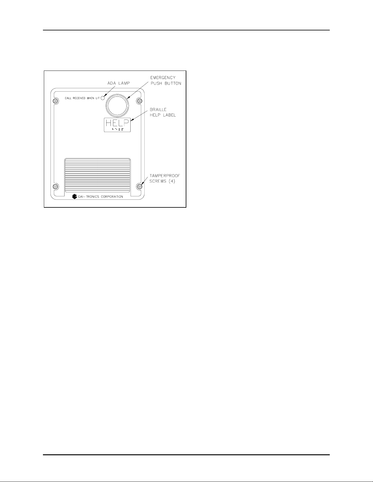
Emergency Phone – This phone is housed in a safety yellow, glass-reinforced polyester
encl osure tha t is design e d to be s urface- mount e d and i nclu des an emer gency push b utt o n.
Emergency Phone – The vandal-resistant phone is housed in a cast aluminum enclosure
painted safety yellow that is designed to be surface-mounted and includes an emergency
push button.
Emergency Phone wi th Keypad – A cast aluminum enclosure painted safety yellow that
is designed to be surface-mounted and includes a 12-button Braille keypad, an emergency
push button and a call (off-hook) button.
Flush-panel Emergency P hone – This is a flush-mount phone with a heavy-gauge
brushed stainless steel front panel, and includes an emergency push button.
Flush-panel Emergency Phone with Keypad – This flush-mount phone with a heavygauge brushed stainless steel front panel includes a 12-button Braille keypad, an
emergency push button, and a call (off-hook) button.
The C
ALL RECEIVED WHEN LIT LED is the visual call- received indica t or . When the security off icer
answers the telephone and acknowledges the call, the LED will light. The LED remains lit until the call
is disconnected.
GAI-Tronics Corporation P.O. Box 1060, Readi ng, PA 19607-1060 USA
610-777-1374 800-492-1212 Fax: 610-796-5954
ISIT WWW.GAI-TRONICS.COM FOR PRODUCT LITERATURE AND MANUALS
V
Page 3

Pub. 42004-378C
XTERNALLY POWERED ADA-COMPLIANT EMERGENCY PHONES PAGE 2 of 28
E
The GAI-Tronics emergency phone product line provides the flexibility to address a diverse range of
applications. A wi de variet y of functions can b e achieved by alteri ng the conf igur atio n data st ored in the
phone’s non-volatile memory. These configuration options include:
• Pre-programmed auto-dial telephone numbers
• Call terminati on method (a utomatic or manua l)
• Maximum call duration
• Ans w erin g options
Each of the above emergency phones require a “Class 2” 12 V dc regulated power supply (included) and
can be connected to any of the following:
• Central Office (CO) line to the Public Switched Telephone Network (PSTN)
• 24 V dc or 48 V dc analog station port of Private Branch Exchange (PBX), Private Automatic Branch
Exchange (PABX) or KSU.
Connection may not be made to pay phone extensions or shared service (party) lines.
OTE: Each telephone req ui res a d edicated powe r s upply. Multiple telephones ca nnot be
N
connected to a si ng le power supp ly. The power supply must p ro v i de g a lvanic isol at ion between its
input a nd it s 12 V dc o utput. For dc - t o -dc app licat ions, g alvanic is olation is requir e d. Galv anic
isolation (separation) is achieved by using a transformer or opto-coupler.
\\s_eng\gtcproddocs \standard ioms - current release\42004 instr. manuals\42004-378c.doc
08/06
Page 4

Pub. 42004-378C
XTERNALLY POWERED ADA-COMPLIANT EMERGENCY PHONES PAGE 3 of 28
E
Standard Operation
Placing an Emer gency Call
1. Press the EMERGENCY push button to place an immediate call to a preprogrammed emergency
number, typically a security office or 911.
2. The emergen cy operator lifts the han dset, and p resses * to acknowledge the call.
3. Once acknowledged, the C
ALL RECEIVED WHEN LIT lamp on the phone’s front panel illuminates, and
communication can begi n.
Placing a Non-Emergen cy Call ( Models 294-10 1AL and 298-10 1 Only)
The emergency phone models with keypads can also be used to make non-emergency type calls as
follows:
1. Press the C
ALL push button.
2. Wait for dial tone.
3. Use the k eypad to di al t he d esired n umber.
To disconnect the call, press t h e C
ALL push button a second time.
\\s_eng\gtcproddocs \standard ioms - current release\42004 instr. manuals\42004-378c.doc
08/06
Page 5

Pub. 42004-378C
XTERNALLY POWERED ADA-COMPLIANT EMERGENCY PHONES PAGE 4 of 28
E
Americans with Disabilities Act (ADA) F unctionality
Call Received Indicator Lamp
The CALL RECEIVED WHEN LIT lamp indicates to hearing-impaired individuals that the emergency call
has been answered. When the individual presses the emergency push button, the person receiving the call
(typically the security operator) presses the * DTMF button. The telephone detects the * DTMF signal
and illuminates the C
Location Identification Code Dialing
The Location Identification Code feature enables security personnel to quickly and easily locate an
individual in trouble. When the individual presses the E
call (typic all y the se c urit y operator) pr es ses t he *
signal and transmits a three-digit location identification code to identify which emergency telephone is
originating the call. This location code can be displayed on a DTMF decoder device (not supplied).
Disconnecting Calls
There are both manual and automatic methods included in the emergency telephones to disconnect calls.
The disconnect methods include the following:
ALL RECEIVED WHEN LIT lamp.
MERGENCY push button, the person receiving the
DTMF button. The telephone detects the * DTMF
• To remotely disconnect an emergency call, operator presses the # for a least 2 seconds or #
# twice
within 2 seconds.
• To manually disconnect an emergency call, press the E
MERGENCY button after 15 seconds (can be
disabled).
• To manually disconnect a non- emer g en cy call, press t he C
ALL button a second time.
• To automatically disconnect;
- All calls, loop current disconnect.
- All calls, maximum call duration timeout (configurable from 1 minute to 99 minutes) or disable for
no timeout.
- Emergency and incoming calls, call progress tones (dial tone, busy signal, fast busy (or reorder)
tone)
For f actory defaults and a vailable op tions, please refer to t h e Progra mming sec tion of th is manu al
beginning on page 15.
\\s_eng\gtcproddocs \standard ioms - current release\42004 instr. manuals\42004-378c.doc
08/06
Page 6

Pub. 42004-378C
XTERNALLY POWERED ADA-COMPLIANT EMERGENCY PHONES PAGE 5 of 28
E
Installation
ATTENTION
Installation should be performed by qualified personnel and only in
accordance with the National Elec trical Code or applicable loc al cod es.
Safety Guidelines
When installing any GAI-Tronics telephone equipment, please adhere to the following guidelines to
ensure the safety of all personnel:
• Do not install telephone wiring during a lightning storm.
• All telephone models must be properly connected to earth ground to protect personnel and to
minimize the effects of any electrostatic discharge (e.g., lightning). The Model 293-101AL, 294101AL, 297-101, and 298-101 Telephones each include a ground terminal. Please note proper
grounding does not eliminate the need for lightning protection for the telephone or the telephone
system.
• An additional UL Listed lightning arrestor may be installed on any phone or phone cable that is
exposed t o a hig h er risk of li ghtning st rikes . The l ightning arr es tor must be i nsta lled as close to the
phone as possible to maximize the protection. It must not be installed within the enclosure supplied
with the phone. Please consult our Service Center at 800-492-1212 for further information.
• Do not install telephone jacks in wet locations unless the jack is specifically designed for wet
locations.
• Do not touch uninsulated telephone wires or terminals unless the telephone line has been
disconnected at the network interface.
• If an ac source is available within five feet of the telephone, the included power supply can be used
The ac source and power supply must be mounted in a dry location, such as a GAI-Tronics stanchion.
• If the ac source is located more than five feet from the telephone either extend the wiring of the
included power supply, or provide a UL LISTED “Class 2” 12 volt dc regulated power supply.
Additionally, if the ac source is not located within the same structure or building, lightning/surge
protection is required.
General Installation Guidelines
GAI-Tronics emergency phones are designed to operate on telephone lines as detailed in the Product
Overview section of this manual. The telephones are designed to operate with one telephone per line. If
telephones are operated in parallel or “party line configuration” you may experience sporadic phone
operation, difficulties with programming, or premature disconnection of calls. Additionally, if special
features, e.g. voice mail, call waiting, etc, are not disabled, the phone may not function.
Tamper-Resistant Hardware
All of the telephones described in this manual are vandal resistant. The front panel for each telephone
covered in this manual is attached to its enclosure with tamper-resistant screws. A GAI-Tronics Model
233-001 Tamper-Resistant Screwdriver (sold separately) is recommended for installing the tamperresistant screws.
\\s_eng\gtcproddocs \standard ioms - current release\42004 instr. manuals\42004-378c.doc
08/06
Page 7

Pub. 42004-378C
XTERNALLY POWERED ADA-COMPLIANT EMERGENCY PHONES PAGE 6 of 28
E
Conduit In stallation D etails
GAI-Tronics recommends installing telephone lines in conduit to protect against accidental damage and
vandalism. To prevent moisture from entering the enclosure, we strongly recommend the following:
• Conduit should enter the enclosure from the bottom.
• Sealed fittings should be installed at all cable entry points.
• Silicone sealant or equivalent should be applied around and inside all conduit entries.
Please refer to the examples below for the recommended conduit installation details.
Figure 1. Bottom entry conduit recommended for
non-metal li c en cl osu res
Figure 3. Bottom entry conduit installation details
for meta ll ic en cl os ures
Figure 2. Top entry conduit installation for non-
metallic enclosures (NOT recommended)
Figure 4. Top entry conduit installation details for
metallic enclosures (NOT recommended)
\\s_eng\gtcproddocs \standard ioms - current release\42004 instr. manuals\42004-378c.doc
08/06
Page 8
Pub. 42004-378C
XTERNALLY POWERED ADA-COMPLIANT EMERGENCY PHONES PAGE 7 of 28
E
Models 293-101, 293-101AL, and 294-101AL
The mounting and wiring instructions for Models 293-101, 293-101AL and 294-101AL are as follows:
1. Remove the four tamper-resistant screws from
the front panel.
2. Position the enclosure on the mounting
su rface. The enclosure prov ides fo ur
0.28-inch mounting holes. Secure it with the
four ¼-inch diameter bolts of the appropriate
length for the mounting surface.
OTE: When using the GAI-Tronics Model
N
231 Pole Mounting Kit, follow the mounting
instructions provided in the kit.
3. For Model 293-101 only: Create an access
hole using a Greenlee-type punch that is
equivalent in size to the conduit diameter.
Bottom entry is strongly recommended. Insert
a conduit fitting in the access hole. Refer to
conduit installation details on page 6.
OTE: Use silicone sealant or equivalent
Figure 5. Model 293-101 Emergency Phone in a
Non-metallic Enclosure
N
around and inside all conduit entries.
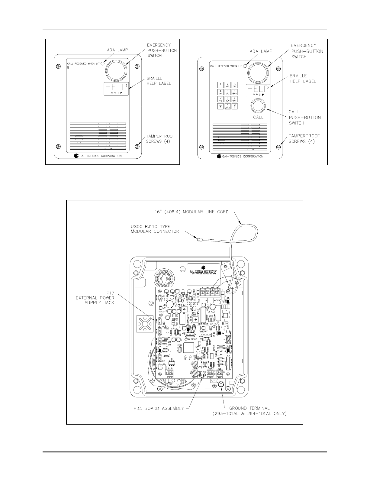
4. Pull the telephone line and power supply cord through the conduit.
5. Connect the power supply 4-pin connector to the P17 header jack on the PCBA.
6. Connect the telephone’s modular plug to a USOC RJ11 or CA11A (Canada) modular jack.
N
OTE: A modular jack may be mounted inside the telephone. Connecting the telephone line directly
to TB1 is acceptable.
7. Perform the initial programming of the phone. Refer to the Programming section on page 15.
8. Make hardware configuration changes, if necessary. Refer to page 12 for more information. Verify
the phone is operating properly by calling to and from another phone.
9. Adjust the speaker levels if necessary. See the Audio Level Adjustments section on page 14 for
details.
10. Complete the installation by attaching the front panel assembly to the rear enclosure using the four
tamper-res i stant screws .
\\s_eng\gtcproddocs \standard ioms - current release\42004 instr. manuals\42004-378c.doc
08/06
Page 9
Pub. 42004-378C
XTERNALLY POWERED ADA-COMPLIANT EMERGENCY PHONES PAGE 8 of 28
E
Figure 6. Model 293-101AL
Figure 7. Model 294-101AL
Figure 8. Model 293-101, 293-101AL, and 294-101AL Component Locations
\\s_eng\gtcproddocs \standard ioms - current release\42004 instr. manuals\42004-378c.doc
08/06
Page 10

Pub. 42004-378C
XTERNALLY POWERED ADA-COMPLIANT EMERGENCY PHONES PAGE 9 of 28
E
Models 297-101 and 298-101
Figure 9. Model 297-101
Figure 10. Model 298-101
Stanchion or Flush-mount Applications
1. When mounting in a GAI-Tronics Model 234 Series Stanchion or for flush-mount installations, the
supplied back box must be used to mount the Model 297-101 or 298-101 Telephone. Mount the back
box to the structure using the appropriate hardware. Refer to Figure 11 cutout dimensions.
2. If mounted outdoors, the installation of a telephone line suppressor (customer-supplied) on the
telephone line is recommended.
3. Remove the tapered plug from the top or bottom cable entry hole in the back box, and pull the
telephone line and power supply cord through.
4. Connect the power supply 4-pin connector to the P17 header jack on the PCBA.
5. Connect the telephone’s modular plug to a USOC RJ11 or CA11A (Canada) modular connector or (if
applicable) the telephone line suppressor. Refer to Figure 8 for the Model 297-101 and 298-101
component locations. Telephone line connections directly to TB1 are acceptable.
6. Perform the initial programming of the phone. Refer to the Programming section on page 15.
7. Make hardware configuration changes, if necessary. Refer to page 12 for more information. Verify
the phone is operating properly by calling to and from another phone.
8. Adjust the speaker levels if necessary. Refer to the Audio Level Adjustments section on page 14.
9. Attach the telephone’s front panel to the mounting flanges of the back box using the six supplied
#10-32 tamper-resistant screws and washers.
\\s_eng\gtcproddocs \standard ioms - current release\42004 instr. manuals\42004-378c.doc
08/06
Page 11

Pub. 42004-378C
XTERNALLY POWERED ADA-COMPLIANT EMERGENCY PHONES PAGE 10 of 28
E
Figure 11. Model 297-101 and 298-101 Mounting Details
\\s_eng\gtcproddocs \standard ioms - current release\42004 instr. manuals\42004-378c.doc
08/06
Page 12

Pub. 42004-378C
XTERNALLY POWERED ADA-COMPLIANT EMERGENCY PHONES PAGE 11 of 28
E
Figure 12. Model 297-101 and 298-101 Component Locations
(shown with connection to optional GAI-Tronics 530FB/531A Beacon)
Connecting a Beacon
Figure 12 above shows a typical connection detail of the GAI-Tronics 530FB/531A Beacon (sold
separately).
\\s_eng\gtcproddocs \standard ioms - current release\42004 instr. manuals\42004-378c.doc
08/06
Page 13

Pub. 42004-378C
XTERNALLY POWERED ADA-COMPLIANT EMERGENCY PHONES PAGE 12 of 28
E
Setup
Hardware Configuration
The hardware options are explained in the following sections and the necessary jumper settings are
identified to enable or disable each option. We recommend reading the following sections, recording the
desired parameters and then making the necessary changes. The User Settings column in the Hardwa re
Settings Table on page 23 is provided for you to record your settings. The following options are
control led by specific hardware configurat io ns. S e e Figure 1 3 for the jumper lo c atio ns .
Auto-answer Configura tion
Factory Setting: Auto-answer feature enabled
The Auto-answer feature enables or disables the automatic answering of an incoming call. When the
Auto-answer feature is enabled, the phone automatically answers the call. When this feature is disabled,
the emergency telephone’s call button must be pressed to answer the call.
Enable: Insert the J14 jumper on pins 2 and 3.
Disable: Insert the J14 jumper on pins 1 and 2 (Do not use this setting except under the direction of
GAI-Tronics personnel.)
OTE: The Auto-answer feature must be enabled during remote programming.
N
Polarity Configuration
Factory Setting: Non-polarity sensitiv e
This telephone can be configured to be polarity or non-polarity sensitive. When using the non-polarized
setting, the telephone operates with the telephone line’s positive terminal connected to either the tip or the
ring. When using the polarized setting, the telephone only operates with the telephone line’s positive
terminal connected to the tip. Use the Polarity Sensitive setting to allow a line voltage reversal disconnect
signal to disconnect the call.
Non-polarity Sensitive: Insert the J6 jumper on pins 2 and 3.
Polarity Sensitive: Insert the J6 jumper on pins 1 and 2.
Password Enable/Disable Configuration
Factory Setting: Ena b led
This telephone can be configured to enable or disable the password protection for programming. This can
be useful when initially programming the telephones. Please see the Programming section of this manual.
Password Enabled: Insert a jumper on pins 2 and 3 of J9.
Password Disabled: Insert a jumper on pins 1 and 2 of J9.
\\s_eng\gtcproddocs \standard ioms - current release\42004 instr. manuals\42004-378c.doc
08/06
Page 14

Pub. 42004-378C
XTERNALLY POWERED ADA-COMPLIANT EMERGENCY PHONES PAGE 13 of 28
E
Auxiliary Output
Each telephone includes one isolated solid state output capable of switching a maximum of 48 V dc, 125
mA or 28 V
ac, 80
RMS
mA. TB2 (OUT1) on the emergency phone PCBA provides the connections for
RMS
the auxiliary output. Refer to Figure 13 for the location of TB2.
The auxiliary output allows peripheral equipment, such as beacons, video cameras, and alarm generators,
to be activated when the E
MERGENCY push button is pressed. The relay re mains e nergized for the
duration of th e e mer gency c all.
In many applications, the auxiliary output is used to operate a GAI-Tronics Model 530FB/531A Beacon
(sold separately). For connection details, please refer to the Model 530FB/531A installation bulletin
included with the beacon. Information is also available at www.gai-tronics.com
.
Figure 13. Emergency Phone PCBA
\\s_eng\gtcproddocs \standard ioms - current release\42004 instr. manuals\42004-378c.doc
08/06
Page 15

Pub. 42004-378C
XTERNALLY POWERED ADA-COMPLIANT EMERGENCY PHONES PAGE 14 of 28
E
Audio Level Adjustments
Speaker Volume Adjustments
The speaker volume and microphone sensitivity are factory set to nominal levels that are acceptable for
most installations. However, some installations may require adjustments for the speaker and microphone.
Both the speaker and microphone adjustments are made using potentiometers on the emergency phone
PCBA. R106 is the speaker volume adjustment, and R88 is the microphone sensitivity adjustment.
Please refer to Figure 13 for the potentiometer locations.
Special care must be given to adjusting the speaker volume and microphone level. If one or both of the
levels are set too high, acoustic feedback (howling) can occur. If acoustic feedback occurs, we
recommend returning both potentiometers to the nominal factory settings and beginning the adjustment
again from this point.
Additionally, the acoustical characteristics of the emergency phones are different both when the front
panel is removed from the enclosure and when the front panel is tightly mounted in the enclosure. After
making an y volu me adjustments, we recomme nd mou nting the front panel to the e nclos ure and again
testing the phone.
\\s_eng\gtcproddocs \standard ioms - current release\42004 instr. manuals\42004-378c.doc
08/06
Page 16

Pub. 42004-378C
XTERNALLY POWERED ADA-COMPLIANT EMERGENCY PHONES PAGE 15 of 28
E
Programming
The telephone can be programmed remotely from a telephone, or locally at the telephone. To program
the Model 294-101AL and Model 298-101 locally, the front panel keypad can be used. However, to
program the 293-101, 293-101AL, and 297-101 models locally, a Model 51035-011 Keypad must be
connected to J13 on the telephone PCBA using the Model 51504-048 Keypad Cable Assembly. Refer to
Figure 8. See the Local Programming section on page 16.
For remote programming, a touch-tone (DTMF) telephone connected to a separate central office (CO) or
private branch exchange (PBX) line is required. Use a handset phone for remote programming the phone.
If a speakerphone is used, background noise can lead to incorrect settings. Do not use a cell phone. See
the Remote Programming section below.
Remote Programming
The programming mode is accessed by dialing a four-digit programming password. Should it become
necessary to bypass the password protection feature, see the Password Disabled Programming section on
page 16.
Password Enabled Programming
1. Enable the pass w ord prot ection featur e—insert the J9 jumper on pins 2 and 3.
2. Enable the auto-answer feature—insert the J14 jumper on pins 2 and 3.
3. Using a touch-tone telephone, call the emergency telephone. (Do not use a cell phone.) The
emergency telephone automatically answers the call and generates a splash tone followed by a
success tone (single beep).
4. Dial the four-digit p ass word. I f the password has not bee n altere d, dial 2468 (factory setting).
Otherwise, dial the preprogrammed user password. A success tone (single beep) is generated to
indicate the programming mode has been accessed.
NOTES:
• The telephone automatically times-out if 20 seconds elapse between digit entries, or if an invalid
password is enter ed.
• If DTMF digits have not been dialed within three seconds of the call initiation, the telephone
remains off-hook and the programming mode is terminated.
• If the success tone is not generated, the telephone has failed to recognize the password.
Therefore, the telephone must then be programmed with the password disabled. See the
Password Disabled Programming section on page 16.
5. If the success tone has been generated, begin entering the desired user-programmable parameters.
See the Programming Sequences section on page 18. A success tone (single beep) is generated each
time a new parameter is accepted. An error tone (two beeps) is generated to indicate an error. If an
error tone is generated, verify the programming sequence, and enter the sequence again.
6. Terminate the programming by placing the touch-tone telephone on-hook.
\\s_eng\gtcproddocs \standard ioms - current release\42004 instr. manuals\42004-378c.doc
08/06
Page 17

Pub. 42004-378C
XTERNALLY POWERED ADA-COMPLIANT EMERGENCY PHONES PAGE 16 of 28
E
Password Disabled Program ming
1. Disable the password protection feature—insert the J9 jumper on pins 1 and 2.
2. Enable the auto-answer feature—insert the J14 jumper on pins 2 and 3.
3. Using the touch-tone telephone, call the emergency telephone. The emergency telephone
automatically answers the call and generates a splash tone followed by a success tone (single beep).
4. Begin entering the desired programmable parameters. See the Programming Sequences section on
page 18. A success tone (single beep) is generated each time a new parameter is accepted. An error
tone (two beeps) is generated to indicate an error. If an error tone is generated, verify the
programming seque nce, and enter the sequence again.
OTE: The telephone automatically times-out if 20 seconds elapse between digit entries.
N
5. Terminate the programming by placing the touch-tone telephone on-hook.
Local Programming
For Models 293-101, 293-101AL, and 297-101, the procedure is as follows:
1. Connect keypad to connector J13. See F i gur e 8 and Figure 12 for details. Contact GAI-Troni c s
Field Service Department for details.
2. Tempor a r ily mo ve th e E
MERGENCY push-button switch harness from connector J7 to the CALL
pus h- button c onnector J1.
3. Disable the password protection f eatur e—insert the J9 jumper on pins 2 and 1.
4. Press the E
press 1 and #
MERGENCY push button. A dial tone is broadcast over the speaker. Simultaneously
on the keypad. The telephone generates a splash tone followed by a success tone.
5. Enter the desired programmable parameters. See the Programming Sequences section below.
A success tone (single tone [DTMF #]) tone is generated each time a new parameter is accepted. An
error tone (double beep) is generated to indicate an error. If an error tone is generated, verify the
programming sequence is correct, and enter the sequence again.
OTES:
N
• The telephone is off-hook during local programming. Therefore, programming should be
completed quickly to avoid any off-hook timeouts controlled by the CO or PBX.
• The telephone automatically times out if 20 seconds elapse between digit entries.
6. Terminate the programming by pressing the E
MERGENCY push button.
7. Disconnect the keypad from connector J13.
8. Return the E
MERGENCY push-button switch to connector J7.
9. Enable the pass w ord prot ection featur e—insert the J9 jumper on pins 3 and 2.
\\s_eng\gtcproddocs \standard ioms - current release\42004 instr. manuals\42004-378c.doc
08/06
Page 18

Pub. 42004-378C
XTERNALLY POWERED ADA-COMPLIANT EMERGENCY PHONES PAGE 17 of 28
E
For Models 294-101AL, and 298-101, the procedure is as follows:
1. Disable the password protection f eatur e—insert the J9 jumper on pins 2 and 1.
2. Press the C
ALL push button. A dial tone is broadcast over the speaker. Simultaneously press 1 and #
on the phone keypad. The telephone generates a splash tone followed by a success tone.
3. Enter the desired programmable parameters. See the Programming Sequences section below.
A success tone (single tone [DTMF #]) tone is generated each time a new parameter is accepted. An
error tone (double beep) is generated to indicate an error. If an error tone is generated, verify the
programming sequence is correct, and enter the sequence again.
OTES:
N
• The telephone is off-hook during local programming. Therefore, programming should be
completed quickly to avoid any off-hook timeouts controlled by the CO or PBX.
• The telephone automatically times out if 20 seconds elapse between digit entries.
4. Terminate the programming by pressing the C
ALL push button.
5. Enable the pass w ord prot ection featur e—insert the J9 jumper on pins 3 and 2.
\\s_eng\gtcproddocs \standard ioms - current release\42004 instr. manuals\42004-378c.doc
08/06
Page 19

Pub. 42004-378C
XTERNALLY POWERED ADA-COMPLIANT EMERGENCY PHONES PAGE 18 of 28
E
Programming Sequences
The programming information on the following pages explains the
programming options. The telephone is shipped from the factory
with a set of default parameters that are listed in the Programming
Table on page 23. A User Settings section has been provided in
th e Pr o g rammi ng Table f o r t he user to record the selected
Pr ogramming Ke y
D = digit 0-9, *, or #
N = digit 0-9
L = 0 - Disable, 1 - Enable
T = 0-350 ms, 1-50 ms, 2-25 ms
programming parameters.
It is recommended that the user read the sections that follow, record the desired parameters in the User
Settings section of the Programming Table, and then complete the programming using the instructions
fro m e i ther the Re mote Programming or t he Local Pr ogra mming section.
Dialing Optio ns
The emergency telephones can be configured for either auto-dialing or ring-down operation. Select the
dialing option that fits your application. The dialing options are explained in detail in the following
sections.
Auto-dialing
The emergency push button can be programmed to call three unique telephone numbers. The unique
telephone numbers include a primary telephone number and two backup, or roll over, numbers. In the
event an emergency call cannot connect to the primary telephone number (i.e., a busy signal or no
answer), the emergency phone will automatically dial the first backup, or roll over, number. Again, in the
event an emergency call cannot connect to first back-up telephone number, the emergency phone will
automatically dial the second backup, or roll over, number. This sequence will continue until the
emergency call is answered, or the sequence is repeated three times for a total of 12 call attempts.
For the rollover feature to function properly, all three auto-dial memories must be programmed with valid
telephone numbers. The three auto-dial numbers can be the same or any combination of phone numbers.
If the phone is programmed with only one or two auto-dial numbers, the rollover operation will not
function and the numbers will only be dialed one time.
If an emergency phone is connected to a PBX, PABX, KSU, etc., telephone system, the emergency phone
can be programmed to access outside CO lines. Typically access to a CO line requires adding a digit (e.g.
9) to the auto-dial number. Also, a “pause” may be required in the auto-dial number. The pause typically
is required to wait for secondary (CO line) dial tone. See the example in the Emergency Button Auto-dial
Number 1 in the table below.
In addition to the pause, the emergency telephone has a programmable Primary Dial Tone Delay and
Secondary Dial Tone Delay. Both delays determine the amount of time the emergency phone will wait
before dialing the stored telephone number. The Secondary Dial Tone Delay can only be used if a “9” is
dialed to gain access to a CO line.
\\s_eng\gtcproddocs \standard ioms - current release\42004 instr. manuals\42004-378c.doc
08/06
Page 20

Pub. 42004-378C
XTERNALLY POWERED ADA-COMPLIANT EMERGENCY PHONES PAGE 19 of 28
E
Ring-down Operation
Ring-down operation enables the telephone to go off-hook when the EMERGENCY push button is pressed.
The ring-down system must detect loop current and ring-down to the appropriate telephone.
Feature
Emergency
Button Auto-dial
Number 1
Emergency
Button Auto-dial
Number 2
Emergency
Button Auto-dial
Number 3
Key
Sequence
Description
DD ... *1 Assigns a telephone number to the auto-dial memory 1. DD ...
repr esents th e telephone number, wh ich can be up to 20 digits in
length.
For acces s to an out side line, a pa u s e may be requir ed in the
telephone number to wait for secondary dial tone. The #
repr esents a paus e in the telephone number.
Examples:
To assi gn the police em ergency number 911
button, enter
911*1.
to the auto-dial
To assi gn 9 1 1 wh en a “9” is required to gain a ccess to a CO
line, enter 9*#911*1.
To store * or # as part of the auto-dial number, (such as for
speed di aling ), en ter these digits twice in succession.
DD ... *2 Same as Emergency Button Auto-dial Number 1 except the
sequence ends in *2 instead of *1.
DD ... *3 Same as Emergency Button Auto-dial Number 1 except the
sequence ends in *3 instead of *1.
Default
*123456
789*0#
None
None
Call Button
Auto-dial
Prim ary Dial
Tone Delay
Secondary Dial
Tone Delay
Ring-down
Operation
DD ... *4 Same as Emergency Button Auto-dial Number 1 except the
sequence ends in *4 instead of *1.
# 1 0 N N The dial tone delay is the amount of time the unit waits for a
dial to ne b efore auto - dialing t he telephone number. (00
[infinite]; 01-15 seconds)
1 0 0 5.
# 1 1 N N
Example: To wait five seconds for a dial tone, enter #
This feature is only used if you must dial 9 to access a n ou tside
line. It determines the amount of time (00-15 seconds) the
telephone waits for a second dial tone. The first programming
step indicated you m ust progr a m 9*# and the numbe r you want
the auto-dial to access. This programming parameter allows
you to choose the amount of time the telephone waits after
encountering # before dialing the auto-dial n um ber.
Example: To wait ten secon d s for the second dial tone, enter
1 1 1 0.
#
*1
This option clears the telephone number to prevent auto-dialing
when th e bu tton is pr ess ed . Once the but ton is press ed , the ringdown system must det ect loop current and ring-down to the
appropr iate tele phon e.
None
00
(Infinite)
00 (0
seconds)
None
\\s_eng\gtcproddocs \standard ioms - current release\42004 instr. manuals\42004-378c.doc
08/06
Page 21

Pub. 42004-378C
XTERNALLY POWERED ADA-COMPLIANT EMERGENCY PHONES PAGE 20 of 28
E
Password
The P assword Prot ection feat ure a l lows you to chan ge th e four - digit pa ssword required to remotely
program the emergency telephone. Each telephone is password protected to maintain the integrity of
programmed information and should not be disabled.
The password is required to enter the programming mode when programming the telephone from a
remote lo c atio n. The p rogrammi ng pa ssword hardware configu ration must be enabl e d when
programming w ith the p ass word. To enab le the Passwor d Prot e ction fea tur e, insert the J9 jumper on pins
2 and 3. Complete the key sequence to change the four-digit password.
Feature
Password
Protection
Key
Sequence
Description
# 1 4 N N N N A four-digit password must be supplied to remotely program
the telephon e. If you ch ange the password an d cannot ent er
Default
2468
pr ogram m ing mode, s e e t he Pas sword D isabled Programming
section.
Example: To program the pa s s word 1234, enter #
1 4 1 2 3 4.
Silent Monito ring Feature
When the Silent Monitoring feature is enabled, individuals near the telephone will not be able to hear the
person who is monitoring the area.
Feature
Silent
Monitoring
Key
Sequence Description
# 1 6 L
Enabling the Silent Monitoring feature allows a person to call the
emergency telephone and monitor the area around the telephone
with the emergency telephone’s speaker muted.
To enable the Silent Monitoring feature, L=1.
To disable the Silent Monitoring feature, L=0.
Default
0
(Disabled)
Off-Hook R inging
The emergency phone can generate a ringing signal from the speaker when the phone is called. As a
factory default, this feature is disabled.
Feature
Ringing
Key
Sequence Description
# 2 2 L
Enabling the Off-Hook Ringing feature allows a person to call the
phone an d have the ph on e functi on as a n or mal teleph one. The
phone will ring after the splash tone is heard in the receiver if
remot e programming is not com menced within 7 secon d s of the
splas h to ne .
To ena ble the ringin g feature ( en able spla sh t one and ring ing), L=1.
To disable th e r i nging feat ure ( only splash tone on t he phone), L=0
OTE: Only Model 294AL-101 and 298-101 Phones can be
N
answer ed when they are ringin g by pressin g the Call but ton.
Default
0
(Disabled)
\\s_eng\gtcproddocs \standard ioms - current release\42004 instr. manuals\42004-378c.doc
08/06
Page 22

Pub. 42004-378C
XTERNALLY POWERED ADA-COMPLIANT EMERGENCY PHONES PAGE 21 of 28
E
Disconnec t Options
Sev eral options are availabl e for dis connecting a c all. An y comb inat ion of di sconnect options ma y be
used. Select the method that best suits the application, and follow the appropriate programming
directions.
Feature
Emergency
Push-button
Disconnect
Option
Call Time-out
Disconnect
Option
Key
Sequence Description
# 1 7 L
EMERGENCY button cannot be used to disconnect a call for 1 0
The
seconds after initially pressing the push button. However, the
emergency push bu tton can be used to disconnect calls after th e tensecond push button lockout period elapses when L=1. To preven t
EMERGENCY push button from disc onnec ting the ca ll, set L=0.
the
Example: To enable the
enter #
1 7 1. To disable the EMERGENCY push button
discon nect, ent er #
EMERGENCY push button disconnect,
1 7 0.
# 1 2 N N This feature programs the maximum length of a call if no other
discon nect features are u s ed . Th e va lid entri es are 1-99,
representing 1 minute increments and 0 representing 4.5 hours
(infinite). The call duration timer begins when the emergency
telephone goes off-hook. The emergency telephone automatically
discon nects aft er the progr ammed tim e- ou t period elapses.
The user can immediately press the
EMERGENCY button to
reconnect the autodial number. This feature helps prevent nonemergency calls from tying up emergency lines for long lengths of
time.
Example: To make the maximum call length two minutes, enter
2 0 2.
# 1
Default
1 (Enabled)
10 (10
minutes)
Dial Tone
Disconnect
Option
# 1 9 L
WARNING
Use this option on ly i f no other di s connect op tions are a vail able.
If this option is enabled, the telephone automatically terminates a
call if i t d etects a dial tone continuously for 1 0 s econds, such as if
the called part y h an g s up. To en able the di al tone disconnect, L=1.
To disable the dial tone disconnect, L=0.
Example: To enable the dial tone disconnect, enter #
disa bl e the dial tone disconn ect, ent er #
1 9 0.
1 9 1. To
0
(Disabled)
\\s_eng\gtcproddocs \standard ioms - current release\42004 instr. manuals\42004-378c.doc
08/06
Page 23

Pub. 42004-378C
XTERNALLY POWERED ADA-COMPLIANT EMERGENCY PHONES PAGE 22 of 28
E
Ameri cans with Di sabilit ies Act (A DA) Progra mming
The ADA fea tures pro vide th e fo l low ing benefits :
• C
ALL RECEIVED WHEN LIT indication - This lamp provides indication to hearing-impaired
individua ls that the emergency call has been a nswered.
• The Location Identification Code - This feature enables security personnel to quickly and easily
locate an individual in trouble.
• DTMF Call Disconnect - Enables the security operator to disconnect the call by pressing ##.
Feature
Key
Sequence
Description
ADA Options # 1 8 L This opt ion enabl es these features: call received i ndicator
lamp activation, location identification code dialing, and the
DTMF disconnect featur e.
To enable the ADA opti ons, set L=1. To disa ble the ADA
options, set L=0.
Location
Identification
ID Setup
# 1 3 L N N N This opt ion enabl es and stor es the three- d igit location
identification ID number. To enable the ID feature, set L=1.
To disable th e I D fe ature, L=0. Enter t he thre e-digi t locatio n
identification code in the sequence N N N.
For Example: To enable the location ID feature and store
the three-di gi t ID code 357, enter # 1 3 1 3 5 7. To disable
the location ID feature, enter # 1 3 0 0 0 0.
OTE: The ADA options must also be enabled.
N
Default
1 (Enabled)
No default
setting. The
user must
complete this
step t o have the
identification
code
transmitted.
\\s_eng\gtcproddocs \standard ioms - current release\42004 instr. manuals\42004-378c.doc
08/06
Page 24

Pub. 42004-378C
XTERNALLY POWERED ADA-COMPLIANT EMERGENCY PHONES PAGE 23 of 28
E
Hardware Settings Table
Default Settings User Settings
Function Setting Jumper/Position Setting Jumper/Position
Auto-answer Enabled J14/3 & 2
Pa ssword Protection Enabled J9/ 3 & 2
Line Polarity Non-polarized J6/3 & 2
Programming Table
Function Key Sequence Default
Settings
Auto-dial Programming
User Settings
Emergency Button Auto-dial Number 1 DD*1 *123456789*0#
Emergency Button Auto-dial Number 2 DD*2 None
Emergency Button Auto-dial Number 3 DD*3 None
Call Butto n Au to-d ial Nu mber DD*4 None
Primary Dial Tone Delay #10NN Infinite
Secondary Line Dial Tone Delay #11NN 0 (zero) seconds
Ring-down Operation *1 None
Password Programming
Pa ssword Protection #14 NNNN 2468
Disconnect Programming
Emergency Push-button Disconnect #17L 01 (enabled)
Call Time-out Disconnect #12NN 10 minutes
Dial Tone Disconnect #19L 0 (disabled)
Other Programming Features
Silent Monitoring #16L 0 (disabled)
Ringing #22L 0 (disabled)
ADA Programming
ADA Options Enable #18L #181
Identification Code Entry #13LNNN None
Table Key
D = digit 0-9, *, or # N = digit 0-9
L = 0-Disable, 1-Enable T = 0-350 ms, 1-50 ms, 2-25 ms
\\s_eng\gtcproddocs \standard ioms - current release\42004 instr. manuals\42004-378c.doc
08/06
Page 25

Pub. 42004-378C
XTERNALLY POWERED ADA-COMPLIANT EMERGENCY PHONES PAGE 24 of 28
E
Maintenance
If your GAI-Tronics Phone requires service, contact your GAI-Tronics Regional Service Center for a
return authorization number (RA#). Equipment should be shipped prepaid to GAI-Tronics with a return
authorization number and a purchase order number. If the equipment is under warranty, repairs will be
made without charge. Please include a written explanation of all defects to assist our technicians in their
tr oubleshootin g e f for ts.
Call 800-492-1212 inside the USA or 610-777-1374 outside the USA for help identifying the Regional
Service Center closest to y o u.
\\s_eng\gtcproddocs \standard ioms - current release\42004 instr. manuals\42004-378c.doc
08/06
Page 26

Pub. 42004-378C
XTERNALLY POWERED ADA-COMPLIANT EMERGENCY PHONES PAGE 25 of 28
E
Specification s
Auto-dial digit limit..................................................................................................................... 24 digits
Electrical
Audio output ................................................... Voice - 90 dB SPL @ 1 meter independent of loop current
1 kHz tone - 90 dB SPL @ 1 meter independent of loop current
Input .............................................................................................................................. 12 V dc, 200 mA
Phone line requirements ....................................................................... Loop start, central office (CO), or
Analog station port (PBX, PABX, or KSU)
Minimum loop current.................................................................................... 24 mA with external power
40 mA without external power
Auxiliary output (isolated solid state switch)............................................................... 48 V dc @ 125 mA
28 V
Signaling.....................................................................................................................DTMF 100 ms tone
Memory ................................................................................................................ Non-volatile EEPROM
Mechanical
Operating temperature range............................................................................................ -20º C to +60º C
Relative humidity................................................................................................ to 95%, no condensation
PCBA (printed circuit board assembly)...........................................................................Conformal coated
ac @ 80 mA
RMS
RMS
Model 293-101
Enclosure construction ....................Valox (high impact, glass-reinforced polyester) painted safety yellow
Dimensions ........................................................... 9.5 H × 8 W × 4 D inches (241.3 × 203.2 × 101.6 mm)
Weight .......................................................................................................................................... 4.0 lbs.
Models 293-101AL and 294-101AL
Enclosure construction..................................................................... Cast aluminum painted safety yellow
(Model 294-101AL only) Braille dial pad...............................................................Chrome-plated zinc
Dimensions ........................................................... 9.5 H × 8 W × 4 D inches (241.3 × 203.2 × 101.6 mm)
Weight
Model 293-101AL................................................................................................................... 7.8 lbs.
Model 294-101AL................................................................................................................... 8.5 lbs.
Model 297-101 and 298-101
Construction
Panel................................................................................................ 14-gauge, brushed stainless steel
Back box..................................................... 16-gauge cold-rolled steel with black polyurethane finish
(Model 298-101 only) Braille dial pad...................................................................Chrome-plated zinc
Dimensions
Panel................................................................................. 12.0 H × 10.0 W inches (304.8 × 254 mm)
Back box (depth from mounting surface).......................................................... 2.38 inches (60.5 mm)
Panel Cutout .............................................................. 10.1 H × 8.43 W inches (255.57 × 214.12 mm )
Weight
Model 297-101........................................................................................................................ 6.5 lbs.
Model 298-101........................................................................................................................ 7.2 lbs.
\\s_eng\gtcproddocs \standard ioms - current release\42004 instr. manuals\42004-378c.doc
08/06
Page 27

Pub. 42004-378C
XTERNALLY POWERED ADA-COMPLIANT EMERGENCY PHONES PAGE 26 of 28
E
Approvals
Safety of Information Technology Equipment....................................................................UL/CSA 60950
Enclosures for Electrical Equipment.................................................................................UL 50, Type 3R
47 CFR Part 68
Certification Number....................................................................................US: ADGTE03B294AL103X
Ringer Equivalence Number ...............................................................................................AC-REN: 0.3B
Network connection (USOC)...........................................................................................................RJ11C
IC Information (Canada)
IC Certification Number............................................................................................. 882B-AUXSMART
Ringer Equivalence Number ...............................................................................................................0.2A
Connection method……………………………………………………………………………….. CA11A
Replacement Parts
Part No. Description
233-001
Model 233-001 Tamper-Resistant
293-
101
293-
101AL
Screwdriver
12562-105
Emergency PCBA Replacement Kit
(Standard)
51035-005 PCBA, Keypad, metallic
28299-007
Tamperproof Screws
(Flus h- mo u nt mode ls )
28229-004 Tamperproof Screws, 1-1/8 inch
12520-006
Push Button Replacement Kit
(1.5-inch, red)
12520-007
Push Button Replacement Kit
(1.0-inch, black)
40419-005 Plug-in Power Supply
12521-001 Microphone Replacement Kit
12522-003 Speaker Replacement Kit
294-
101AL
297-
101
298-
101
51035-011
Keypad, plastic
(als o used f or local programming)
61504-048
Keypad Cable Assembly
(als o used f or local programming)
\\s_eng\gtcproddocs \standard ioms - current release\42004 instr. manuals\42004-378c.doc
08/06
Page 28

Pub. 42004-378C
XTERNALLY POWERED ADA-COMPLIANT EMERGENCY PHONES PAGE 27 of 28
E
User Instructions (USA)
This equ ipment com plies with Part 68 of th e F C C r u les and the r equiremen ts adopted b y th e ACTA. On this
equip ment is a label that cont ains, among other informati on, a product identifier in th e format
US:AAAEQ##TXXXX. If requested , th i s num ber must be provided t o th e telephone company.
A plug an d jack used to connect this equipmen t to the premises wiring and telep hone networ k must comp ly with the
applicable FCC Part 68 rules and requirements adopted by the ACTA. A compliant telephone cord and modular
plug is provided with this product. It is designed to be connected to a compatible modular jack that is also
compliant. See installation instructions for details.
The REN is u sed to determ ine the number of devices that may be con nected to a teleph on e line. Excessi ve RENs on
the telephon e line may resul t in the devices not rin ging in response to an incoming cal l. In most but n ot al l areas, th e
sum of th e RE Ns should not ex ceed five (5. 0 ) . To be cer tain of th e n um ber of devices that ma y be con nected to a
line, as determined by the total RENs, contact the local telephone company. For products approved after July 23,
2001, the REN for this product is part of the product identifier that has the format US:AAAEQ##TXXXX. The
digits represented by ## are the REN without a decimal point (e.g., 03 is an REN of 0.3). For earlier products, the
REN is separately shown on the label.
If this equipment [GAI-Tronics telephone] causes harm to the telephone network, the telephone company will notify
you in advance that temporary discontinuance of service may be required. But if advance notice isn’t practical, the
telephone company will notify the customer as soon as possible. Also, you will be advised of your right to file a
complaint with the FCC if you believe it is necessary.
The telephon e com p any may mak e changes in it s fa cilities, equipmen t , operati ons, or proced u res that could affect
the operation of the equipment. If this happens the telephone company will provide advance notice in order for you
to make necessary modifications to maintain uninterrupted service.
If tr oubl e is experienced with this eq ui pm en t [GAI-Tronics telephon e] , for repair or warranty informati on , please
contact GAI-Tronics Corporation at 800-492-1212 or www.gai-tronics.com. If the equipment is causing harm to the
telephone net wor k , the tel ephone company may reques t that you disconnect the equ ip ment until the problem is
resolved.
Connection to party line service is subject to state tariffs. Contact the state public utility commission, public service
commission or corporation commission for information.
User Instructions (Canada) CP-01, Issue 8, Part I: Section 14.1
NOTICE: The Industry Canada la bel identifies certified equ ipment. Th is certification means that th e eq uipment
meets certain t elecommun ications network protecti ve, opera tional an d safety req u irements as prescr ibed in the
appr opriate T erm inal Equipment Tech n ical Requirements document (s). Th e Department d oes not guarantee the
equip ment will operate to the user's satisfaction. Befor e installing thi s eq u ip ment, users shoul d en sure that it is
permissible to be connected to the facilities of the local telecommunications company. The equipment must also be
inst alled using an accepta bl e method of connect ion. The custom er shoul d be a ware that compliance with the abo ve
conditions may not prevent degradation of service in some situations. Repairs to certified equipment should be
coordinated by a representative designated by the supplier. Any repairs or alterations made by the user to this
equipment, or equipment malfunctions, may give the telecommunications company cause to request the user to
discon nect the equipmen t. Users shoul d ensure for their own prot ection that the electrica l ground conn ections of the
power u tility, telephon e lines and in ternal metallic wat er pipe system, if present, are con nected together. Th is
precaution may be particularly important in rural areas.
CAUTION
Users should not attempt to make such connections themselves, but should contact the appropriate electric
inspection authority, or electrician, as appropriate.
CP-01, Issue 8, Part I: Section 14.2
NOTICE: The Ringer Equivalenc e Number (RE N ) assigned t o ea ch terminal device pr ovides an indicati on of the
maximum number of terminals allowed to be connected to a telephone interface. The termination on an interface
may consist of any combination of devices subject only to the requirement that the sum of the Ringer Equivalence
Number s of a ll the device s d oes not exceed 5.
\\s_eng\gtcproddocs \standard ioms - current release\42004 instr. manuals\42004-378c.doc
08/06
Page 29

Pub. 42004-378C
XTERNALLY POWERED ADA-COMPLIANT EMERGENCY PHONES PAGE 28 of 28
E
Underwr i ters Lab oratories I nc. ( “UL”) has not tested the performance or reliab ility of the emergency
aspects of this produ c t. UL has only t es ted f or fire, shock and/or casualty hazards as outl ined i n UL’s
Standard for Safety UL60950-1. UL Certification does not cover the performance or reliability of the
emergency aspects of this product. UL MAKES NO REPRESENTATIONS, WARRANTIES OR
CERTIFICATIONS WHATS OEVER REGARDING THE PE RFORMANCE OR RELIABILITY OF
ANY EMERGENCY RELATED FUNCTIONS OF THIS PRODUCT.
Confidentiality Notice
This manua l is pr ov ided s olel y as an installation, operati on, a nd maintenance guid e and contai ns sensiti ve
business and technical information that is confidential and proprietary to GAI-Tronics. GAI-Tronics
retains all intellectual property and other rights in or to the information contained herein, and such
information may only be used in connection with the operation of your GAI-Tronics product or system.
This manua l may not be dis closed in any form, i n whol e or in part, directly or indirect ly, t o any t hird party.
\\s_eng\gtcproddocs \standard ioms - current release\42004 instr. manuals\42004-378c.doc
08/06
Page 30

Warranty
Equipment. GAI-Tronics warrants for a period of one (1) year from the date of shipment, that any
GAI-Tronics equipment supplied hereunder shall be free of defects in material and workmanship, shall
comply with the then-current product specifications and product literature, and if applicable, shall be fit
for the purpose specified in the agreed-upon quotation or proposal document. If (a) Seller’s goods prove
to be defective in workmanship and/or material under normal and proper usage, or unfit for the purpose
specified and agreed upon, and (b) Buyer’s claim is made within the warranty period set forth above,
Buyer may return such goods to GAI-Tronics’ nearest depot repair facility, freight prepaid, at which time
they will be repaired or replaced, at Seller’s option, without charge to Buyer. Repair or replacement shall
be Buyer’s sole and exclusive remedy. The warranty period on any repaired or replacement equipment
shall be the greater of the ninety (90) day repair warranty or one (1) year from the date the original
equipment was shipped. In no event shall GAI-Tronics warranty obligations with respect to equipment
exceed 100% of the total cost of the equipment supplied hereunder. Buyer may also be entitled to the
manufacturer’s warranty on any third-party goods supplied by GAI-Tronics hereunder. The applicability
of any such third-party warranty will be determined by GAI-Tronics.
Services. Any services GAI-Tronics provides hereunder, whether directly or through subcontractors,
shall be performed in accordance with the standard of care with which such services are normally
provided in the industry. If the services fail to meet the applicable industry standard, GAI-Tronics will
re-perform such services at no cost to buyer to correct said deficiency to Company's satisfaction provided
any and all issues are identified prior to the demobilization of the Contractor’s personnel from the work
site. Re-performance of services shall be Buyer’s sole and exclusive remedy, and in no event shall GAITronics warranty obligations with respect to services exceed 100% of the total cost of the services
provided hereunder.
Warranty Periods. Every claim by Buyer alleging a defect in the goods and/or services provided
hereunder shall be deemed waived unless such claim is made in writing within the applicable warranty
periods as set forth above. Provided, however, that if the defect complained of is latent and not
discoverable within the above warranty periods, every claim arising on account of such latent defect shall
be deemed waived unless it is made in writing within a reasonable time after such latent defect is or
should have been discovered by Buyer.
Limitations / Exclusions. The warranties herein shall not apply to, and GAI-Tronics shall not be
responsible for, any damage to the goods or failure of the services supplied hereunder, to the extent
caused by Buyer’s neglect, failure to follow operational and maintenance procedures provided with the
equipment, or the use of technicians not specifically authorized by GAI-Tronics to maintain or service the
equipment. THE WARRANTIES AND REMEDIES CONTAINED HEREIN ARE IN LIEU OF AND
EXCLUDE ALL OTHER WARRANTIES AND REMEDIES, WHETHER EXPRESS OR IMPLIED BY
OPERATION OF LAW OR OTHERWISE, INCLUDING ANY WARRANTIES OF
MERCHANTABILITY OR FITNESS FOR A PARTICULAR PURPOSE.
Return Policy
If the equipment requires service, contact your Regional Service Center for a return authorization number
(RA#). Equipment should be shipped prepaid to GAI-Tronics with a return authorization number and a
purchase order number. If the equipment is under warranty, repairs or a replacement will be made in
accordance with the warranty policy set forth above. Please include a written explanation of all defects to
assist our technicians in their troubleshooting efforts.
Call 800-492-1212 (inside the USA) or 610-777-1374 (outside the USA) for help identifying the
Regional Service Center closest to you.
(Rev. 10/06)
 Loading...