

Page 1

Pub. 42004-338K
G A I - T R O N I C S®
A H U B B E L L C O M P A N Y
Rugged Analog Auto-Dial Telephones
T A B L E O F C O N T E N T S
GAI-TRONICS 3030 KUTZTOWN RD. READING, PA 19605 USA
610-777-1374 ◼ 800-492-1212 ◼ Fax: 610-796-5954
VISIT WWW.GAI-TRONICS.COM FOR PRODUCT LITERATURE AND MANUALS
Confidentiality Notice .....................................................................................................................1
General Information .......................................................................................................................1
Operation .........................................................................................................................................1
Installation ......................................................................................................................................2
Safety Guidelines ..................................................................................................................................... 2
Security Hardware .................................................................................................................................. 2
Conduit Installation Details ................................................................................................................... 2
Model 227-001 ......................................................................................................................................... 4
Model 247-001 ......................................................................................................................................... 6
Model 257-001 ......................................................................................................................................... 8
Model 277-001 ....................................................................................................................................... 10
Flush-Mount Installation ..................................................................................................................... 10
Surface-Mount Installation using a 236-00x Series or Model 238-001 Enclosure ............................. 11
Models 277-002BH and 277-002BHAC ............................................................................................... 12
Flush-Mount Installation ..................................................................................................................... 12
Surface-Mount Installation using the No. 238-003 Enclosure ............................................................ 13
Programming Auto-Dial Numbers ...................................................................................................... 14
Ringdown Operation ............................................................................................................................ 14
Maintenance ..................................................................................................................................15
Service .................................................................................................................................................... 15
Preventive Maintenance for Models 277-001/-002BH/-002BHAC ................................................... 15
Cleaning .............................................................................................................................................. 15
Prevention ........................................................................................................................................... 15
Volume Control Jumper Setting .......................................................................................................... 16
Auxiliary Output ................................................................................................................................... 16
Replacement Parts and Accessories .............................................................................................17
Specifications ................................................................................................................................18
Electrical (Typical) ................................................................................................................................ 18
Environmental ....................................................................................................................................... 18
Mechanical ............................................................................................................................................. 19
Approvals .......................................................................................................................................20
Page 2

Pub. 42004-338K
G A I - T R O N I CS®
A H U B B E L L C O M P A N Y
Rugged Analog Auto-Dial Telephones
GAI-TRONICS 3030 KUTZTOWN RD. READING, PA 19605 USA
610-777-1374 ◼ 800-492-1212 ◼ Fax: 610-796-5954
VISIT WWW.GAI-TRONICS.COM FOR PRODUCT LITERATURE AND MANUALS
Confidentiality Notice
This manual is provided solely as an installation, operation, and maintenance guide and contains sensitive
business and technical information that is confidential and proprietary to GAI-Tronics. GAI-Tronics
retains all intellectual property and other rights in or to the information contained herein, and such
information may only be used in connection with the operation of your GAI-Tronics product or system.
This manual may not be disclosed in any form, in whole or in part, directly or indirectly, to any third
party.
General Information
GAI-Tronics Rugged Auto-Dial Telephones are ideally suited for conditions that are too harsh for a
standard telephone. When the handset is removed from the cradle, a preprogrammed number of up to 31
digits is automatically dialed. The telephones are fully line-powered and do not require internal batteries.
This manual applies to the following telephones:
• Model 227-001 Public Access Auto-dial Telephone
• Model 247-001 Indoor Industrial Auto-dial Telephone
• Model 257-001 Weatherproof Industrial Auto-dial Telephone
• Model 277-001 Flush-Mount Auto-dial Telephone
• Models 277-002BH and 277-002BHAC Flush-Mount Behavioral Health Telephone
Operation
To auto-dial the stored telephone number:
1. Lift the handset. After approximately 1 second, the preprogrammed number is dialed automatically.
2. The handset receiver volume is adjustable using the handset pressbar or the volume control
pushbutton located on the front of the telephone. The volume increases with each button press in six
steps. Pressing the volume control a seventh time will reset the volume to the original level. When
the handset is returned to its cradle, the receiver volume is returned to the initial volume setting. This
behavior can be changed by the volume control jumper setting (see the Volume Control Jumper
Setting section).
3. To redial, place the handset on hook and wait approximately 3 seconds. Lift the handset and the
preprogrammed number is redialed.
4. Place the handset back on-hook after completion of the call.
Page 3

Pub. 42004-338K
Rugged Analog Auto-Dial Telephones Page 2 of 21
P:\Standard IOMs - Current Release\42004 Instr. Manuals\42004-338K.docx
10/19
Installation
ATTENTION
—Installation should be performed by qualified personnel and only in
accordance with the National Electrical Code or applicable local codes.
Safety Guidelines
When installing any GAI-Tronics telephone equipment, please adhere to the following guidelines to
ensure the safety of all personnel:
• NEVER install telephone wiring during a lightning storm.
• Install a UL Listed lightning arrestor on any telephone installed where the telephone or telephone
cable is at risk of being exposed to lightning strikes. The lightning arrestor must be installed as close
as possible to maximize the protection. It must not be installed within the enclosure supplied with the
telephone. Please consult our Service Center at 800-492-1212 for further information.
• Do not install telephone jacks in wet locations unless the jack is specifically designed for wet
locations.
• Do not touch uninsulated telephone wires or terminals unless the telephone line has been
disconnected at the network interface.
Security Hardware
Models 227-001, 277-001, 277-002BH, and 277-002BHAC are vandal resistant. The front panel of each
of these models is attached to its enclosure with security screws. A GAI-Tronics Model 233-001 Security
Screwdriver or Torx T-25 security head tip (sold separately) is necessary to install the security screws.
Model 247-001 and 257-001 Telephones’ front panels are attached with standard Phillips head screws.
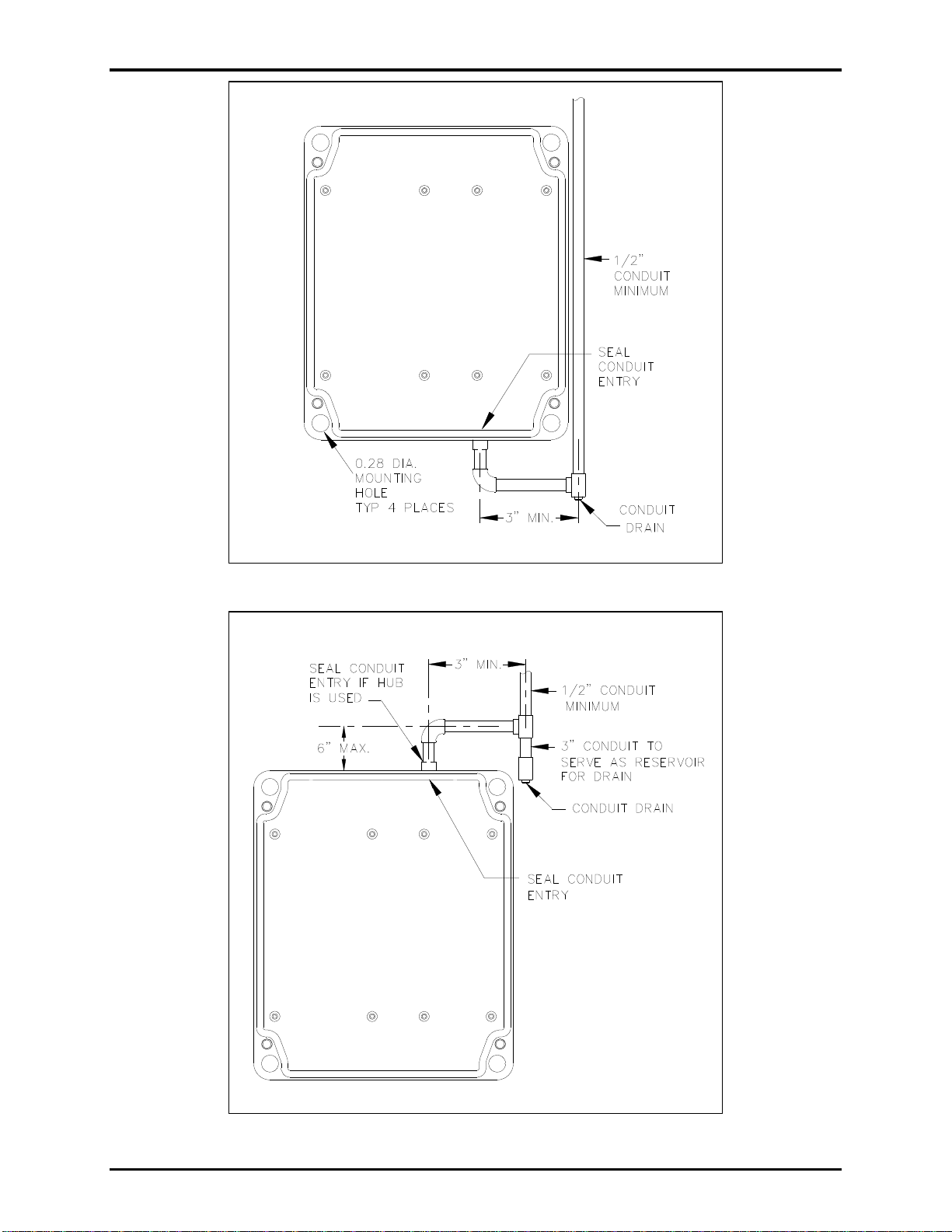
Conduit Installation Details (Applicable to Models 247-001 and 257-001)
GAI-Tronics recommends installing telephone lines in conduit to protect against accidental damage and
vandalism. The following measures help prevent moisture from entering the enclosure (see Figure 1 and
Figure 2):
• Conduit should enter the enclosure from the bottom whenever possible.
• Sealed fittings should be installed at all cable entry points.
• Silicone sealant or equivalent should be applied around and inside all conduit entries to prevent
moisture ingress.
Page 4
Pub. 42004-338K
Rugged Analog Auto-Dial Telephones Page 3 of 21
Figure 1. Bottom entry conduit installation details (RECOMMENDED for non-metallic enclosures)
Figure 2. Top entry conduit installation details (NOT RECOMMENDED)
P:\Standard IOMs - Current Release\42004 Instr. Manuals\42004-338K.docx
10/19
Page 5
Pub. 42004-338K
Rugged Analog Auto-Dial Telephones Page 4 of 21
Model 227-001
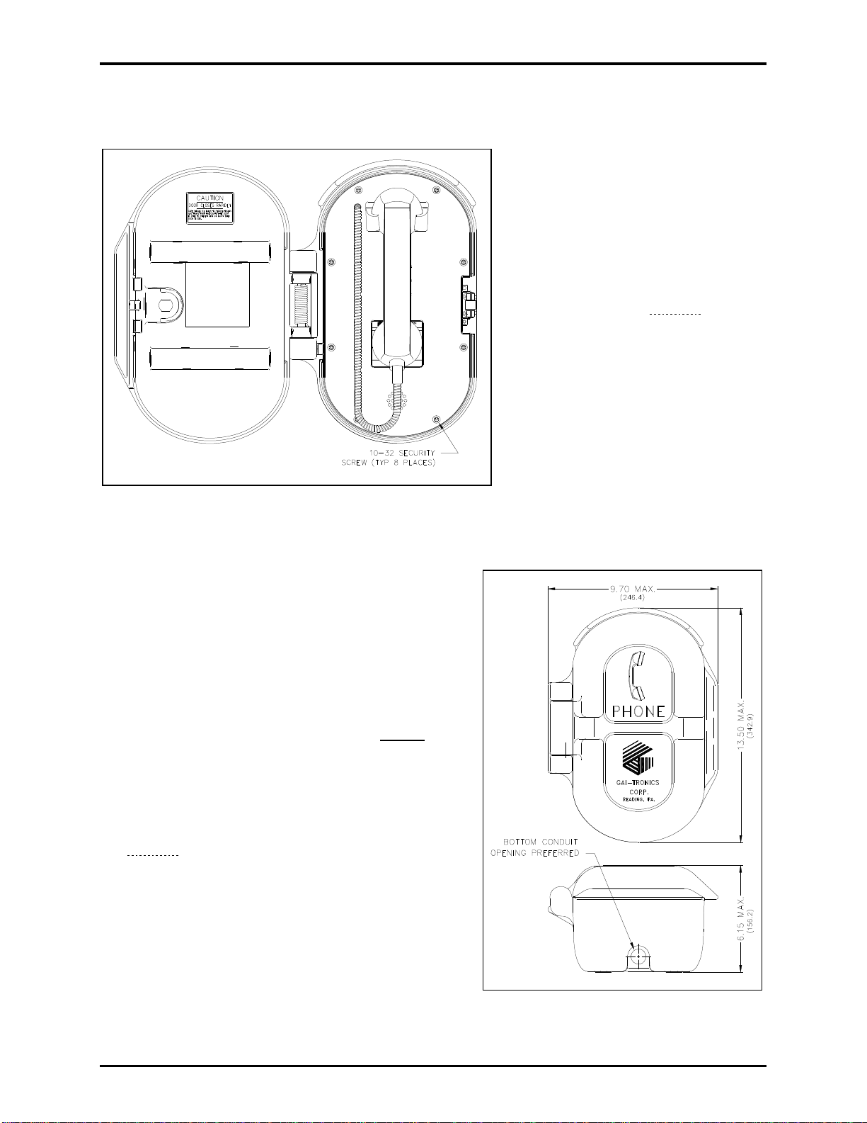
The mounting and wiring instructions for the Model 227-001 Public Auto-Dial Telephone are as follows:
1. Remove the eight security screws
from the front panel. Remove the
front panel and set aside.
OTE: There is a 7-foot half-
N
modular telephone cord
attached to the PCBA in
the rear.
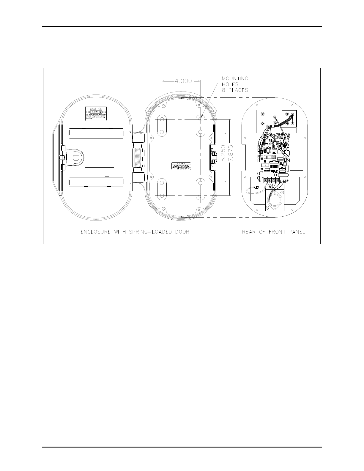
2. Determine which hole pattern to use
for mounting (see Figure 5).
• There are eight mounting holes
in the back of the enclosure in
two 4-hole patterns.
• Use the 7.875 × 4.00-inch hole
pattern for mounting to a wall
(outside pattern).
• Use the 5.25 × 4.00-inch hole
pattern when using the Model
232-001 Pole Mounting Kit
(inside pattern).
in the unused holes.
Figure 3. Model 227-001 Public Access Telephone with
spring loaded door in the open position
3. Insert the four (provided) hole plugs
4. Position the enclosure on the mounting surface and
secure it with four fasteners.
• The holes in the telephone enclosure accept 3/8-
inch screws or bolts.
• The Model 232-001 Pole Mounting Kit includes
four 3/8-16 × 1-inch shoulder bolts with Teflon
seal washers.
N
OTE: Use only the round head, hexagon head, or pan
head screws that are provided. Do not use
screws designed to be countersunk for
mounting the enclosure.
5. Install a conduit fitting in one of the ½-inch NPT
conduit entrances provided at both the top and bottom
of the unit and insert the conduit into the fitting (see
Figure 4).
The bottom entry is preferred.
6. Plug the unused access hole using the provided 3/8-
inch Allen drive plug.
OTE: Use silicone sealant or equivalent around and
N
inside all conduit entries.
7. Outdoor Installations: install a (customer-supplied)
telephone line suppressor on the telephone line.
Figure 4. Model 227-001 Outline
8. Pull the telephone line through the conduit and into the enclosure.
P:\Standard IOMs - Current Release\42004 Instr. Manuals\42004-338K.docx
10/19
Page 6
Pub. 42004-338K
Rugged Analog Auto-Dial Telephones Page 5 of 21
9. Connect the telephone’s modular cord to the incoming subscriber line with the appropriate connector.
10. Verify operation by calling to and from another telephone.
11. Replace the front panel assembly and tighten the eight front panel screws.
Figure 5. Model 227-001 Outline and Mounting Drawing
P:\Standard IOMs - Current Release\42004 Instr. Manuals\42004-338K.docx
10/19
Page 7
Pub. 42004-338K
Rugged Analog Auto-Dial Telephones Page 6 of 21
Model 247-001
1. Remove the four front panel screws using a standard Phillips screwdriver.
2. Remove the front panel assembly and set it aside.
3. Disconnect the 7-foot half-modular telephone cord from the PCBA terminal strip, if connected (see
Figure 7).
4. Conduit Installations: See the Conduit Installation Details section.
If using the gland bushing provided with the unit: Drill a 0.688-inch diameter hole at either drill spot
on the bottom of the rear enclosure.
5. Push the free end of the telephone
cord through the gland bushing
using needle-nose pliers.
Allow 8–10 inches of telephone
cord to extend past the bushing.
6. Tighten the bushing around the
cord.
7. Feed the free end of the telephone
cord through the hole in the
enclosure.
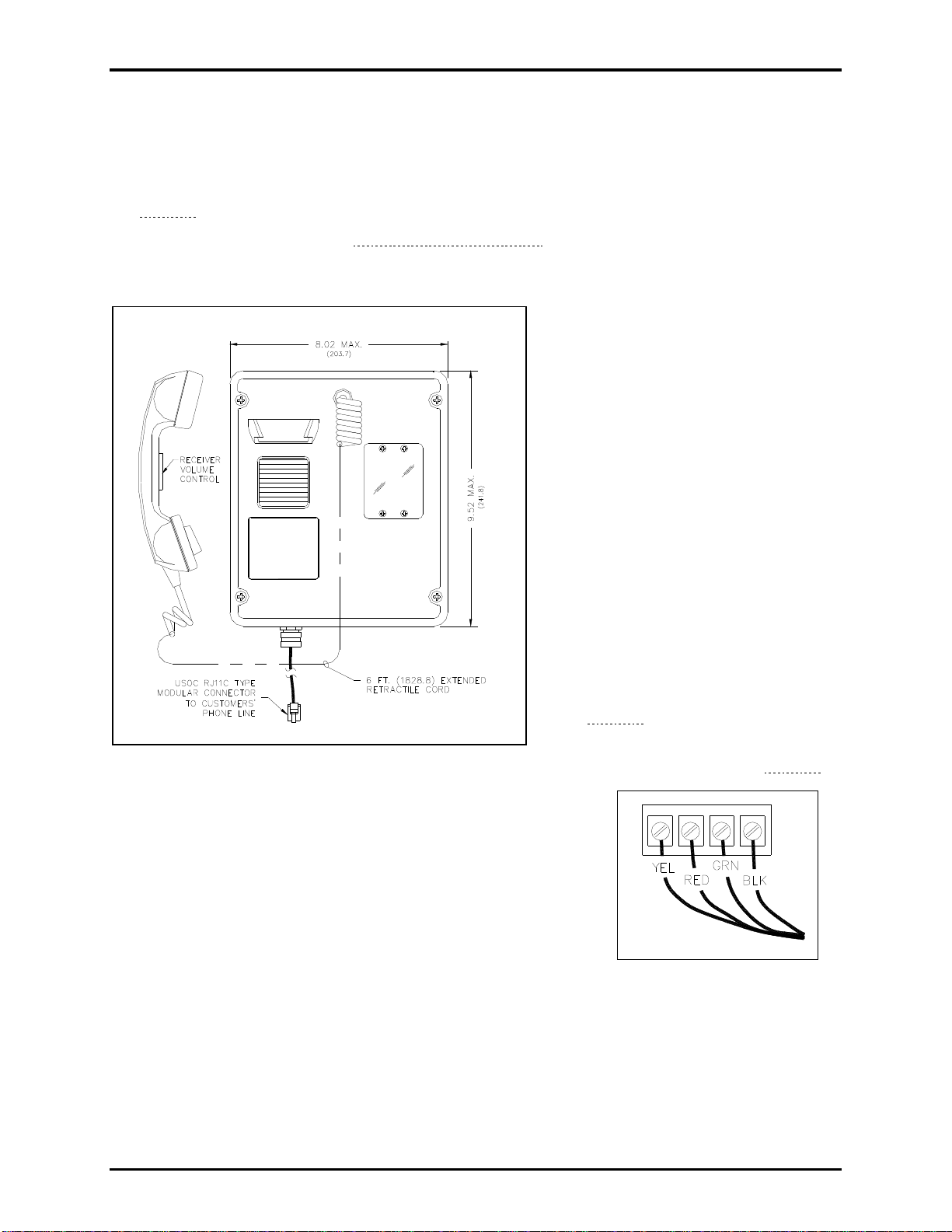
Figure 6. Model 247-001 Outline Drawing
11. Replace the front panel assembly and secure it with the four
front panel screws.
12. Connect the telephone cord’s modular connector to the
incoming subscriber line using the appropriate mating
connector.
13. Check for proper telephone operation by calling to and from
another telephone.
8. Secure the bushing in the hole with
the supplied locknut using a 7/8inch wrench and channel lock pliers.
9. Mount the enclosure to the wall with
four 1/4-20 machine screws with
nuts and washers or with four #14
wood screws of the appropriate
length for the mounting surface (see
Figure 8).
10. Connect the telephone cord to the
PCBA terminal strip (see Figure 7).
Figure 7. PCBA Connection
P:\Standard IOMs - Current Release\42004 Instr. Manuals\42004-338K.docx
10/19
Page 8

Pub. 42004-338K
Rugged Analog Auto-Dial Telephones Page 7 of 21
Figure 8. Model 247-001 Mounting Diagram
P:\Standard IOMs - Current Release\42004 Instr. Manuals\42004-338K.docx
10/19
Page 9

Pub. 42004-338K
Rugged Analog Auto-Dial Telephones Page 8 of 21
Model 257-001
1. Open the front door and remove the
four outermost screws from the midsection using a standard Phillips
screwdriver.
2. Pull the enclosure apart until
encountering a slight resistance on the
left side.
3. Open the front half of the enclosure to
the left until the length of the telephone
cord inside the enclosure can be
disconnected from the PCBA terminal
strip, if connected (see Figure 10).
4. Pull on the left side of the enclosure
until the hinge plugs pull loose to
separate the front and rear halves.
5. Set the front half of the enclosure
aside.
Figure 9. Model 257-001 Outline Drawing
6. Conduit Installations: See the Conduit Installation Details section.
If using the gland bushing provided with the unit: Drill a 0.688-inch diameter hole at either drill spot
on the bottom of the rear enclosure.
7. Push the free end of the telephone cord through the gland bushing using needle-nose pliers.
Allow 8–10 inches of telephone cord to extend past the bushing.
8. Tighten the bushing around the cord.
9. Feed the free end of the telephone cord through the hole in the enclosure.
10. Secure the bushing in the hole with the supplied locknut using a 7/8-inch wrench and channel locks to
tighten.
11. Mount the enclosure on the wall using four ¼-20 machine screws with nuts and washers or with four
#14 wood screws of the appropriate length for the mounting surface (see Figure 10).
12. Outdoor Installations: Install a (customer-supplied) telephone line suppressor on the telephone line.
13. Connect the telephone cord to the PCBA terminal strip (see Figure 7).
14. Close the front half of the enclosure and secure it by replacing the four outermost screws.
15. Connect the telephone’s modular cord to the incoming subscriber line with the appropriate mating
connector.
16. Verify operation by calling to and from another telephone.
P:\Standard IOMs - Current Release\42004 Instr. Manuals\42004-338K.docx
10/19
Page 10

Pub. 42004-338K
Rugged Analog Auto-Dial Telephones Page 9 of 21
Figure 10. Model 257-001 Mounting Detail
P:\Standard IOMs - Current Release\42004 Instr. Manuals\42004-338K.docx
10/19
Page 11

Pub. 42004-338K
Rugged Analog Auto-Dial Telephones Page 10 of 21
Model 277-001
Flush-Mount Installation
Use the supplied back box to mount the Model 277-001 Telephone in a Model 234 Series Communication
Station or for flush-mount installations
Figure 11. Model 277-001 Outline Drawing
1. Mount the back box to the structure using appropriate hardware (see Figure 12).
2. Outdoor installations: Install a (customer-supplied) telephone line surge suppressor on the telephone
line.
3. Remove a tapered plug from a cable-entry hole in the back box and install the (customer-supplied)
telephone line and cable fitting.
4. Recommendation—use silicone sealant or equivalent around and inside all conduit entries.
5. Connect the modular connector of the 7-foot supplied telephone cord to the incoming subscriber line
or the telephone line suppressor (if applicable) using the appropriate mating connector.
6. Attach telephone’s front panel to the mounting flanges of the back box using the six supplied #10
security screws and the six black flat washers.
A Model 233-001 Security Screwdriver (sold separately) is required to install the security screws.
P:\Standard IOMs - Current Release\42004 Instr. Manuals\42004-338K.docx
10/19
Page 12

Pub. 42004-338K
Rugged Analog Auto-Dial Telephones Page 11 of 21
Figure 12. Model 277-001 Back Box Mounting Detail
Surface-Mount Installation using a 236 -00x Series or Model 238-001 En closure
OTE: The back box included with the Model 277-001 Telephone is not required for use with a Model
N
236 Series or Model 238-001 Surface-Mount Enclosure and must be removed.
1. Drill or punch conduit entries. (The Model 238-001 already includes a rear-access hole with gasket.)
WARNING
—To prevent accidentally damaging equipment, drill all holes before
mounting the telephone.
2. Outdoor Installations: Install a (customer-supplied) telephone line suppressor on the telephone line.
3. Connect the telephone’s modular plug to the incoming subscriber line or the telephone line suppressor
(if applicable) using the appropriate mating connector.
4. Attach the telephone’s front panel to the mounting flanges of the Model 236 Series or 238-001
Surface-Mount Enclosure using the six supplied #10-32 security screws and six black flat washers.
A Model 233-001 Security Screwdriver (sold separately) is required to install the security screws.
5. Torque the cover screws to 10–12 in⋅lb.
P:\Standard IOMs - Current Release\42004 Instr. Manuals\42004-338K.docx
10/19
Page 13

Pub. 42004-338K
Rugged Analog Auto-Dial Telephones Page 12 of 21
Models 277-002BH and 277-002BHAC
Flush-Mount Installation
N
OTE: See the cutout and support framing details for installation planning (see Figure 15).
1. Remove the four nuts from the back of the dust cover and remove it from the front panel (see Figure
13 and Figure 14).
Figure 13. Models 277-002BH/-002BHAC Outline Drawing
Figure 14. Models 277-002BH/-002BHAC Dust Cover Detail
P:\Standard IOMs - Current Release\42004 Instr. Manuals\42004-338K.docx
10/19
Page 14

Pub. 42004-338K
Rugged Analog Auto-Dial Telephones Page 13 of 21
2. Feed the telephone line through either of the cable entry holes in the dust cover (see Figure 14).
3. Connect the telephone’s modular cord to the incoming subscriber line with the appropriate connector.
OTE: Telephone line connections directly to TB1 are acceptable.
N
4. Verify operation by calling to and from another telephone.
5. Place the dust cover back onto the telephone and secure it using the four nuts removed in step one.
6. Attach the front panel assembly to the mounting surface using the six supplied #10-32 thread-cutting
security screws (see Figure 15).
Figure 15. Cutout Detail and Framing Support for Models 277-002BH/-002BHAC
Surface-Mount Installation using the No. 23 8-003 Enclosure
The Model 238-003 Enclosure includes rear and bottom access holes for cable entry. Use the rear access
hole(s) for a completely hidden installation or the bottom access hole(s) for conduit installation.
OTE: The dust cover included with the Model 277-002BH and 277-002BHAC Telephones is not
N
required for use with the Model 238-003 Surface-Mount Enclosure and must be removed.
1. Connect the telephone’s modular plug to the incoming subscriber line using the appropriate mating
connector.
2. Attach the telephone’s front panel to the mounting flanges of the No. 238-003 Surface-Mount
Enclosure using the six #10-32 security machine screws supplied with the surface mount enclosure kit
and the six black flat washers included with the telephone
OTE: Do not use the thread-cutting screws supplied with the telephone in the No 238-003
N
enclosure’s tapped holes. A Model 233-001 Security Screwdriver (sold separately) is
required for installing the security screws.
3. Torque the screws to 10–12 in∙lb.
P:\Standard IOMs - Current Release\42004 Instr. Manuals\42004-338K.docx
10/19
Page 15

Pub. 42004-338K
Rugged Analog Auto-Dial Telephones Page 14 of 21
Programming Auto-Dial Numbers
1. Remove the front panel assembly by following the appropriate instructions provided in this manual
for your phone.
2. Insert the supplied portable keypad and cable into J7 (see Figure 16).
3. The plug-in jumper on the connector header J2 should be installed between pins 2 and 3 (default).
4. Connect the telephone line cable from the telephone to an active telephone line.
5. Remove the handset from the cradle (off hook) and enter the desired telephone number into memory
using the keypad mounted on the back of the front panel assembly.
6. Once the number is entered, replace the handset in the cradle (on hook) and move the plug-in jumper
on J2 to pins one and two.
7. Test the auto-dial number by removing the handset from its cradle (off hook)–the telephone should
automatically dial the preprogrammed number.
8. Once the auto-dial number is verified, remove the keypad and cable and store in a safe location.
9. Reattach the front panel to the enclosure.
OTE: The programmed number remains in memory until it is reprogrammed. Disconnecting the
N
telephone line does not erase the programmed number. The number is stored in nonvolatile
electronic memory. Standby batteries are not required.
Ringdown Op eration
The plug-in jumper on the connector header J2 is factory installed between pins two and three. This
setting allows loop detection and dial tone when the handset is removed from its cradle. No programming
changes are necessary for ringdown operation.
Figure 16. Main PCBA Jumper Locations for Auto-dial Telephone
P:\Standard IOMs - Current Release\42004 Instr. Manuals\42004-338K.docx
10/19
Page 16

Pub. 42004-338K
Rugged Analog Auto-Dial Telephones Page 15 of 21
P:\Standard IOMs - Current Release\42004 Instr. Manuals\42004-338K.docx
10/19
Maintenance
Service
Contact a GAI-Tronics regional service center for an RA# (return authorization number) if the telephone
requires service. Equipment must be shipped prepaid to GAI-Tronics with a return authorization number
and a purchase order number. Repairs will be made without charge if the equipment is under warranty.
Please include a written explanation of all defects to assist our technicians in their troubleshooting efforts.
Call 800-492-1212 inside the USA or 610-777-1374 outside the USA for identification of the nearest
regional service center.
Preventive Maintenance for Models 277-001/-002BH/-002BHAC
Stainless steel does require maintenance to prevent corrosion from occurring. Different installation
locations may require more regular maintenance than others, depending on the environment and exposure
to airborne contaminants. The following maintenance steps should be performed on a regular basis or
when corrosion is first noticed on the Model 277-001 telephone.
Cleaning
• For general cleaning, wipe the surface with a cleanser or a cleanser and water mixture. Any cleanser
that is safe for glass is usually safe for stainless steel. Wipe dry.
• If corrosion or rusting is noticed, remove with a non-abrasive commercial cleanser and water. Rub
stained areas in the same direction as the existing grain. Stubborn stains may be removed with a
magnesium oxide, ammonia, and water paste. Wipe clean with water rinse and dry.
Prevention
Automotive wax provides the best results in preventing corrosion on stainless steel. Simply apply wax,
let dry to a haze, and buff to a shine with a clean dry cloth. This application should protect the telephone
surface for many months as it will allow natural reformation of the chromium oxide layer.
Do NOT use steel wool, sandpaper, mineral acids, bleaches, or chlorine cleansers on the stainless
surface.
Page 17

Pub. 42004-338K
Rugged Analog Auto-Dial Telephones Page 16 of 21
Volume Control Jumper Setting
The handset receiver volume control is factory set to default to its original setting (0 dB) when the
telephone is hung up. Move jumper J4 from positions 2 and 3 to positions 1 and 2
to save the current
volume control setting when hanging up the telephone (see Figure 17).
Auxiliary Output
Each telephone includes one isolated solid-state volt-free closure capable of switching a maximum of 48
V dc, 125 mA; or 28 V ac
for the auxiliary output (see Figure 17).
The auxiliary output allows peripheral equipment, such as beacons, video cameras, and alarm generators,
to be activated when the handset is off hook. The relay remains energized for the duration of the call.
, 80 mA
RMS
. TB2 (AUX OUT) on the main PCBA provides the connections
RMS
Figure 17. Location of TB2 on Main PCBA
P:\Standard IOMs - Current Release\42004 Instr. Manuals\42004-338K.docx
10/19
Page 18

Pub. 42004-338K
Rugged Analog Auto-Dial Telephones Page 17 of 21
P:\Standard IOMs - Current Release\42004 Instr. Manuals\42004-338K.docx
10/19
Replacement Parts and Accessories
Table 1. Replacement Parts
Part No.
Description
227-001
247-001
257-001
277-001
277-002BH
277-002BHAC
10111-104
Handset Assembly with 6-foot Hytrel®
Coiled Cord, Volume Control, and NoiseCanceling Mic, Black
10117-001
Handset Assembly with 15-inch Armored
Cord, Volume Control, and Noise-Canceling
Mic, Black
10117-003
Handset Assembly with 29-inch Armored
Cord, Volume Control, and Noise-Cancelling
Mic, Black
10113-030
Handset Assembly with 12-inch armored
cord
10113-020
Handset Assembly with 15-inch armored
cord
12512-001
Hookswitch/Cradle Kit
12512-002
Hookswitch/Cradle Kit
12516-001
Replacement Mounting Screw Kit (Phillips,
#10-32 machine screw, 10 pack)
12542-002
Replacement Mounting Screw Kit (Security,
#10-32 machine screw, 15 pack)
12542-003
Replacement Mounting Screw Kit (Security,
#10 thread cutting screw, 15 pack)
13707-004
Replacement Ringer Assembly
12513-006
Replacement Door Kit
69147-104
Replacement PCB Assembly
Page 19

Pub. 42004-338K
Rugged Analog Auto-Dial Telephones Page 18 of 21
P:\Standard IOMs - Current Release\42004 Instr. Manuals\42004-338K.docx
10/19
Table 2. Available Accessories
Part No.
Accessories
227-001
247-001
257-001
277-001
277-002BH
277-002BHAC
12565-009
Ring Relay Kit
12565-010
Ring Relay Kit
12573-001
Spring Door Kit
12576-117
Front Panel Replacement Kit
230-001
Pole Mounting Kit, Rugged Phone/RF
Callbox
231-001FS
Pole Mounting Kit for BH/FS Series
Telephones when installed in a No. 238003 Enclosure
231-002
Pole Mounting Kit for Model 247-001 and
for Model 277-001 when installed in a No.
238-001 Enclosure
232-001
Pole Mounting Kit (22x Series)
233-001
Security Screwdriver, Torx T-25 Tip
238-001
Surface-Mount Enclosure, Stainless Steel,
Standard
238-003
Surface-Mount Enclosure, Stainless Steel,
BH Telephones
Specifications
Electrical (Typical)
Auto-dialer ........................................ maximum 31 digits, with internal 12-button pad, field-programmable
Frequency response ............................................................................................................... 300 to 3,000 Hz
Inter-digit pause ................................................................................................................................... 100 ms
Minimum loop current ......................................................................................................................... 20 mA
Signaling tone (DTMF) ................................................................................................. 100 ms tone duration
Supervisory dc current ................................................................. minimum 20 mA dc; maximum 60 mA dc
Supervisory dc voltage ................................................................. 24 V dc to 60 V dc (not polarity sensitive)
Network interface ............................................................................................................................. loop start
Network signaling ................................................................................................................................ DTMF
Auxiliary output (isolated solid-state switch) .................................................................. 48 V dc @ 125 mA
28 V ac
RMS
@ 80 mA
RMS
Handset receiver volume gain .............................................................................. +18 dB in 3 dB increments
Environmental
Operating temperature ......................................................................... −40 ºF to +140 ºF (−40 ºC to +60 ºC)
Humidity ....................................................................................................................... 90% non-condensing
Page 20

Pub. 42004-338K
Rugged Analog Auto-Dial Telephones Page 19 of 21
P:\Standard IOMs - Current Release\42004 Instr. Manuals\42004-338K.docx
10/19
Mechanical
Model 227-001
Construction
Enclosure ........................................................ thick-walled cast aluminum with protective gray coating
Panel ......................................................................................................... 0.125-inch brushed aluminum
Finish ..................................................................................................................... gray polyurethane enamel
Handset/cord .......................................................................... G-style with armored cord and volume switch
Front panel ....................................................................................... 0.125-inch brushed anodized aluminum
Hookswitch ................................................................. chrome-plated zinc, stationary switching mechanism
Models 247-001 and 257-001
Enclosure .......................................................................................... high-impact, glass-reinforced polyester
Handset cord ........................ G-style handset/Hytrel® 6-foot extended length (standard) and volume switch
Connections............................................................................................ 6.5-foot (1.98 m) modular line cord
Dimensions, Outside
Model 247-001 ............................................................ 9.5 H × 8.0 W × 6.9 D in (242 × 204 × 174 mm)
Model 257-001 .......................................................... 13.2 H × 9.4 W × 7.4 D in (344 × 239 × 188 mm)
Mounting ........................................................................................................ four 0.280-inch diameter holes
Weight
Model 247-001 ................................................................................................................ 6.0 lb (2.70 kg)
Model 257-001 ................................................................................................................ 8.2 lb (3.72 kg)
Model 277-001
Enclosure construction: Front panel ......................... 14-gauge (0.075 inch) type 304 brushed stainless steel
Enclosure construction: Back box.......... 16-gauge (0.060 inch) cold-rolled steel with black polyester finish
Dimensions
Front panel .................................................................................. 12.00 H × 10.00 W in (305 × 254 mm)
Back box (overall) .............................................. 10.06 H × 8.43 W × 2.50 D in (256 × 214 × 63.5 mm)
Cutout for mounting back box ...................................................... 10.13 H × 7.63 W in (257 × 194 mm)
Weight ...................................................................................................................................... 6.5 lb (3.0 kg)
Handset/cord .......................................................................... G-style with armored cord and volume switch
Hookswitch ................................................................. chrome plated zinc; stationary switching mechanism
Models 277-002BH/-002BHAC
Enclosure Construction
Front panel ......................................................... 14-gauge (0.075-inch) type 304 brushed stainless steel
Back box ................................... 16-gauge (0.060-inch) cold-rolled steel with black polyurethane finish
Dimensions
Front panel ....................................................................................... 8.5 H × 7.5 W in (215 × 190.5 mm)
Back box (overall) .......................................... 7.62 H × 5.62 W × 2.37 D in (193.6 × 142.7 × 60.2 mm)
Cutout for flush mounting ........................................................ 7.75 H 5.75 W in (196.9 × 146.1 mm)
Weight ...................................................................................................................................... 5.0 lb (2.3 kg)
Handset/cord ......................................................................................................... G-style with armored cord
Page 21

Pub. 42004-338K
Rugged Analog Auto-Dial Telephones Page 20 of 21
P:\Standard IOMs - Current Release\42004 Instr. Manuals\42004-338K.docx
10/19
Approvals
Safety of Information Technology Equipment ................... UL 60950 and CAN/CSA-C22.2 NO. 60950-00
Enclosures for Electrical Equipment .................................................................. UL 50 TYPE 3R/NEMA 3R
FCC Information
FCC Registration Number ............................................................................... US: ADGTE10A-46048HAC
Ringer Equivalence Number (REN) ............................................................................................... 1.0A/1.3B
Network Connection (USOC) ................................................................................................................. RJ11
Meets hearing aid compatibility magnetic field intensity and volume control technical standards per FCC
Sections 68.316 and 68.317.
IC Information (Canada)
IC Certification Number ................................................................................................................. 82211754
Ringer Equivalence Number (REN) ............................................................................................... 1.0A/1.3B
Connecting Method ............................................................................................................................. CA11A
User Instructions (USA)
This equipment has been tested and found to comply with the limits for a Class A digital device, pursuant to part 15
of the FCC Rules. These limits are designed to provide reasonable protection against harmful interference when the
equipment is operated in a commercial environment. This equipment generates, uses, and can radiate radio
frequency energy and, if not installed and used in accordance with the instruction manual, may cause harmful
interference to radio communications. Operation of this equipment in a residential area is likely to cause harmful
interference in which case the user will be required to correct the interference at his own expense.
This equipment complies with Part 68 of the FCC rules. Located on the equipment is a label that contains, among
other information, the FCC registration number and REN (ringer equivalence number). If requested, this
information must be provided to the telephone company. The REN is used to determine the quantity of devices
which may be connected to the telephone line. Excessive REN’s on the telephone line may result in the devices not
ringing in response to an incoming call. In most, but not all areas, the sum of the REN’s should not exceed five
(5.0). To be certain of the number of devices that may be connected to the line, as determine by the total REN’s
contact the telephone company to determine the maximum REN for the calling area. This equipment cannot be used
on the telephone company-provided coin service. Connection to Party Line Service is subject to State Tariffs. If
this equipment causes harm to the telephone network, the telephone company will notify you in advance that
temporary discontinuance of service may be required. If advance notice isn’t practical, the telephone company will
notify the customer as soon as possible. Also, you will be advised of your right to file a complaint with the FCC if
you believe it is necessary. The telephone company may make changes in its facilities, equipment, operations, or
procedures that could affect the operation of the equipment. If this happens, the telephone company will provide
advance notice in order for you to make the necessary modifications in order to maintain uninterrupted service.
If trouble is experienced with this equipment, please contact:
GAI-Tronics Corporation
400 E. Wyomissing Ave.
Reading, PA 19540 USA
800-492-1212 or 610-777-1374
If the trouble is causing harm to the telephone network, the telephone company may request you to remove the
equipment from the network until the problem is resolved. This equipment uses the following USOC jacks: RJ11C.
It is recommended that the customer install an ac surge arrester in the ac outlet to which this device is connected.
This is to avoid damaging the equipment caused by local lightning strikes and other electrical surges. This
equipment is HAC (Hearing-Aid Compatible). The telephone Consumer Protection Act of 1991 makes it unlawful
for any person to use a computer or other electronic device, including fax machines, to send any message unless
such message clearly contains in a margin at the top or bottom of each transmitted page or on the first page of the
transmission, the date and time it is sent and an identification of the business or other entity, or other individual
sending the message, and the telephone number of the sending machine or such business, other entity, or individual.
(The telephone number provided may not be a 900 number or any other number for which charges exceed local or
long-distance transmission charges.)
Page 22

Pub. 42004-338K
Rugged Analog Auto-Dial Telephones Page 21 of 21
P:\Standard IOMs - Current Release\42004 Instr. Manuals\42004-338K.docx
10/19
User Instructions (Canada) CP-01, Issue 8, Part I: Section 14.1
NOTICE: The Industry Canada label identifies certified equipment. This certification means that the equipment
meets certain telecommunications network protective, operational, and safety requirements as
prescribed in the appropriate Terminal Equipment Technical Requirements document (s). The
Department does not guarantee the equipment will operate to the user's satisfaction. Before installing
this equipment, users should ensure that it is permissible to be connected to the facilities of the local
telecommunications company. The equipment must also be installed using an acceptable method of
connection. The customer should be aware that compliance with the above conditions may not prevent
degradation of service in some situations. Repairs to certified equipment should be coordinated by a
representative designated by the supplier. Any repairs or alterations made by the user to this
equipment, or equipment malfunctions, may give the telecommunications company cause to request the
user to disconnect the equipment. Users should ensure for their own protection that the electrical
ground connections of the power utility, telephone lines and internal metallic water pipe system, if
present, are connected together. This precaution may be particularly important in rural areas.
CAUTION
—Users should not attempt to make such connections themselves, but should contact
the appropriate electric inspection authority, or electrician, as appropriate.
CP-01, Issue 8, Part I: Section 14.2
NOTICE: The REN (Ringer Equivalence Number) assigned to each terminal device provides an indication of
the maximum number of terminals allowed to be connected to a telephone interface. The termination
on an interface may consist of any combination of devices subject only to the requirement that the sum
of the ringer equivalence numbers of all the devices does not exceed five.
Page 23

Warranty
Equipment. GAI-Tronics warrants for a period of one (1) year from the date of shipment, that any
GAI-Tronics equipment supplied hereunder shall be free of defects in material and workmanship, shall
comply with the then-current product specifications and product literature, and if applicable, shall be fit
for the purpose specified in the agreed-upon quotation or proposal document. If (a) Seller’s goods prove
to be defective in workmanship and/or material under normal and proper usage, or unfit for the purpose
specified and agreed upon, and (b) Buyer’s claim is made within the warranty period set forth above,
Buyer may return such goods to GAI-Tronics’ nearest depot repair facility, freight prepaid, at which time
they will be repaired or replaced, at Seller’s option, without charge to Buyer. Repair or replacement shall
be Buyer’s sole and exclusive remedy. The warranty period on any repaired or replacement equipment
shall be the greater of the ninety (90) day repair warranty or one (1) year from the date the original
equipment was shipped. In no event shall GAI-Tronics warranty obligations with respect to equipment
exceed 100% of the total cost of the equipment supplied hereunder. Buyer may also be entitled to the
manufacturer’s warranty on any third-party goods supplied by GAI-Tronics hereunder. The applicability
of any such third-party warranty will be determined by GAI-Tronics.
Services. Any services GAI-Tronics provides hereunder, whether directly or through subcontractors,
shall be performed in accordance with the standard of care with which such services are normally
provided in the industry. If the services fail to meet the applicable industry standard, GAI-Tronics will
re-perform such services at no cost to buyer to correct said deficiency to Company's satisfaction provided
any and all issues are identified prior to the demobilization of the Contractor’s personnel from the work
site. Re-performance of services shall be Buyer’s sole and exclusive remedy, and in no event shall GAITronics warranty obligations with respect to services exceed 100% of the total cost of the services
provided hereunder.
Warranty Periods. Every claim by Buyer alleging a defect in the goods and/or services provided
hereunder shall be deemed waived unless such claim is made in writing within the applicable warranty
periods as set forth above. Provided, however, that if the defect complained of is latent and not
discoverable within the above warranty periods, every claim arising on account of such latent defect shall
be deemed waived unless it is made in writing within a reasonable time after such latent defect is or
should have been discovered by Buyer.
Limitations / Exclusions. The warranties herein shall not apply to, and GAI-Tronics shall not be
responsible for, any damage to the goods or failure of the services supplied hereunder, to the extent
caused by Buyer’s neglect, failure to follow operational and maintenance procedures provided with the
equipment, or the use of technicians not specifically authorized by GAI-Tronics to maintain or service the
equipment. THE WARRANTIES AND REMEDIES CONTAINED HEREIN ARE IN LIEU OF AND
EXCLUDE ALL OTHER WARRANTIES AND REMEDIES, WHETHER EXPRESS OR IMPLIED BY
OPERATION OF LAW OR OTHERWISE, INCLUDING ANY WARRANTIES OF
MERCHANTABILITY OR FITNESS FOR A PARTICULAR PURPOSE.
Return Policy
If the equipment requires service, contact your Regional Service Center for a return authorization number
(RA#). Equipment should be shipped prepaid to GAI-Tronics with a return authorization number and a
purchase order number. If the equipment is under warranty, repairs or a replacement will be made in
accordance with the warranty policy set forth above. Please include a written explanation of all defects to
assist our technicians in their troubleshooting efforts.
Call 800-492-1212 (inside the USA) or 610-777-1374 (outside the USA) for help identifying the
Regional Service Center closest to you.
(Rev. 10/06)
 Loading...