

Page 1

Pub. 42004-178D
GAI-TRONICS® CORPORATION
A HUBBELL COMPANY
Model 263
Isolation B arrier Unit
Confidentiality Notice
This manua l is provide d sole ly as an operatio nal, installation, and ma inte nance guide and conta ins
sensitive business and t e chnical informatio n tha t is confidentia l and pr opri et ary to GAI- Tronics.
GAI-Tronics retains all intellectual property and other rights in or to the information contained herein,
and such information may only be used in connection with the operation of your GAI-Tronics product or
system. This manu al may not be dis clos e d in any form, in whole or in pa rt, direct ly or i ndir ectly, to a ny
third pa r ty.
General Information
GAI-Tronics Corporation offers intrinsically-safe (I.S.) telephones and isolation barrier units (IBU),
which conform to all pertinent requirements in the USA and Canada. For convenience, a telephone and
an IBU can be purchased together under a single model number: Model 261-001 for indoor use, and
Model 271-001 for outdoors.
However, for rack-mount configurations or special applications, the telephones and IBUs can be
purchased separately:
• Model 262-001 Indoor I.S. Phone
• Model 272-001 Outdoor I.S. Phone
• Model 263 Isolation Barrier Unit
The I.S. telephones are designed to be installed in all hazardous areas. The IBU or rack-mount card unit
is placed in a non-hazardous area up to one mile from the phone, limiting the energy levels going to the
hazardous area to conform to intrinsically-safe requirements.
The Model 263 Isolation Barrier Unit is constructed of durable glass-reinforced polyester, which is highly
resistant to chemicals and weather, and is rated Type 3R (rainproof).
GAI-Tronics Corporation P.O. Box 1060, Readi ng, PA 19607-1060 USA
610-777-1374 800-492-1212 Fax: 610-796-5954
ISIT WWW.GAI-TRONICS.COM FOR PRODUCT LITERATURE AND MANUALS
V
Page 2
Pub. 42004-178D
Model 263 Isolation Barrier Unit (IBU) Page: 2 of 13
Installation
Installa tion Guidelines
When installing any GAI-Tronics telephone equipment, please adhere to the following guidelines to
ensure the safety of all personnel:
• NEVER install telephone wiring during a lightning storm.
• Install a UL Listed lightning arrestor on any phone installed where the phone or phone cable is at
ris k of bei ng exposed to lig htning strikes . The l ight ning arr es tor must b e installed as cl ose t o the
phone as possible to maximize the protection. The lightning arrestor must not be installed within the
enclosure supplied with the phone.
• NEVER install telephone jacks in wet locations unless the jack is specifically designed for wet
locations.
• NEVER touch uninsulated telephone wires or terminals unless the telephone line has been
disconnected at the network interface.
• USE CAUTION when installing or modifying telephone lines.
• Install UL Listed telephone line suppressor (customer-supplied) on the telephone line.
• Use silicone sealant or equivalent around and inside all conduit entries
Installa tion of the IB U
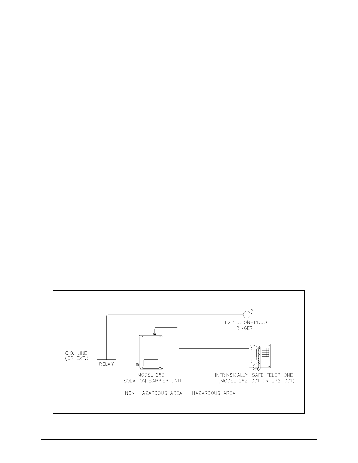
The Model 263 Isolation Barrier Unit provides an intrinsically-safe circuit when connected in accordance
with GAI-Tronics Pub. 42004-380, Control Drawing 73242. It must be installed in a non-hazardous
location. See Figure 1 for a typical installation.
The Model 263 Isolation Barrier Unit interior includes a power switch selector, a ring pitch adjustment,
and f our troubleshooting LEDs. The I BU hou sing is compose d of two modular suba ssembl ies, the fr ont
panel and the rear enclosure assembly, for easy installation and wiring.
Figure 1. Typic al in trin sic ally-safe install ation
\\s_eng\gtc proddoc s \st andard iom s - current release\42004 instr. manuals \ 42004-178d. doc
03/06
Page 3
Pub. 42004-178D
Model 263 Isolation Barrier Unit (IBU) Page: 3 of 13
Wiring Requirements
Design Lim its
In order to be intrinsically safe , energy and energy storage must be constrained to “safe” levels in
hazardou s area ap para tus. Wiring i nherentl y has capacitance formed by a dielect ric material between tw o
conductors. A buildup of this capa c itance can for m a surge of elect ricity, a dangerous situatio n in a
hazardou s area.
Intrinsically-safe telephones require cabling that will limit the amount of capacitance formed. The
limitat ion on cable length was set b y Underwriter’ s La boratory (UL ) based on test results. This “ worst
case” cable available was found to have a capacitance of 60 picofarads/foot. Therefore, UL set the cable
limitation at one mile, the length at which this worst-case cable capacitance level was still within
acceptable bounds. Cable types with less capacitance have been specified to allow connection distances
over one mile.
For example: GAI-Tronics Model 60059-001 and 60021-301 cables allow connection distances of up to
1.5 miles.
Shiel ded Cable
Where multiple I.S. telephone wires are routed together, shielded cable should be used. The use of
shielded cable prevents cross-talk from occurring between multiple I.S. telephone circuits. The shield
must be grounded to an I.S. ground and connected only at the IBU.
Wiring G uidelin es/Contr ol Drawi ng
The Model 263 provides an intrinsically-safe circuit when installed in accordance with GAI-Tronics Pub.
42004-380, Control Drawing 73242. In addition, the NEC and the CEC provide additional installation
details that are recommended for safe installation.
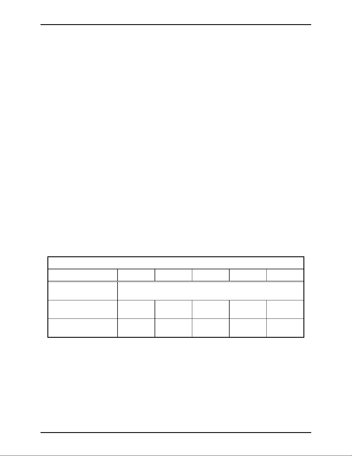
General Wire Ty pes
24 AWG 22 AWG 20 AWG 19 AWG 18 AWG
Maximum capacitance,
316,800 pF/mile
C (picofarads/mile)
Maximum resis tance,
271 171 107 85 67
R (ohms /mile)
*Ring signal loss,
-16 -12 -8 -6 -4
decibels (dB/ mi l e)
*Nominal ring signal is 98 dB @ 10 feet.
\\s_eng\gtc proddoc s \st andard iom s - current release\42004 instr. manuals \ 42004-178d. doc
03/06
Page 4

Pub. 42004-178D
Model 263 Isolation Barrier Unit (IBU) Page: 4 of 13
System Setup
GAI-Tronics recommends taking the following steps to ensure a safe and trouble-free installation:
1. Install the Model 263 Isolation Barrier Unit (IBU) and wire it completely, except for the hazardous
area signal wires.
WARNING
The unit must be wired in accordance with Pub. 42004-380, Control
Drawing 73242, to ensure intrinsic safety.
2. Next, temporarily connect the I.S. telephone to the IBU with a short pair of conductors, and operate
the unit by making a test phone call. If any problems are detected, see the Troubleshooting section.
3. Call the I.S. telephone from another telephone, and adjust the
RING PITCH (located on the IB U) t o
the desired pitch. See Figure 2 for location.
4. Disconnect the I.S. telephone and install it in the intended permanent location.
WARNING
The unit must be wired in accordance with Pub. 42004-380, Control
Drawing 73242, to ensure intrinsic safety.
5. Make a call from the I.S. telephone. If any problems are detected, see the Troubleshooting section.
\\s_eng\gtc proddoc s \st andard iom s - current release\42004 instr. manuals \ 42004-178d. doc
03/06
Page 5
Pub. 42004-178D
Model 263 Isolation Barrier Unit (IBU) Page: 5 of 13
Figure 2. Rear of IBU enclosure with cover removed
\\s_eng\gtc proddoc s \st andard iom s - current release\42004 instr. manuals \ 42004-178d. doc
03/06
Page 6

Pub. 42004-178D
Model 263 Isolation Barrier Unit (IBU) Page: 6 of 13
Mounting
1. Remove the front panel by loosening the four front captive screws.
2. Refer to Figur e 3 . Determin e w hich of the co nduit loca tions is to b e u sed. D rill spots have b e e n
provided for use with a chassis punch or hole saw. Using a hole saw is recommended.
3. One 0.280-inch diameter hole is located in each corner of the rear enclosure. Install the rear
enclosure to a wall of an ap prop riate surface t hrou gh the s upplied mounting ho les.
4. Refer to Pub. 42004-380, Control Drawing 73242, for wiring details.
N
OTE: Telephone system wire must be connected to the Isolation Barrier Unit only and not directly
to the I.S. telephone. Battery backup connection is not required for operation of the Model 262-001
and 272-001 I.S. Phones. If battery backup is desired, please consult the factory for specifications.
5. Apply power and test telephone operation.
6. Refer to t h e Troubleshootin g section of prob lems are det e c ted.
When p roper operat ion has been verif ied, replace the cover and secure it by tighten ing the four captive
screws.
\\s_eng\gtc proddoc s \st andard iom s - current release\42004 instr. manuals \ 42004-178d. doc
03/06
Page 7

Pub. 42004-178D
Model 263 Isolation Barrier Unit (IBU) Page: 7 of 13
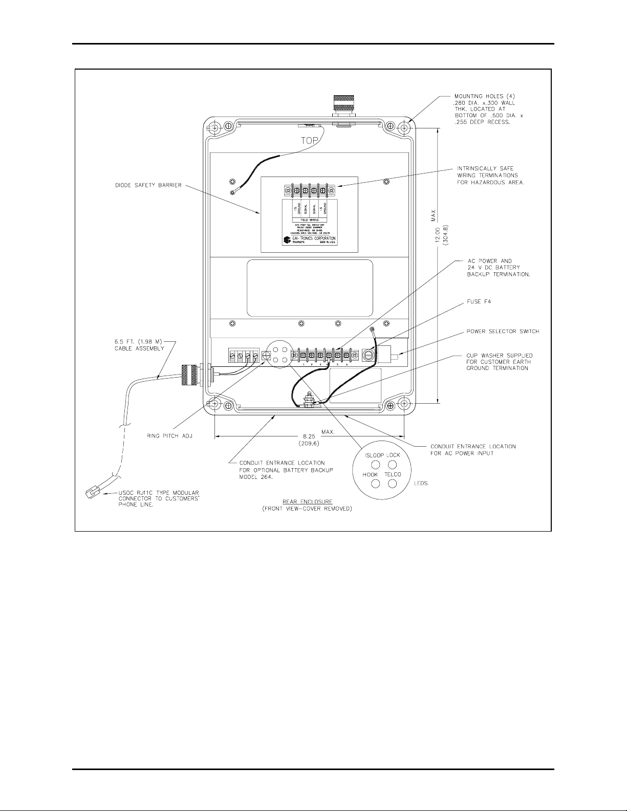
Figure 3. Model 263 Isolation Barrier Unit dimensions
Operation
The Model 263 Isolation Barrier Unit requires no operator intervention for routine functions.
\\s_eng\gtc proddoc s \st andard iom s - current release\42004 instr. manuals \ 42004-178d. doc
03/06
Page 8

Pub. 42004-178D
Model 263 Isolation Barrier Unit (IBU) Page: 8 of 13
Maintenance
This section inclu des two trou bles hooting c harts desi gned t o quickly p inpoint the sou rce o f problems.
Troubl eshooting
NOTE: It may be advantageous to temporarily connect an I.S. telephone panel directly to the output
terminals of the Model 263 IBU when troubleshooting. Then, using the charts below, the cause of the
problem should be more easily determined.
Non-E quipment Rel ated Problems
Problem Solution
The I.S. phone is inactive with
no light s on the IBU when t he
phone is off-hook.
The I.S. phone has no dial tone.
The lights on the IBU flash
randomly.
1. Check the ac power to the Model 263 IBU.
2. Check the ac fuse F4 at the Model 263 IBU.
3. Ens ur e there is no wiri ng open at the I.S. p ho ne.
1. If the I.S. phone has a wiring short, the IBU lights will be lit in
the following pattern: O =
ISLOOP O LOCK
On, P = Off
P
HOOK P TELCO
P
2. If the TELCO line has an open, the IBU lights will be lit in the
following pattern: : O =
ISLOOP O LOCK
On, P = Off
O
HOOK O TELCO
P
The I.S. phone ha s an inter mittent wiring shor t. The short ma y be
between the conductors or either/both conductor(s) to ground/shield.
\\s_eng\gtc proddoc s \st andard iom s - current release\42004 instr. manuals \ 42004-178d. doc
03/06
Page 9

Pub. 42004-178D
Model 263 Isolation Barrier Unit (IBU) Page: 9 of 13
Equipm ent-Rel ated Pro blems
Problem Solution
There is no incoming ring tone. 1. Check the I.S. telephone panel.
2. Check the Model 263 IBU.
No receiver audio, no sidetone,
and cannot hear touch tones
when pressed.
1. Check the I.S. telephone panel.
2. Check the Model 263 IBU.
3. There may be a wiring open or a short in t he connecting c abl e.
Ca nnot dial out , but c an hear
touch tones when pressed.
1. Check the Model 263 IBU.
2. There is no TELCO connection or it is faulty.
I.S. phone appears inactive. 1. Check the I.S. telephone panel.
2. Check the ac fuse F4 at the Model 263 IBU.
3. Ensure there is no wiring open in the connecting cable or at the I.S.
telephone.
CAUTION
Any field repa irs on the intrinsically-safe des ign of the phone are st rictly prohi b ited. Any such
cha nge will void ALL hazardous app rovals . Please co nta c t the GAI - Tr onics F ield Service Department a t
800-492-1212 inside the USA or 610-777-1374 outside the USA for the Regional Service Center closest
to you.
\\s_eng\gtc proddoc s \st andard iom s - current release\42004 instr. manuals \ 42004-178d. doc
03/06
Page 10

Pub. 42004-178D
Model 263 Isolation Barrier Unit (IBU) Page: 10 of 13
Lightning Protecti on
Telephone lines are susceptible to lightning strikes and must be properly protected and maintained. Onpremise line protection is usually provided at the building entrance by the responsible telephone company
when it is installed. T his protection is o f ten n e g lected after installatio n.
Degradation of conventional protection, such as carbon blocks or gas discharge types, will occur with
each lightni ng strike. To ensure sa fe operat ion, p rotec tive e lemen ts should be replaced freque ntly and
checked for proper connection and grounding. Gas discharge types are by far the most robust, costeffective mea ns of protectio n.
The regist ered I.S. equipment meets all isolation an d safety requirements of FCC, Part 6 8, DOC CS-0 3,
UL 913, and CSA C22.2-No. 157. However, lightning strikes are not predictable or considered to be a
condition of fault likely to occur in practice as defined by the guidelines for intrinsic safety. Therefore, it
is imperative that the user employ and maintain a proper lightning protection scheme. This is true for all
hazardous area equipment and all telecommunications equipment subject to lightning.
Figure 4. Example of a lightning protection design
\\s_eng\gtc proddoc s \st andard iom s - current release\42004 instr. manuals \ 42004-178d. doc
03/06
Page 11

Pub. 42004-178D
Model 263 Isolation Barrier Unit (IBU) Page: 11 of 13
Specification s
General/Environmental
Location (Model 263 IBU) ......................................................... Ordinary (non-classified) indoor/outdoor
FCC Registration Number .................................................................................... ADGUSA-65066-TE-E
Ringer Equivalence Number (REN)................................................................................................... 0.4B
IC Certification Number (Canada).......................................................................................... 822 4541 A
Load number (LN) (Canada)................................................................................................................. 14
Connecting method (Canada)........................................................................................................ CA11A
Operating temperature range............................................................ -40° F to +140° F (-40° C to +60° C)
Relative humidity.................................................................................. 95% (non-condensing) maximum
Maximum safe wiring distance between IBU and I.S. telephone
Standard wire types......................................................................................................................... 1 mile
Using GTC 60059-001 conductor............................................................................................... 1.5 miles
Using GTC 60021-301 conductor............................................................................................... 1.5 miles
Wiring
Construction.......................................................................................................................... Twiste d pair
*Type.......................................................................................................................................... Shielded
Conductor size (minimum)......................................................................................................... 24 AWG
Wiring loop resistance (maximum)............................................................................................ 275 ohms
Wiring capacitance (maximum).................................................................................................. 0.316 uF
*Shielded cable is required where multiple I.S. telephone wires are routed together.
Approvals
When connected according with Pub. 42004-380, Control Drawing 73242:
North America...............................................................................Div. 1, Class I, Groups A, B, C, and D;
Class II, Gr oups E, F, and G; Clas s III;
Div. 2 (same Cla sses and Group s as Di v. 1)
\\s_eng\gtc proddoc s \st andard iom s - current release\42004 instr. manuals \ 42004-178d. doc
03/06
Page 12

Pub. 42004-178D
Model 263 Isolation Barrier Unit (IBU) Page: 12 of 13
Model 263 Isola tion Barrier Unit
Electrical /Acoustical
Telephone Network Interface.................(2-wire)....................................... BELL Pub. 61100 Compatible
(4-wire)........................................................... See 4-wire option
AC power input.....................................Voltage (selectable) ..................................................... 90-132 V
180-240 V
Frequency...................................................................................................................... 47-63 Hz
Current ....................................................................................................... 0.5 amps (maximum)
Ringer pitch adjust .............................................................................................. 1 kHz - 8 kHz (nominal)
Intrinsically safe Interface
Voltage (maximum)........................................................................................................... 8 volts
Resistance (minimum).................................................................................................... 66 ohms
Current limited (maximum).............................................................................................. 136 mA
Indicators
I.S. Loop Current.......................................................................................................... I.S. LOOP (GRN)
I.S. Lock Detect............................................................................................................ I.S. LOCK (GRN)
Telephone Line Loop Current............................................................................................ TELCO (YEL)
Hook.................................................................................................................................. HOOK (YEL)
Mechanical
Housing construction........................................................................................ Glass-reinforced polyester
Housing dimensions............................... 9.39 W × 13.16 H × 7.46 D inches; (238.5 × 334.3 × 189.5 mm)
Enclosure rating (UL)................................................................................................ Type 3R (rainproof)
Weight .......................................................................................................................... 8.5 lbs. (3.86 kg)
Model 2 63 IBU 4-Wi re Optio n Interfac e
Receive (TB2-1, 2)................................................................................................................. Dry (No dc)
Signal Level....................................................................................................... 0 dBm (nominal)
+3 dBm (maximum
Transmit (TB2-3, 4)........................................................................................................................... Wet
DC Loop Current................................................................................................... 20 mA-70 mA
Signal Level....................................................................................................... 0 dBm (nominal)
Ring Voltage Input............................................................................................... 40 V-150 Vrms
\\s_eng\gtc proddoc s \st andard iom s - current release\42004 instr. manuals \ 42004-178d. doc
03/06
Page 13

Pub. 42004-178D
Model 263 Isolation Barrier Unit (IBU) Page: 13 of 13
Model 262-001 Ind oor /Model 272-001 O utdoor I.S. T elephones
Electrical /Acoustical
Electrical specifications (nominal)........................................................................................ 12 V, 12 mA
Ringer performance (typical)........................................................................................... 98 dB @ 10 feet
Frequency (adjustable at the IBU)........................................................... 1 kHz to 8 kHz (typical)
Ring signal loss (18 AWG).......................................................................................... -4 dB/mile
Signaling....................................................................................................................................... DTMF
Transmission path (2-conductor) ............................................................................................. Full duplex
Microphone....................................................................................................... Dynamic noise-canceling
Earpiece............................................................................................................... Hearing aid compatible
Output (0 dBm @ IBU TELCO Line) ......................................................... 105 dB SPL @ 1 kHz
Audio signal loss (18 AWG)..................................................................................... -1.3 dB/mile
N
OTE: Must be connected in accordance with Pub. 42004-380, Control Drawing 73242.
Mechanical
Housing construction........................................................................................ Glass-reinforced Polyester
Housi n g di men s i ons
Model 262-001 ...... ..................... 8.02 W × 9.52 H × 6.86 D inches; (203.7 × 241.8 × 174.2 mm)
including handset; 3.86 D (98 mm), without handset
Model 272-001 .......................... 9.39 W × 13.16 H × 7.46 D inches; (238.5 × 334.3 × 189.5 mm)
Enclosure rating (UL)
Model 262-001 ............................................................................................................... Type 12
Model 272-001 ............................................................................................. Type 3R (rainproof)
Weight
Model 262-001 .................................................................................................. 5.0 lbs. (2.27 kg)
Model 272-001 ................................................................................................ 10.0 lbs. (4.53 kg)
Approv als
When connected in accordance with Pub. 42004-380, Control Drawing 73242:
UL/cUL.........................................................................................Class I, Div. 1, Groups A, B, C, and D;
Class II, Div. 1, Groups E, F, a nd G; Clas s III;
\\s_eng\gtc proddoc s \st andard iom s - current release\42004 instr. manuals \ 42004-178d. doc
03/06
Page 14

Warranty
Equipment. GAI-Tronics warrants for a period of one (1) year from the date of shipment, that any
GAI-Tronics equipment supplied hereunder shall be free of defects in material and workmanship, shall
comply with the then-current product specifications and product literature, and if applicable, shall be fit
for the purpose specified in the agreed-upon quotation or proposal document. If (a) Seller’s goods prove
to be defective in workmanship and/or material under normal and proper usage, or unfit for the purpose
specified and agreed upon, and (b) Buyer’s claim is made within the warranty period set forth above,
Buyer may return such goods to GAI-Tronics’ nearest depot repair facility, freight prepaid, at which time
they will be repaired or replaced, at Seller’s option, without charge to Buyer. Repair or replacement shall
be Buyer’s sole and exclusive remedy. The warranty period on any repaired or replacement equipment
shall be the greater of the ninety (90) day repair warranty or one (1) year from the date the original
equipment was shipped. In no event shall GAI-Tronics warranty obligations with respect to equipment
exceed 100% of the total cost of the equipment supplied hereunder. Buyer may also be entitled to the
manufacturer’s warranty on any third-party goods supplied by GAI-Tronics hereunder. The applicability
of any such third-party warranty will be determined by GAI-Tronics.
Services. Any services GAI-Tronics provides hereunder, whether directly or through subcontractors,
shall be performed in accordance with the standard of care with which such services are normally
provided in the industry. If the services fail to meet the applicable industry standard, GAI-Tronics will
re-perform such services at no cost to buyer to correct said deficiency to Company's satisfaction provided
any and all issues are identified prior to the demobilization of the Contractor’s personnel from the work
site. Re-performance of services shall be Buyer’s sole and exclusive remedy, and in no event shall GAITronics warranty obligations with respect to services exceed 100% of the total cost of the services
provided hereunder.
Warranty Periods. Every claim by Buyer alleging a defect in the goods and/or services provided
hereunder shall be deemed waived unless such claim is made in writing within the applicable warranty
periods as set forth above. Provided, however, that if the defect complained of is latent and not
discoverable within the above warranty periods, every claim arising on account of such latent defect shall
be deemed waived unless it is made in writing within a reasonable time after such latent defect is or
should have been discovered by Buyer.
Limitations / Exclusions. The warranties herein shall not apply to, and GAI-Tronics shall not be
responsible for, any damage to the goods or failure of the services supplied hereunder, to the extent
caused by Buyer’s neglect, failure to follow operational and maintenance procedures provided with the
equipment, or the use of technicians not specifically authorized by GAI-Tronics to maintain or service the
equipment. THE WARRANTIES AND REMEDIES CONTAINED HEREIN ARE IN LIEU OF AND
EXCLUDE ALL OTHER WARRANTIES AND REMEDIES, WHETHER EXPRESS OR IMPLIED BY
OPERATION OF LAW OR OTHERWISE, INCLUDING ANY WARRANTIES OF
MERCHANTABILITY OR FITNESS FOR A PARTICULAR PURPOSE.
Return Policy
If the equipment requires service, contact your Regional Service Center for a return authorization number
(RA#). Equipment should be shipped prepaid to GAI-Tronics with a return authorization number and a
purchase order number. If the equipment is under warranty, repairs or a replacement will be made in
accordance with the warranty policy set forth above. Please include a written explanation of all defects to
assist our technicians in their troubleshooting efforts.
Call 800-492-1212 (inside the USA) or 610-777-1374 (outside the USA) for help identifying the
Regional Service Center closest to you.
(Rev. 10/06)
 Loading...