

Page 1

Pub. 42004-476A
GAI-TRONICS® CORPORATION
A HUBBELL COMPANY
Model 239WM-001 & 239WM-002
Slim Wall-Mount Stanchions
Confidentiality Notice
This manual is provided solely as an operational, installation, and maintenance guide and contains
sensitive business and technical information which is confidential and proprietary to GAI-Tronics.
GAI-Tronics retains all intellectual property and other rights in or to the information contained herein,
and such information may only be used in connection with the operation of your GAI-Tronics product or
system. This manual may not be disclosed in any form, in whole or in part, directly or indirectly, to any
third party.
General Information
The Model 239WM-001 Stainless Steel Slim Wall-Mount Stanchion is designed to house GAI-Tronics’
Flush-Mount Emergency Analog or VoIP Telephones. The Model 239WM-002 Stanchion is designed to
house GAI-Tronics’ WiFi Telephones.
The following components are supplied with both models of the Slim Wall-Mount Stanchions:
Qty Description
1 Stanchion Enclosure
1 Gasketed blank cover
1 Integral Constant-On Strobe with Protective Guard
1 Integral WiFi antenna with connecting cable (Model 239WM-002 only)
2 Access hole gaskets
4 Rubber washers
2 Stainless steel hole plugs
Installation
Safety Guidelines
When installing GAI-Tronics’ telephone equipment, please adhere to the following guidelines to ensure
the safety of all personnel:
NEVER install telephone wiring during a lightning storm.
NEVER install telephone jacks in wet locations unless the jack is specifically designed for wet
locations.
NEVER touch uninsulated telephone wires or terminals unless the telephone line has been
disconnected at the network interface.
USE CAUTION when installing or modifying telephone lines.
GAI-Tronics Corporation 400 E. Wyomissing Ave. Mohnton, PA 19540 USA
610-777-1374 800-492-1212 Fax: 610-796-5954
ISIT WWW.GAI-TRONICS.COM FOR PRODUCT LITERATURE AND MANUALS
V
Page 2

Pub. 42004-476A
Model 239WM-001 & 239WM-002 Slim Wall-Mount Stanchions Page
2 of 9
Installation Guidelines
GAI-Tronics’ Emergency Telephones are not designed to be installed in parallel or to be “party-
lined.” Any such installation can cause programming difficulties, premature disconnection of calls,
or stations that may not respond when activated. GAI-Tronics highly recommends that one telephone
line (PBX extension or CO line) be allocated for each unit.
GAI-Tronics highly recommends that a telephone line surge suppressor be installed to guard against
lightning strikes. Please consult Distributor Sales at 800-838-9313 if further information is required.
Sealed fittings should be installed at all cable entry points to prevent liquids from entering the unit.
Secure the front cover using the screws and washers provided. Torque the screws to 10–12 in-lbs.
(1.13–1.36 n-m).
This permanently connected apparatus must have a 15-amp circuit breaker incorporated in the
electrical installation of the building.
Mounting
NOTE
GAI-Tronics flush-mount telephones are equipped with a metal back box that is
not required and should be removed prior to installing the telephone in the stanchion.
1. Cables can enter the stanchion either through access holes in the back or the bottom of the unit. Hole
caps are provided to seal the holes that are not used. The Model 239WM-00x is provided with two
hole caps installed in the bottom of the enclosure. If entry is from the back of the unit, install two
gaskets (provided) to seal around the holes. If conduit entrance is desired into the bottom of the
unit, remove the hole caps from the bottom two holes and install them in the two holes located on the
back of the enclosure.
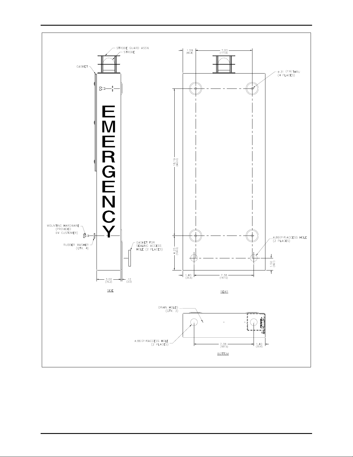
2. Mount the enclosure on a flat wall surface using the four 5/16-inch (0.312) diameter holes as shown
in Figure 1. Four rubber washers are provided to ensure weather-tight sealing.
N
OTE: Mounting hardware is not provided.
e:\standard ioms - current release\42004 i nstr. manuals\42004-476a.doc
08/14
Page 3
Pub. 42004-476A
Model 239WM-001 & 239WM-002 Slim Wall-Mount Stanchions Page
3 of 9
Figure 1. Model 239MW-001/-002 Mounting Details
e:\standard ioms - current release\42004 i nstr. manuals\42004-476a.doc
08/14
Page 4

Pub. 42004-476A
Model 239WM-001 & 239WM-002 Slim Wall-Mount Stanchions Page
4 of 9
Model 239WM-001 Stanchion
Analog Telephone Wiring
Refer to Figure 2 and Figure 3.
1. Install the telephone line surge suppressor (customer-supplied) on the telephone line, if applicable.
2. Install the surface-mount jack with adhesive pad that is provided with each Flush-Mount Emergency
Telephone by adhering it to the back box at the lower edge.
3. The telephone line must enter the stanchion through one of the holes on the right hand side of the
unit when viewed from the front. Plug the telephone line into the surface-mounted jack assembled in
step 2.
4. The ac power line must enter the stanchion through one of the holes on the left side of the unit when
viewed from the front. Secure the wires to the terminal block as noted on the label.
5. Connect the violet (V) and orange (O) beacon wires inside the stanchion to TB2 on the E-phone
PCBA as shown in Figure 2.
6. Plug the RJ11 modular connector from the telephone into the surface-mount jack installed in step 2.
OTE: Steps 2 and 6 may be skipped and the incoming telephone line can connect directly to TB1 of the
N
telephone, if desired.
e:\standard ioms - current release\42004 i nstr. manuals\42004-476a.doc
08/14
Figure 2.
Page 5

Pub. 42004-476A
Model 239WM-001 & 239WM-002 Slim Wall-Mount Stanchions Page
5 of 9
e:\standard ioms - current release\42004 i nstr. manuals\42004-476a.doc
08/14
Figure 3.
Page 6

Pub. 42004-476A
Model 239WM-001 & 239WM-002 Slim Wall-Mount Stanchions Page
VoIP Telephone Wiring
6 of 9
Refer to Figure 3 and Figure 4.
1. The Ethernet cable must enter the stanchion through one of the holes on the right hand side of the
unit when viewed from the front.
2. The ac power line must enter the stanchion through one of the holes on the left side of the unit when
viewed from the front. Secure the wires to the terminal block as noted on the label. See Figure 3.
3. Install the violet (V) and orange (O) beacon wires from inside the stanchion to P10 on the VoIP
Carrier PCBA as shown in Figure 4.
4. If utilizing PoE, connect the power to the system as indicated in the PoE manual. If utilizing local
power, connect the positive conductor to the (+) terminal and the negative conductor to the (−)
terminal of P5 on the telephone (customer-supplied wiring). Connect the positive conductor to the
(+) terminal (3) and the negative conductor to the (−) terminal (4) of the TB1 located in the top
section of the stanchion. See Figure 5 and Figure 6 for 24 V dc wiring as well as the appropriate
telephone installation manuals.
5. Plug the Ethernet cable into the VoIP Circuit PCBA as shown in Figure 4.
e:\standard ioms - current release\42004 i nstr. manuals\42004-476a.doc
08/14
Figure 4.
Page 7

Pub. 42004-476A
Model 239WM-001 & 239WM-002 Slim Wall-Mount Stanchions Page
7 of 9
Model 239WM-002 Stanchion
VoIP/WiFi Telephone Wiring
Refer to Figure 5 and Figure 6.
1. The ac power line must enter the stanchion through one of the holes on the left side of the unit when
viewed from the front. Secure the wires to the terminal block as noted on the label.
2. Install the violet (V) and orange (O) beacon wires from inside the stanchion to P10 on the WiFi
Carrier PCBA as shown in Figure 5.
3. Attach the connector from the WiFi antenna wire to the antenna connector mounted on the WiFi
Carrier PCBA.
4. WiFi telephones require a local power source to operate. Each WiFi Telephone includes terminal
block P5 for connection of local power to the telephone. Connect the positive conductor to the (+)
terminal and the negative conductor to the (−) terminal of P5 on the telephone (customer-supplied
wiring). Connect the positive conductor to the (+) terminal (3) and the negative conductor to the (−)
terminal (4) of the TB1 located in the top section of the stanchion. See Figure 5 and Figure 6 for 24
V dc wiring as well as the appropriate telephone installation manuals.
e:\standard ioms - current release\42004 i nstr. manuals\42004-476a.doc
08/14
Figure 5.
Page 8

Pub. 42004-476A
Model 239WM-001 & 239WM-002 Slim Wall-Mount Stanchions Page
8 of 9
e:\standard ioms - current release\42004 i nstr. manuals\42004-476a.doc
08/14
Figure 6.
Page 9

Pub. 42004-476A
Model 239WM-001 & 239WM-002 Slim Wall-Mount Stanchions Page
9 of 9
Specifications
Mechanical
Construction ........................................................................... Type 304 stainless steel, 0.063-inch thickness
Finish ........................................................................................................................ Brushed and passivated
Mounting ........................................... Four 5/16-inch (0.312) diameter mounting holes in mounting bosses
Connections .......................................................................................................... See “Installation” section
Dimensions .............................. 26.54 H 10.18 W 3.32 D inches (674.1 258.6 84.2 mm) maximum
Shipping weight ................................................................................................ 13.25 lbs.(6.0 kg) maximum
Electrical
Input voltage .................................................................................................................................... 120 V ac
Power supply rating .............................................................................................. 24 V dc/ 0.83 A, 20 watts
Input current .......................................................................................................................... 0.3 A maximum
Environmental
Temperature range .............................................................................................................. –40º C to +60º C
Weatherproof rating ............................................................................................................... UL50, Type 3R
Approval Standards
Safety of Information Technology Equipment ..................................................................... UL/CSA 60950
e:\standard ioms - current release\42004 i nstr. manuals\42004-476a.doc
08/14
Page 10

Warranty
Equipment. GAI-Tronics warrants for a period of one (1) year from the date of shipment, that any
GAI-Tronics equipment supplied hereunder shall be free of defects in material and workmanship, shall
comply with the then-current product specifications and product literature, and if applicable, shall be fit
for the purpose specified in the agreed-upon quotation or proposal document. If (a) Seller’s goods prove
to be defective in workmanship and/or material under normal and proper usage, or unfit for the purpose
specified and agreed upon, and (b) Buyer’s claim is made within the warranty period set forth above,
Buyer may return such goods to GAI-Tronics’ nearest depot repair facility, freight prepaid, at which time
they will be repaired or replaced, at Seller’s option, without charge to Buyer. Repair or replacement shall
be Buyer’s sole and exclusive remedy. The warranty period on any repaired or replacement equipment
shall be the greater of the ninety (90) day repair warranty or one (1) year from the date the original
equipment was shipped. In no event shall GAI-Tronics warranty obligations with respect to equipment
exceed 100% of the total cost of the equipment supplied hereunder. Buyer may also be entitled to the
manufacturer’s warranty on any third-party goods supplied by GAI-Tronics hereunder. The applicability
of any such third-party warranty will be determined by GAI-Tronics.
Services. Any services GAI-Tronics provides hereunder, whether directly or through subcontractors,
shall be performed in accordance with the standard of care with which such services are normally
provided in the industry. If the services fail to meet the applicable industry standard, GAI-Tronics will
re-perform such services at no cost to buyer to correct said deficiency to Company's satisfaction provided
any and all issues are identified prior to the demobilization of the Contractor’s personnel from the work
site. Re-performance of services shall be Buyer’s sole and exclusive remedy, and in no event shall GAITronics warranty obligations with respect to services exceed 100% of the total cost of the services
provided hereunder.
Warranty Periods. Every claim by Buyer alleging a defect in the goods and/or services provided
hereunder shall be deemed waived unless such claim is made in writing within the applicable warranty
periods as set forth above. Provided, however, that if the defect complained of is latent and not
discoverable within the above warranty periods, every claim arising on account of such latent defect shall
be deemed waived unless it is made in writing within a reasonable time after such latent defect is or
should have been discovered by Buyer.
Limitations / Exclusions. The warranties herein shall not apply to, and GAI-Tronics shall not be
responsible for, any damage to the goods or failure of the services supplied hereunder, to the extent
caused by Buyer’s neglect, failure to follow operational and maintenance procedures provided with the
equipment, or the use of technicians not specifically authorized by GAI-Tronics to maintain or service the
equipment. THE WARRANTIES AND REMEDIES CONTAINED HEREIN ARE IN LIEU OF AND
EXCLUDE ALL OTHER WARRANTIES AND REMEDIES, WHETHER EXPRESS OR IMPLIED BY
OPERATION OF LAW OR OTHERWISE, INCLUDING ANY WARRANTIES OF
MERCHANTABILITY OR FITNESS FOR A PARTICULAR PURPOSE.
Return Policy
If the equipment requires service, contact your Regional Service Center for a return authorization number
(RA#). Equipment should be shipped prepaid to GAI-Tronics with a return authorization number and a
purchase order number. If the equipment is under warranty, repairs or a replacement will be made in
accordance with the warranty policy set forth above. Please include a written explanation of all defects to
assist our technicians in their troubleshooting efforts.
Call 800-492-1212 (inside the USA) or 610-777-1374 (outside the USA) for help identifying the
Regional Service Center closest to you.
(Rev. 10/06)
 Loading...