

Page 1

Pub. 42003-187A
GAI-TRONICS® CORPORATION
A HUBBELL COMPANY
Pole-Mounting Bracket Kit
Model 238
Confidentiality Notice
This manua l is provide d sole ly as an operatio nal, installation, and ma inte nance guide and conta ins
sensitive business and t e chnic al infor ma tion w hich is conf ident ial and pr op riet ary to GAI-Tro nics.
GAI-Tronics retains all intellectual property and other rights in or to the information contained herein,
and such information may only be used in connection with the operation of your GAI-Tronics product or
system. This manu al may not be dis clos e d in any form, in whole or in pa rt, direct ly or i ndir ectly, to a ny
third pa r ty.
General Information
The Model 238 Pole-Mounting Kit is designed to mount the GTC Model WCB104 Wireless Call Box to a
4-inch nominal O.D. steel pole that has been installed in accordance with the applicable state highway
regulations for emergency access equipment. When this bracket is mounted at the correct height, it
supports the call box so that its highest auto-dial button is no higher than 48 inches above the ground.
An additional kit is also necessary to mount highway signs and mile markers to the pole. The hardware
nec essary to inst all either applicat ion is p rovi ded, and is lis ted b elow:
Qty Description
1 Bracket
2 U-bolts, 304 stainless steel
2 Bolts, 1/2-13 (used for call box installation)
4 Bolts, 1/4-20 (used for sign mounting)
4 Lock washers, split-ring, 304 stainless steel
2 Gasket, 1-inch O.D. (used for call box installation)
2 Gasket, 2-inch O.D. (used for call box installation)
4 Washers, flat, ¼-inch (used for sign mounting)
4 Nuts, 304 stainless steel
Installation
The Model 238 Pole-Mounting Bracket Kit can be used to mount either the call box or the highway mile
markers. Choose the app ropriate hardware p rovi ded for ea c h app lic ati on as f ollows :
GAI-Tronics Corporation P.O. Box 1060, Readi ng, PA 19607-1060 USA
610-777-1374 800-492-1212 Fax: 610-796-5954
ISIT WWW.GAI-TRONICS.COM FOR PRODUCT LITERATURE AND MANUALS
V
Page 2
Pub. 42003-187A
M
ODEL 238 Pole-Mounting Br acket Kit Page: 2 of 3
Install the Pole- Mounting Bracke t for the Call Box
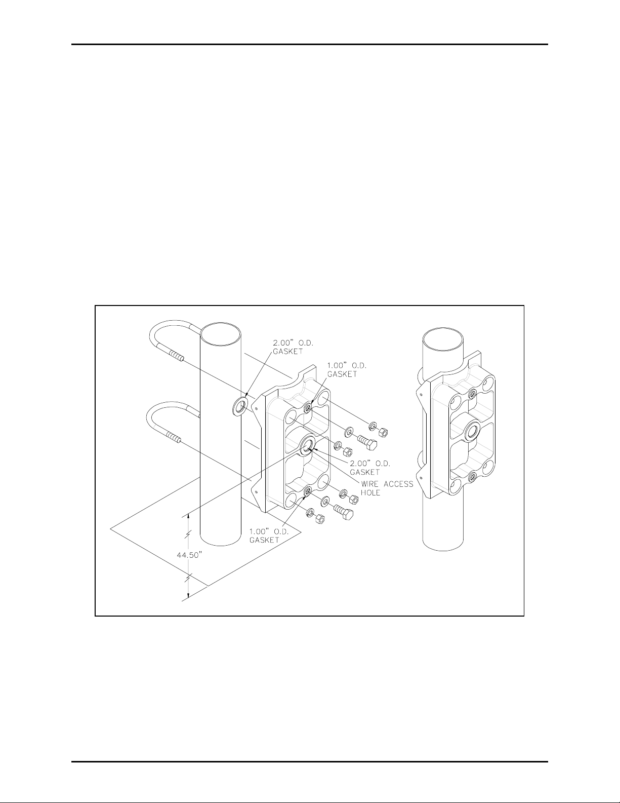
1. Install the supplied gaskets as shown in Figure 1. Remove the paper backing from the gaskets and
position them on the mounting bracket as shown. Place a 1-inch O.D. gaskets around each of the
½-inch mounting holes. Place one of the 2-inch O.D. gaskets on each side of the bracket over the
1.125-inch hole.
2. Mount the bracket by installing both supplied U-bolts around the exterior of the pole and through the
bracket. Ensure that the bracket wire access hole is located no more than 44.5 inches above the
ground wh ere th e c all - box user is expected t o sta nd. Refer t o Figure 1 sh own b el ow.
3. Tighten the nuts on the U-bolts to a 20 foot-pound torque using a torque wrench.
4. Using a 1- inc h diameter bit , drill throu gh the center hole of the mountin g brack et into the pole. The
mountin g b rac ket ser ves as a drill guid e. Do not dril l through the rear sid e of the p ole.
5. The r e main ing two ½-13 bolt s and t wo flat was hers are p rovid e d for mounting the call box. Refer to
GTC Publication 42004-327A for call box mounting instructions
Figure 1. Call Box Mounting Bracket Assembly
\\s_eng\gtc proddoc s \st andard iom s - current release\42003 kit manuals \ 42003-187a.doc
12/00
Page 3

Pub. 42003-187A
M
ODEL 238 Pole-Mounting Br acket Kit Page: 3 of 3
Install the Sign Mo unting Bracket
1. Mount the bracket by installing both supplied U-bolts around the exterior of the pole and through the
bracket. Place the bracket at the desired height. Refer to Figure 2 below.
Note that this bracket does not
require drilling an access hole into the pole.
2. Inst all t he four lock was hers and nut s on the U-bolts and t ighten the nuts to 20 f oot-pou nds using a
torque wrench.
3. Place the left side sign against the bracket and secure it using two ¼-20 bolts and two flat washers.
Place the right side sign against the bracket and secure it using two ¼-20 bolts and two flat washers.
Figure 2. Sign Mounting Bracket Assembly
\\s_eng\gtc proddoc s \st andard iom s - current release\42003 kit manuals \ 42003-187a.doc
12/00
Page 4

Warranty
Equipment. GAI-Tronics warrants for a period of one (1) year from the date of shipment, that any
GAI-Tronics equipment supplied hereunder shall be free of defects in material and workmanship, shall
comply with the then-current product specifications and product literature, and if applicable, shall be fit
for the purpose specified in the agreed-upon quotation or proposal document. If (a) Seller’s goods prove
to be defective in workmanship and/or material under normal and proper usage, or unfit for the purpose
specified and agreed upon, and (b) Buyer’s claim is made within the warranty period set forth above,
Buyer may return such goods to GAI-Tronics’ nearest depot repair facility, freight prepaid, at which time
they will be repaired or replaced, at Seller’s option, without charge to Buyer. Repair or replacement shall
be Buyer’s sole and exclusive remedy. The warranty period on any repaired or replacement equipment
shall be the greater of the ninety (90) day repair warranty or one (1) year from the date the original
equipment was shipped. In no event shall GAI-Tronics warranty obligations with respect to equipment
exceed 100% of the total cost of the equipment supplied hereunder. Buyer may also be entitled to the
manufacturer’s warranty on any third-party goods supplied by GAI-Tronics hereunder. The applicability
of any such third-party warranty will be determined by GAI-Tronics.
Services. Any services GAI-Tronics provides hereunder, whether directly or through subcontractors,
shall be performed in accordance with the standard of care with which such services are normally
provided in the industry. If the services fail to meet the applicable industry standard, GAI-Tronics will
re-perform such services at no cost to buyer to correct said deficiency to Company's satisfaction provided
any and all issues are identified prior to the demobilization of the Contractor’s personnel from the work
site. Re-performance of services shall be Buyer’s sole and exclusive remedy, and in no event shall GAITronics warranty obligations with respect to services exceed 100% of the total cost of the services
provided hereunder.
Warranty Periods. Every claim by Buyer alleging a defect in the goods and/or services provided
hereunder shall be deemed waived unless such claim is made in writing within the applicable warranty
periods as set forth above. Provided, however, that if the defect complained of is latent and not
discoverable within the above warranty periods, every claim arising on account of such latent defect shall
be deemed waived unless it is made in writing within a reasonable time after such latent defect is or
should have been discovered by Buyer.
Limitations / Exclusions. The warranties herein shall not apply to, and GAI-Tronics shall not be
responsible for, any damage to the goods or failure of the services supplied hereunder, to the extent
caused by Buyer’s neglect, failure to follow operational and maintenance procedures provided with the
equipment, or the use of technicians not specifically authorized by GAI-Tronics to maintain or service the
equipment. THE WARRANTIES AND REMEDIES CONTAINED HEREIN ARE IN LIEU OF AND
EXCLUDE ALL OTHER WARRANTIES AND REMEDIES, WHETHER EXPRESS OR IMPLIED BY
OPERATION OF LAW OR OTHERWISE, INCLUDING ANY WARRANTIES OF
MERCHANTABILITY OR FITNESS FOR A PARTICULAR PURPOSE.
Return Policy
If the equipment requires service, contact your Regional Service Center for a return authorization number
(RA#). Equipment should be shipped prepaid to GAI-Tronics with a return authorization number and a
purchase order number. If the equipment is under warranty, repairs or a replacement will be made in
accordance with the warranty policy set forth above. Please include a written explanation of all defects to
assist our technicians in their troubleshooting efforts.
Call 800-492-1212 (inside the USA) or 610-777-1374 (outside the USA) for help identifying the
Regional Service Center closest to you.
(Rev. 10/06)
 Loading...