

Page 1
Pub. 42003-111A
GAI-TRONICS® CORPORATION
A HUBBELL COMPANY
Subset Extension Cable Assembly
Replacement Kit
MODEL 12587-001
Confidentiality Notice
This manual is provided solely as an operational, installation, and maintenance guide and contains
sensitive business and technical information that is confidential and proprietary to GAI-Tronics. GAITronics retains all intellectual property and other rights in or to the information contained herein, and
such information may only be used in connection with the operation of your GAI-Tronics product or
system. This manual may not be disclosed in any form, in whole or in part, directly or indirectly, to any
third party.
General Information
NOTE: The use of this assembly with CSA-approved models will void the CSA approval.
Model 12587-001 Subset Extension Cable Assembly Replacement Kit is compatible with the following
stations:
Desk-edge Stations Flush-Mount Stations Desktop Stations
710-102 715-102 720-102
710-004 715-004 7205-102
7105-102 7155-102 726-102
7105-004 7155-004 7265-102
Model 12587-001 includes the following components:
Qty Description
1 Cable, 50-foot, 24-conductor, No. 24 AWG with a 24-position (P1) plug on one end
1 Wall plate, stainless steel with two mounting screws and 24-position, already-mounted receptacle
1 Receptacle (24-position) with cable clamp housing
2 Disengagement-prevention brackets with screws and nuts
1 PVC tubing, 1.5-inch piece
GAI-Tronics Corporation 400 E. Wyomissing Ave. Mohnton, PA 19540 USA
610-777-1374 800-492-1212 Fax: 610-796-5954
ISIT WWW.GAI-TRONICS.COM FOR PRODUCT LITERATURE AND MANUALS
V
Page 2
Pub. 42003-111A
M
ODEL 12587-001 SUBSET EXTENSION CABLE ASSEMBLY REPLACEMENT KIT Page 2 of 4
Installation as a W all Receptacle
1. Arrange the cable so that P1 is located at the amplifier enclosure, and the blunt end of the cable is
located at the wall receptacle. After all connections are made, P1 will plug into the receptacle at the
amplifier enclosure, and the blunt end of the cable will connect to the wall receptacle.
2. Install the 50-foot cable/plug assembly in the wall from the amplifier location to the desired wall
receptacle location in a nominal 2 3 1.5 inches minimum depth single gang electrical box. Check
the appropriate electrical code.
3. Cut the cable to the desired length, allowing adequate cable for the installation of the wall plate.
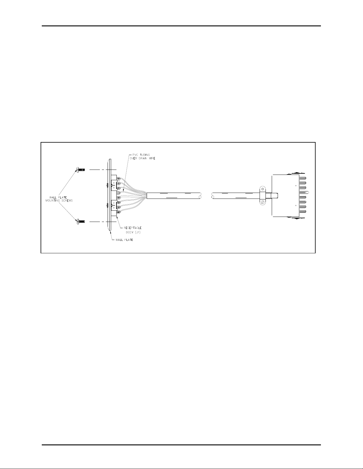
Figure 1. Installation as a Wall Receptacle
4. From the blunt end of the cable, strip 1.75 inches off from the cable jacket, and strip 0.25 inch off
from the insulation on the 24 individual wires. The cable contains one shielded pair of wires with a
drain wire. Trim the shield until it is even with the cable jacket. Twist the drain wire, and cover it
with the 1.5-inch PVC tubing (supplied) prior to soldering it to terminal 14 of receptacle J1.
5. See Figure 4 for proper wire color terminations. Solder all wire leads and drain wire to receptacle J1
on the wall plate as indicated in Figure 2. Make sure that there are no wire strands touching any
other terminations.
6. Install the wall plate using the two mounting screws provided.
7. Plug P1 into the amplifier enclosure and the subset plug into the wall receptacle J1. Be sure that the
connector housing latching tabs are properly in place.
f:\standard ioms - current release\42003 kit manuals\42003-111a.doc
10/12
Page 3

Pub. 42003-111A
M
ODEL 12587-001 SUBSET EXTENSION CABLE ASSEMBLY REPLACEMENT KIT Page 3 of 4
Installation as a Subset Extension Cord
1. Arrange the cable so that P1 is located at the amplifier enclosure or wall receptacle. After all the
connections are made, P1 will plug into the receptacle at the amplifier enclosure or wall receptacle,
and the blunt end of the cable will be wired to the 24-position receptacle (J1) and will plug into the
subset plug.
2. Cut the cable to the desired length needed to reach from the amplifier enclosure or wall receptacle to
the existing subset cable.
3. From the blunt end of the cable, strip the cable jacket off for 1.75 inches, and the 24-wire lead
jackets for 0.25 inch. Install the cable clamp housing on the cable prior to soldering the leads to the
receptacle J1 terminals.
4. The cable contains one shielded pair of wires with a drain wire. Trim the shield until it is even with
the cable jacket. Twist the drain wire, and cover it with the 1.5-inch PVC tubing (supplied) prior to
soldering terminal 14 of receptacle J1.
Figure 2. Installation as a Subset Extension
5. See Figure 4 for proper wire color terminations. Solder all wire leads and the drain wire to
receptacle J1 as indicated in Figure 1. Make sure that there are no wire strands touching any other
terminations.
6. Install the cable clamp housing over the receptacle body, and install the housing pins from opposite
sides of the housing, then tighten the cable clamp screws.
7. Plug P1 into the amplifier enclosure or wall receptacle.
f:\standard ioms - current release\42003 kit manuals\42003-111a.doc
10/12
Page 4

Pub. 42003-111A
M
ODEL 12587-001 SUBSET EXTENSION CABLE ASSEMBLY REPLACEMENT KIT Page 4 of 4
8. Plug the subset plug into receptacle J1. Attach the disengagement-prevention brackets and screw
together. See Figure 3.
Figure 3. Position of disengagement-prevention brackets
Figure 4. Wire Color Termination
f:\standard ioms - current release\42003 kit manuals\42003-111a.doc
10/12
Page 5

Warranty
Equipment. GAI-Tronics warrants for a period of one (1) year from the date of shipment, that any
GAI-Tronics equipment supplied hereunder shall be free of defects in material and workmanship, shall
comply with the then-current product specifications and product literature, and if applicable, shall be fit
for the purpose specified in the agreed upon quotation or proposal document. If (a) Seller’s goods prove
to be defective in workmanship and/or material under normal and proper usage, or unfit for the purpose
specified and agreed upon, and (b) Buyer’s claim is made within the warranty period set forth above,
Buyer may return such goods to GAI-Tronics nearest depot repair facility, freight prepaid, at which time
they will be repaired or replaced, at Seller’s option, without charge to Buyer. Repair or replacement shall
be Buyer’s sole and exclusive remedy. The warranty period on any repaired or replacement equipment
shall be the greater of the ninety (90) day repair warranty or one (1) year from the date the original
equipment was shipped. In no event shall GAI-Tronics warranty obligations with respect to equipment
exceed 100% of the total cost of the equipment supplied hereunder. Buyer may also be entitled to the
manufacturer’s warranty on any third-party goods supplied by GAI-Tronics hereunder. The applicability
of any such third-party warranty will be determined by GAI-Tronics.
Services. Any services GAI-Tronics provides hereunder, whether directly or through subcontractors,
shall be performed in accordance with the standard of care with which such services are normally
provided in the industry. If the services fail to meet the applicable industry standard, GAI-Tronics will reperform such services at no cost to buyer to correct said deficiency to Company's satisfaction provided
any and all issues are identified prior to the demobilization of the Contractor's personnel from the work
site. Re-performance of services shall be Buyer's sole and exclusive remedy, and in no event shall GAITronics warranty obligations with respect to services exceed 100% of the total cost of the services
provided hereunder.
Warranty Periods. Every claim by Buyer alleging a defect in the goods and/or services provided
hereunder shall be deemed waived unless such claim is made in writing within the applicable warranty
periods as set forth above. Provided, however, that if the defect complained of is latent and not
discoverable within the above warranty periods, every claim arising on account of such latent defect shall
be deemed waived unless it is made in writing within a reasonable time after such latent defect is or
should have been discovered by Buyer.
Limitations / Exclusions. The warranties herein shall not apply to, and GAI-Tronics shall not be
responsible for, any damage to the goods or failure of the services supplied hereunder, to the extent
caused by Buyer’s neglect, failure to follow operational and maintenance procedures provided with the
equipment, or the use of technicians not specifically authorized by GAI-Tronics to maintain or service the
equipment. THE WARRANTIES AND REMEDIES CONTAINED HEREIN ARE IN LIEU OF AND
EXCLUDE ALL OTHER WARRANTIES AND REMEDIES, WHETHER EXPRESS OR IMPLIED BY
OPERATION OF LAW OR OTHERWISE, INCLUDING ANY WARRANTIES OF
MERCHANTABILITY OR FITNESS FOR A PARTICULAR PURPOSE.
Return Policy
If the equipment requires service, contact your Regional Service Center for a return authorization number
(RA#). Equipment should be shipped prepaid to GAI-Tronics with a return authorization number and a
purchase order number. If the equipment is under warranty, repairs or a replacement will be made in
accordance with the warranty policy set forth above. Please include a written explanation of all defects to
assist our technicians in their troubleshooting efforts.
Call 800-492-1212 (inside the USA) or 610-777-1374 (outside the USA) for help identifying the
Regional Service Center closest to you.
(Rev. 10/06)
 Loading...