

Page 1

Pub. 42003-137A
GAI-TRONICS® CORPORATION
A HUBBELL COMPANY
Harness A ssembly Replacement Ki t
MODELS 12586-002, 12586-003, AND 12586-004
Confidentiality Notice
This manual is pr ovided s olely as a n op erat ional, installation, and maintenance guide and contains sens itive
bus ines s and t echnic al infor ma tion which is conf idential and propriet ary to GAI-Tronics. GAI - Tronic s
retains a ll intellectual pr operty and other rights in or to t he inf ormation c ontained herein, and s uch
informa tion may only be used in connection wit h the operation of you r GAI- Tronic s pr oduct or system.
This ma nual may not be disclosed in any form, in whole or in p art, dir ec tly or indirectly, to any t hird pa rty.
General Information
This ma nual s upplies inf ormation for the following kits:
Kit Number Intended for use with:
12586-002 Indoor stat ions
12586-003 Weatherproof stations made of cast aluminum
12586-004 Weatherproof stations made of glass-reinforced polyester
CAUTION
Each kit is designed to mate with a specific enclosure material. Do not interchange equipment.
Failing to install a kit with the correct enclosure could jeopardize the integrity of the connection
between the amplifier and the enclosure.
This kit includes the following components:
Qty Description
1 Harness Assembly
2 Screw
GAI-Tronics Corporation P.O. Box 1060, Reading, PA 19607-1060 USA
610-777-1374 800-492-1212 Fax : 610-796-5954
ISIT WWW.GAI-TRONICS.COM FOR PRODUCT LITERATURE AND MANUALS
V
Page 2
Pub. 42003-137A
H
ARNESS ASSEMBLY REPLACEMENT KIT Page: 2 of 2
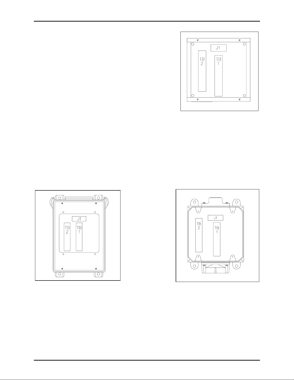
Installation
Indoor Enclosure (Model 12586-002)
1. Remove and discard the harness a ssembly (TB1), the
connector (J1), and the a ssociated hardware. See Figure 1.
OTE: Do not remove TB2 .
N
2. Ins tall the h arness assemb l y pla te by alig n i n g the p l at e wi th th e
holes used to mount the previous TB1. Secure the assembly
using the 2 screws included in the kit.
Weatherproof Enclosures (Models 12586-003
and 12586-004)
1. Remove the label on the front c over of the enclos ure, and discard it.
2. Remove and disc ard the har ness a ssembly (TB1), the connector (J1), and t he associat ed hardware. See
Figure 2 a nd Figure 3.
OTE: Do not remove TB2 .
N
3. Ins ta l l the harn ess assembly plate b y alig n i n g the p l at e wi th t he h o l es used to mount the p revious TB1.
Secur e the a ssemb l y usi ng the 2 screws in cluded i n the kit.
Figure 1. Indoor Enc l osur e
Figure 2. W eather proof Enclosu re
Glas s Reinfor c ed Polyester
\\s_eng\gtc proddoc s \ s tandard ioms - current release\ 42003 k it m anuals \42003-137a.doc
2/97
Figure 3. W eather proof Enclosu re
Cast Aluminum
Page 3

Warranty
Equipment. GAI-Tronics warrants for a period of one (1) year from the date of shipment, that any
GAI-Tronics equipment supplied hereunder shall be free of defects in material and workmanship, shall
comply with the then-current product specifications and product literature, and if applicable, shall be fit
for the purpose specified in the agreed-upon quotation or proposal document. If (a) Seller’s goods prove
to be defective in workmanship and/or material under normal and proper usage, or unfit for the purpose
specified and agreed upon, and (b) Buyer’s claim is made within the warranty period set forth above,
Buyer may return such goods to GAI-Tronics’ nearest depot repair facility, freight prepaid, at which time
they will be repaired or replaced, at Seller’s option, without charge to Buyer. Repair or replacement shall
be Buyer’s sole and exclusive remedy. The warranty period on any repaired or replacement equipment
shall be the greater of the ninety (90) day repair warranty or one (1) year from the date the original
equipment was shipped. In no event shall GAI-Tronics warranty obligations with respect to equipment
exceed 100% of the total cost of the equipment supplied hereunder. Buyer may also be entitled to the
manufacturer’s warranty on any third-party goods supplied by GAI-Tronics hereunder. The applicability
of any such third-party warranty will be determined by GAI-Tronics.
Services. Any services GAI-Tronics provides hereunder, whether directly or through subcontractors,
shall be performed in accordance with the standard of care with which such services are normally
provided in the industry. If the services fail to meet the applicable industry standard, GAI-Tronics will
re-perform such services at no cost to buyer to correct said deficiency to Company's satisfaction provided
any and all issues are identified prior to the demobilization of the Contractor’s personnel from the work
site. Re-performance of services shall be Buyer’s sole and exclusive remedy, and in no event shall GAITronics warranty obligations with respect to services exceed 100% of the total cost of the services
provided hereunder.
Warranty Periods. Every claim by Buyer alleging a defect in the goods and/or services provided
hereunder shall be deemed waived unless such claim is made in writing within the applicable warranty
periods as set forth above. Provided, however, that if the defect complained of is latent and not
discoverable within the above warranty periods, every claim arising on account of such latent defect shall
be deemed waived unless it is made in writing within a reasonable time after such latent defect is or
should have been discovered by Buyer.
Limitations / Exclusions. The warranties herein shall not apply to, and GAI-Tronics shall not be
responsible for, any damage to the goods or failure of the services supplied hereunder, to the extent
caused by Buyer’s neglect, failure to follow operational and maintenance procedures provided with the
equipment, or the use of technicians not specifically authorized by GAI-Tronics to maintain or service the
equipment. THE WARRANTIES AND REMEDIES CONTAINED HEREIN ARE IN LIEU OF AND
EXCLUDE ALL OTHER WARRANTIES AND REMEDIES, WHETHER EXPRESS OR IMPLIED BY
OPERATION OF LAW OR OTHERWISE, INCLUDING ANY WARRANTIES OF
MERCHANTABILITY OR FITNESS FOR A PARTICULAR PURPOSE.
Return Policy
If the equipment requires service, contact your Regional Service Center for a return authorization number
(RA#). Equipment should be shipped prepaid to GAI-Tronics with a return authorization number and a
purchase order number. If the equipment is under warranty, repairs or a replacement will be made in
accordance with the warranty policy set forth above. Please include a written explanation of all defects to
assist our technicians in their troubleshooting efforts.
Call 800-492-1212 (inside the USA) or 610-777-1374 (outside the USA) for help identifying the
Regional Service Center closest to you.
(Rev. 10/06)
 Loading...