

Page 1
Pub. 42004-388B
GAI-TRONICS® CORPORATION
A HUBBELL COMPANY
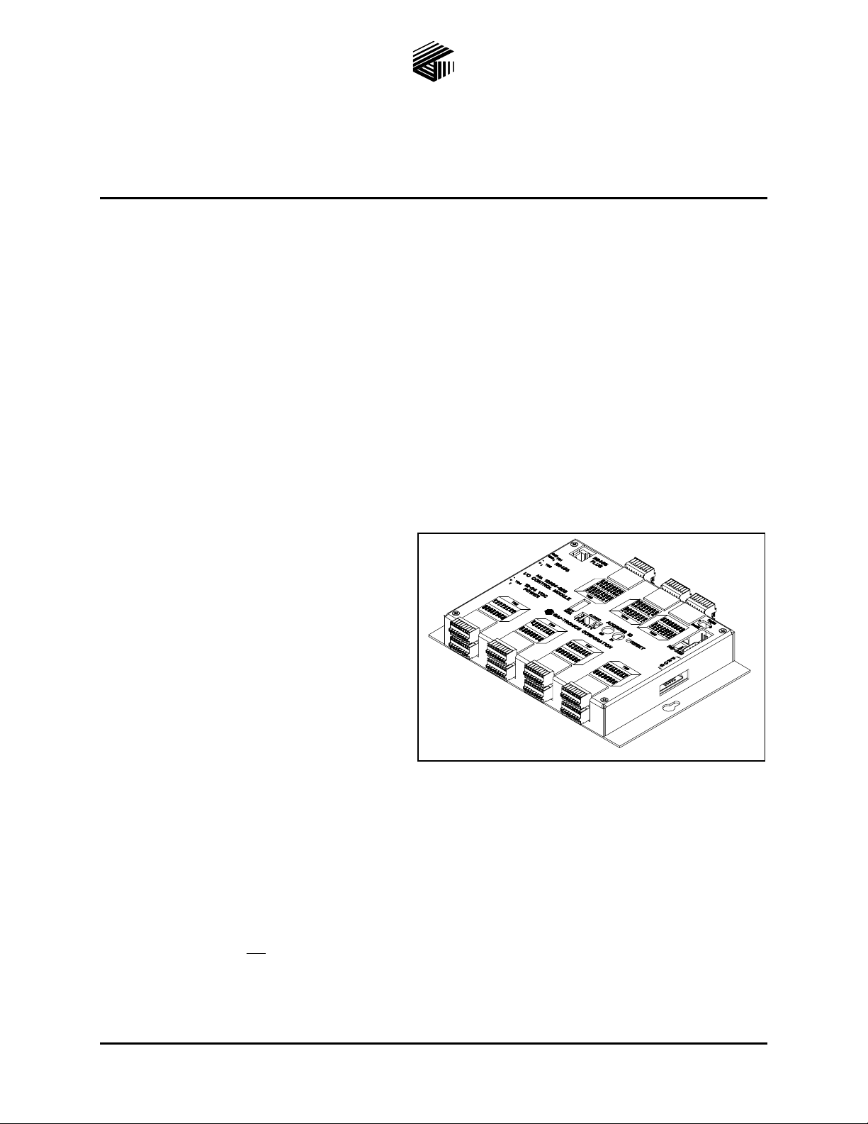
Model 12584-0 02 I/O Cont rol Module
Confidentiality Notice
This manua l is provide d sole ly as an operatio nal, installation, and ma inte nance guide and conta ins
sensitive business and t e chnical informatio n tha t is confidentia l and pr opri et ary to GAI- Tronics.
GAI-Tronics retains all intellectual property and other rights in or to the information contained herein,
and such information may only be used in connection with the operation of your GAI-Tronics product or
system. This manu al may not be dis clos e d in any form, in whole or in pa rt, direct ly or i ndir ectly, to a ny
third pa r ty.
General Information
The Model 12584-002 I/O Control Module is designed to monitor contact closure devices connected to its
input, and to turn devices on or off that are connected to its output. It operates as a slave device reporting
to a syste m ma ster controller via a seri al data line conn e c tion. The ma ster c ontr oller is programmed to
recognize the I/O Control Module and process the data information received from it.
Typically, the system master controller is a
computer or a GAI-Tronics Model 10959
Series Audio Messenger Interface (AMI). In
special applications, the system master
control ler can be another I/O Control Mo dule
that is reprogrammed with custom software.
In general, the Model 12584-002 I/O Control
Module provides the following features:
Digital Inpu t Monitori ng
The I/O Control Module can monitor up to 32
voltage-free contact inputs. The contacts can
be normally open or closed. Additionally, they
can be momentary or maintained type
activation. The programming of the system
master controller defines how each input is activated. Each input is individually programmed for the type
of activation switch and the resulting event.
Analo g Inpu t Monit oring
The I/O Control Module monitors up to eight analog voltage inputs from 0 to +5 V dc. Each input is
individually programmed to activate on a pre-programmed voltage threshold level.
Figure 1. Model 12584-002 I/O Control Module
OTE: This feature is not available when an AMI is acting as the master controller device.
N
GAI-Tronics Corporation P.O. Box 1060, Readi ng, PA 19607-1060 USA
610-777-1374 800-492-1212 Fax: 610-796-5954
ISIT WWW.GAI-TRONICS.COM FOR PRODUCT LITERATURE AND MANUALS
V
Page 2

Pub. 42004-388B
Model 12584-002 I/O Control Module Page: 2 of 15
Outpu t Control
The module provides up to 32 open collector control outputs for activating devices such as relays,
indicators, or other on/off devices. The outputs can be active high (off) or active low (on). Additionally,
they can be momentary (pulsed) or maintained type activation. The programming of the system master
controller defines how the outputs are activated. Each output is individually programmed to activate
during a cert ain system event.
Accessory D evice to the GAI-Tronic s AMI
There ar e two ways the devic e can be u se d with the AMI:
• Input/output exte nsion module - This application provides 32 additional switch inputs to the AMI
that can be programmed for alarm activation, alarm reset, muting, or telephone interface control
switches.
• Serial dat a alarm control - This application allows the system master controller to activate and reset
alarms on the AMI from a remote location without using contact closure inputs wired directly to the
AMI.
Each allocation requires a unique data connection to the AMI. Refer to the Installation section for wiring
diagrams.
Data Line Selecti on and Settings
The Model 12584-002 I/O Control Module supports both RS485 and RS232 data connections. The
RJ232 connection is accessed from a male DB-9 connector. There are two different RS485 data
connections. RS485 #1 is accessed from terminal block TB1 and TB2, and RS485 #2 is accessed on an
RJ45 receptacle .
• Data connecti o n to system master controller must be ma d e using either the RS4 8 5 #1 da ta connection
OR the RS232 data connection. Both cannot be used simultaneously.
A 3-position jumper (J6) selects either RS232 or RS485 #1 data communication.
- Shor t pins 1 and 2 to sel e c t RS485 data on TB2.
- Short pins 2 and 3 to select RS232 data on DB9 connector.
RS485 #1 data connection is made to terminal blocks TB1 and TB2. Refer to Table 7 and Table 8 in
the Installation section of this manual for data line connection details.
RS232 data connection is made to the male DB-9 connector. A null-modem cable should be used for
connection to the master controlling device.
• The RJ45 receptacle connection is used exclusively for serial data control of the AMI as mentioned
above. Refer to Table 9 in the Installation section of this manual for data line connection details. Do
not use this data connection for the system master controller.
After selecting the data line type, there are several other switches on the I/O Control Module that must be
set to the proper data format to communicate with the controlling device. Each switch is labeled on the
module case. The following sections describe each switch in detail.
\\s_eng\gtc proddoc s \st andard iom s - current release\42004 instr. manuals \ 42004-388b. doc
04/07
Page 3

Pub. 42004-388B
Model 12584-002 I/O Control Module Page: 3 of 15
Address S witches S1 a nd S2
S1 an S2 are hexadecimal switches that are used to set the I/O Controller’s address. If the system
contains more than one I/O Controller, each device must be set with a different address. The device’s
addressing should be set in se quential ord er sta rting with address 01. Swit ch S2 sets the first digit a nd
switch S1 sets the second digit.
Example:
Address 01: S2 = 0, S1 = 1
Address 02: S2 = 0, S1 = 2
Address 03: S2 = 0, S1 = 3
OTE: After changing the board address, the RESET button must be momentarily depressed for the new
N
address to take effect.
DIP Switch S4
An 8-p osition DIP switch S 4 sets various data par amete rs and operation paramet ers of the I/O c ontr oller.
The following tables indicate each switch position and the corresponding settings/functions.
DIP switch S4 positions 1-3 set the serial data line baud rate as follows:
Table 1. DIP Switch S4 Positions 1–3: Baud Rate
Switch S4-1 Switch S4-2 Switch S4-3 Baud Rate
Closed Closed Closed 2400
Open Closed Closed 4800
Closed Open Closed 9600
Open Open Closed 19200
Closed Closed Open 38400
Open Closed Open 57600
Closed Open Open 115200
Open Open Open 115200
\\s_eng\gtc proddoc s \st andard iom s - current release\42004 instr. manuals \ 42004-388b. doc
04/07
Page 4

Pub. 42004-388B
Model 12584-002 I/O Control Module Page: 4 of 15
The DIP switch S4 positions 4-8 set the operating parameters as follows:
Table 2. DIP Switch S4 Positions 4–8: Operating Parameters
DIP Switch
Position Function
S4-4 None - not used N/A
S4-5 None - not used N/A
S4-6
Automatic input
response
S4-7 Address return
S4-8
Data fault
indication
Settings
Closed - will wait for a poll request from master controlling
device before sending an input activation data message.
Open - will automatically send a data message when an active
input is detected. The controller will NOT wait for poll request
from the master controlling device.
Closed - will NOT return the controller’s address (set by hex
switch S1 and S2) when sending a data message to the master
controlling device.
Open - will return the controller’s address (set by hex switch S1
and S2) when sending a data message to the master controlling
device.
Closed - if data communication is lost with the master controlling
device, all outputs will remain in their current state until data
communication is restored.
Open - if data communication is lost with the master controlling
device, all outputs will flash on/off.
\\s_eng\gtc proddoc s \st andard iom s - current release\42004 instr. manuals \ 42004-388b. doc
04/07
Page 5

Pub. 42004-388B
Model 12584-002 I/O Control Module Page: 5 of 15
Switch Se ttings for A MI Extender Application
Table 3. Hex Switch Settings
Hex
Switch No. Function
S1 a nd S2 Board addr es s
Settings
S1 = 1
S2 = 1
Table 4. DIP Switch S4 Settings
DIP
Switch S4 Function
Settings
S4-1 Open
S4-2 Open
S4-3
Baud rate =19.2K
Closed
S4-4 N/A
S4-5 N/A N/A
S4-6 Wait for poll requ est from master Closed
S4-7 Return address to master controller Open
S4-8 Do not signal data fault with master Closed
\\s_eng\gtc proddoc s \st andard iom s - current release\42004 instr. manuals \ 42004-388b. doc
04/07
Page 6

Pub. 42004-388B
Model 12584-002 I/O Control Module Page: 6 of 15
Switch Settings for Remote I/O Applications
When the I/ O Control Mo dule is bein g used f or re mote i nput/output contr ol or for ala rm act i vati on and
reset from a master control device, the switches must be set as follows:
Table 5. Hex Switch Settings for Serial Data Control
Hex
Switch No. Function
S1 and S2
Address - TBD by system master
controller
Settings
A unique address must be set for each I/O
control module in the system. As
determined by the system master control
device. Device addressing should be set in
sequential order starting with address 01.
Table 6. DIP S4 Switch Settings: Serial Data Control
DIP
Switch S4 Function
Settings
S4-1
S4-2
S4-3
Baud rate to be determined by system
master controller’s baud rate.
See Table 1.
Baud rate must be set to match the master
controller.
S4-4 N/A N/A
S4-5 N/A N/A
S4-6 Wait for poll requ est from master Closed
S4-7 Return address to master controller Open
S4-8 Do not signal data fault with master Closed
Reset S witc h
A smal l push-button s wit ch is prov id e d to res tart the I/ O controll er’s mic ropr ocess or. M ome ntarily press
the button to initiate the reset sequence.
\\s_eng\gtc proddoc s \st andard iom s - current release\42004 instr. manuals \ 42004-388b. doc
04/07
Page 7

Pub. 42004-388B
Model 12584-002 I/O Control Module Page: 7 of 15
Installation
Wiring
WARNING
WARNING
Do not apply power until all the connections have been wired.
Connect only to a U L-listed Class 2 power source.
Table 7. TB1 Terminal Block Assignments
Terminal Labeled Function
TB1-1 GND RS485 #1 data ground
TB1-2 GND RS485 #1 data ground
Table 8. TB2 Terminal Block Assignments
Terminal Labeled Function
TB2-1 + RS485 #1 data (+)
TB2-2 - RS485 #1 data (-)
Table 9. RJ45 Connector Pin Assignments
Pin No. Function
1 No connection
2 No connection
3 RS485 #2 data ground
4 RS485 #2 data (+)
5 RS 4 8 5 #2 data (-)
6 RS485 #2 data ground
7 No connection
8 No connection
\\s_eng\gtc proddoc s \st andard iom s - current release\42004 instr. manuals \ 42004-388b. doc
04/07
Page 8

Pub. 42004-388B
Model 12584-002 I/O Control Module Page: 8 of 15
TB10 and TB9 - Digital Output Connections
The TB10 and TB9 connectors each provide 16 digital (common ground) output connections designed to
drive externally-mounted relays or other indicating circuits. Each output can sink up to 100 mA of
current. External circuitry (relays, indicators, etc.) must be powered from an external power supply of the
same voltage used to power the I/O Control Module (12 to 24 V dc). The ground (or dc common)
terminals of the external power supply must be tied to TB4 (-).
Table 10. TB9 and TB10 Digital Output Connections
Terminal Labeled Function Specifications
O
TB10-1 to
TB10-16
TB9-1 to
TB9-16
UT-1 TO 16
UT-17 TO 32
O
Digit a l out pu t s
1-16
Digit a l out pu t s
17-32
• Active Low State - sinks 100 mA (max) to GND.
• Active High State - output floats high to source
voltage.
Figure 2. Typical digital output relay wiring
\\s_eng\gtc proddoc s \st andard iom s - current release\42004 instr. manuals \ 42004-388b. doc
04/07
Page 9

Pub. 42004-388B
Model 12584-002 I/O Control Module Page: 9 of 15
TB5, TB6, TB7, and T B8 - Digital I nput Conne ctions
The TB5, TB6, TB7 and TB8 connectors each provide connections for eight contact closure inputs.
Switches or relay contact closures are used to activate the inputs. The input contacts may be any
comb inati on of mo me ntary (pulsed) swit ches and ma intained (latch e d) switches . They can be e ither N .O.
or N.C. dry contacts rated at 5 mA minimum.
N
OTE: For the inputs to operate reliably, the cable loop resistance connecting the relay/switch contact
closures cannot exceed 200 ohms. For example, using No. 24 AWG cable, the maximum cable length for
connection of the relay/switch contact closures cannot exceed 1,500 feet. Refer to the terminal block
assignment charts and Figure 3 below.
Figure 3. Typical input switch wiring
\\s_eng\gtc proddoc s \st andard iom s - current release\42004 instr. manuals \ 42004-388b. doc
04/07
Page 10

Pub. 42004-388B
Model 12584-002 I/O Control Module Page: 10 of 15
TB11 - Anal og Input Co nnections
TB11 is used for monitor sensors or dc voltage. An industry standard for sensors is to produce a 4 to 20
milliamp (mA) output to represent a range from no signal to full scale signal, with 0 mA being an
indication of an error condition. A 250-ohm resistor will produce a 1 to 5 V dc signal when 4 to 20 mA
flows through it resulting in a signal that can be connected directly to the input, assuming it is not greater
than 5 V dc. For voltages greater than 5 V, a resistor voltage divider network must be installed to reduce
the voltage level present on the input.
Figure 4. Typical Analog Input Wiring Diagram
\\s_eng\gtc proddoc s \st andard iom s - current release\42004 instr. manuals \ 42004-388b. doc
04/07
Page 11

Pub. 42004-388B
Model 12584-002 I/O Control Module Page: 11 of 15
Figure 5. Ter mi nal Block Locatio ns
Table 11. TB5 Terminal Block Assignments
Terminal Labeled Function Specifications
TB5-1 IN-1 Activates input #1
TB5-2 IN-2 Activates input #2
TB5-3 IN-3 Activates input #3
• Short input terminal to GND if using a
Normally Open activation switch.
• Remove input terminal from GND if using a
Normally Closed activation switch.
TB5-4 IN-4 Activates input #4
TB5-5 IN-5 Activates input #5
TB5-6 IN-6 Activates input #6
TB5-7 IN-7 Activates input #7
TB5-8 IN-8 Activates input #8
TB5-9
GND Ground Ground reference for input 1-8 terminals
through
TB5-16
\\s_eng\gtc proddoc s \st andard iom s - current release\42004 instr. manuals \ 42004-388b. doc
04/07
Page 12

Pub. 42004-388B
Model 12584-002 I/O Control Module Page: 12 of 15
Table 12. TB6 Terminal Block Assignments
Terminal Labeled Function Specification
TB6-1 IN-9 Activates input #9
TB6-2 IN-10 Activates input #10
TB6-3 IN-11 Activates input #11
• Short input terminal to GND if using a
Normally Open activation switch.
• Remove input terminal from GND if using a
Normally Closed activation switch.
TB6-4 IN-12 Activates input #12
TB6-5 IN-13 Activates input #13
TB6-6 IN-14 Activates input #14
TB6-7 IN-15 Activates input #15
TB6-8 IN-16 Activates input #16
TB6-9
through
GND Ground
Ground reference for input 9-16 terminals
TB6-16
Table 13. TB7 Terminal Block Assignments
Terminal Labeled Function Specification
TB7-1 IN-17 Activates input #17
TB7-2 IN-18 Activates input #18
TB7-3 IN-19 Activates input #19
• Short input terminal to GND if using a
Normally Open activation switch.
• Remove input terminal from GND if using a
Normally Closed activation switch.
TB7-4 IN-20 Activates input #20
TB7-5 IN-21 Activates input #21
TB7-6 IN-22 Activates input #22
TB7-7 IN-23 Activates input #23
TB7-8 IN-24 Activates input #24
TB7-9
GND Ground
through
TB7-16
Ground reference for input 17-24 terminals
\\s_eng\gtc proddoc s \st andard iom s - current release\42004 instr. manuals \ 42004-388b. doc
04/07
Page 13

Pub. 42004-388B
Model 12584-002 I/O Control Module Page: 13 of 15
Table 14. TB8 Terminal Block Assignments
Terminal Labeled Function Specification
TB8-1 IN-25 Input 25
TB8-2 IN-26 Input 26
TB8-3 IN-27 Input 27
• Short input terminal to GND if using a Normally Open
activation switch.
• Remove input terminal from GND if using a Normally
Closed activation switch.
TB8-4 IN-28 Input 28
TB8-5 IN-29 Input 29
TB8-6 IN-30 Input 30
TB8-7 IN-31 Input 31
TB8-8 IN-32 Input 32
TB8-9
GND Ground Ground reference for input 25-32 terminals
through
TB8-16
TB4- P ower Connec tion s
The I/O Control Module requires a dc power supply. The dc power supply voltage must be between 12
and 24 V dc. TB4 is used for power connections. Please refer to the TB4 terminal block assignment
chart and Figure 6 below.
Figure 6. Power connections at TB4
Table 15. TB4 Terminal Block Assignments
Terminal Labeled Function
TB4-1 + Power (+) 12 to 24 V dc power supply positive terminal
TB4-2 - Power (-) 12 to 24 V dc power supply negative terminal
\\s_eng\gtc proddoc s \st andard iom s - current release\42004 instr. manuals \ 42004-388b. doc
04/07
Page 14

Pub. 42004-388B
Model 12584-002 I/O Control Module Page: 14 of 15
Figure 7. Data Connection for AMI Alar m C ontro l
Figure 8. Data Connection for AMI I/ O Exte nsion
\\s_eng\gtc proddoc s \st andard iom s - current release\42004 instr. manuals \ 42004-388b. doc
04/07
Page 15

Pub. 42004-388B
Model 12584-002 I/O Control Module Page: 15 of 15
Specification s
Power Supply Require ments
Connection to a 12 to24 V dc (UL listed) class 2 power source....................................... 3.2 A maximum*
Power consumed @ 12 V dc.................................................................................... 38.4 watts maximum*
Power consumed @ 24 V dc......................................................................................76.8 watts maximum
Auxiliary outputs....................................................Sink 100 mA maximum, per output to circuit common
and pulled up to the power input voltage
*Calculations are only accurate if a single power supply is used to power the I/O PCBA and associated
output control lines. The current draw is based on all outputs being active simultaneously and sinking
100 mA each.
Mechanical
Enclosure.................................................................Steel body and cover; black fine-textured paint finish
Mounting .............................................................................................................................. Wall or shelf
Dimensions .......................................................... 7.50 W× 5.625 D × 1.20 H inches (191 × 143 × 31 mm)
Weight .............................................................................................................................2 lbs. (0.902 kg)
Environmental
Temperature range................................................................................+32º F to +122º F (0º C to +50º C)
Replaceme nt Parts
Part Number Description
69434-001 P CBA, I/O Controller
\\s_eng\gtc proddoc s \st andard iom s - current release\42004 instr. manuals \ 42004-388b. doc
04/07
Page 16

Warranty
Equipment. GAI-Tronics warrants for a period of one (1) year from the date of shipment, that any
GAI-Tronics equipment supplied hereunder shall be free of defects in material and workmanship, shall
comply with the then-current product specifications and product literature, and if applicable, shall be fit
for the purpose specified in the agreed-upon quotation or proposal document. If (a) Seller’s goods prove
to be defective in workmanship and/or material under normal and proper usage, or unfit for the purpose
specified and agreed upon, and (b) Buyer’s claim is made within the warranty period set forth above,
Buyer may return such goods to GAI-Tronics’ nearest depot repair facility, freight prepaid, at which time
they will be repaired or replaced, at Seller’s option, without charge to Buyer. Repair or replacement shall
be Buyer’s sole and exclusive remedy. The warranty period on any repaired or replacement equipment
shall be the greater of the ninety (90) day repair warranty or one (1) year from the date the original
equipment was shipped. In no event shall GAI-Tronics warranty obligations with respect to equipment
exceed 100% of the total cost of the equipment supplied hereunder. Buyer may also be entitled to the
manufacturer’s warranty on any third-party goods supplied by GAI-Tronics hereunder. The applicability
of any such third-party warranty will be determined by GAI-Tronics.
Services. Any services GAI-Tronics provides hereunder, whether directly or through subcontractors,
shall be performed in accordance with the standard of care with which such services are normally
provided in the industry. If the services fail to meet the applicable industry standard, GAI-Tronics will
re-perform such services at no cost to buyer to correct said deficiency to Company's satisfaction provided
any and all issues are identified prior to the demobilization of the Contractor’s personnel from the work
site. Re-performance of services shall be Buyer’s sole and exclusive remedy, and in no event shall GAITronics warranty obligations with respect to services exceed 100% of the total cost of the services
provided hereunder.
Warranty Periods. Every claim by Buyer alleging a defect in the goods and/or services provided
hereunder shall be deemed waived unless such claim is made in writing within the applicable warranty
periods as set forth above. Provided, however, that if the defect complained of is latent and not
discoverable within the above warranty periods, every claim arising on account of such latent defect shall
be deemed waived unless it is made in writing within a reasonable time after such latent defect is or
should have been discovered by Buyer.
Limitations / Exclusions. The warranties herein shall not apply to, and GAI-Tronics shall not be
responsible for, any damage to the goods or failure of the services supplied hereunder, to the extent
caused by Buyer’s neglect, failure to follow operational and maintenance procedures provided with the
equipment, or the use of technicians not specifically authorized by GAI-Tronics to maintain or service the
equipment. THE WARRANTIES AND REMEDIES CONTAINED HEREIN ARE IN LIEU OF AND
EXCLUDE ALL OTHER WARRANTIES AND REMEDIES, WHETHER EXPRESS OR IMPLIED BY
OPERATION OF LAW OR OTHERWISE, INCLUDING ANY WARRANTIES OF
MERCHANTABILITY OR FITNESS FOR A PARTICULAR PURPOSE.
Return Policy
If the equipment requires service, contact your Regional Service Center for a return authorization number
(RA#). Equipment should be shipped prepaid to GAI-Tronics with a return authorization number and a
purchase order number. If the equipment is under warranty, repairs or a replacement will be made in
accordance with the warranty policy set forth above. Please include a written explanation of all defects to
assist our technicians in their troubleshooting efforts.
Call 800-492-1212 (inside the USA) or 610-777-1374 (outside the USA) for help identifying the
Regional Service Center closest to you.
(Rev. 10/06)
 Loading...