

Page 1
Pub. 42004-359B
GAI-TRONICS® CORPORATION
A HUBBELL COMPANY
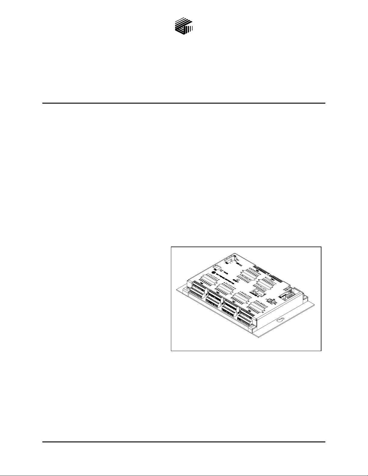
Model 12584-001
I/O Control Module
Confidentiality Notice
This manua l is provide d sole ly as an operatio nal, installation, and ma inte nance guide and conta ins
sensitive business and t e chnical informatio n tha t is confidentia l and pr opri et ary to GAI- Tronics.
GAI-Tronics retains all intellectual property and other rights in or to the information contained herein,
and such information may only be used in connection with the operation of your GAI-Tronics product or
system. This manu al may not be dis clos e d in any form, in whole or in pa rt, direct ly or i ndir ectly, to a ny
third pa r ty.
General Information
The Model 12584-001 I/O Control Module provides 32 dry contact inputs and 32 digital outputs. The
control module requires a 12 or 24 volt dc power supply. For communication and control by other
systems, the control module is equipped with two types of serial data interfaces (RS-232 and RS-485).
Data Connec tions
The I/O Control Module supports both RS485
and RS-232 data connections. A jumper is
provided to select either RS-485 or RS-232
data communi cations. The use of either the
RS-485 or RS-232 is dependent on the
application. Please refer to the
interconnecting device for data connection
details (i.e., AMI manua l).
For RS-485, the data connections are made
directly to TB2, terminals 1 and 2. Typically,
TB2-1 (+) and TB2-2 (-) connect to the
corresponding + and – terminals on the
controlling device.
For RS-232, a standard male DB-9 connector is provided. A null modem cable should be used when
connecting to the controlling device.
Figure 1. Model 12584-001 I/O Control Module
GAI-Tronics Corporation 400 E. Wyomissing Av e. Mohnton, PA 19540 USA
610-777-1374 800-492-1212 Fax: 610-796-5954
ISIT WWW.GAI-TRONICS.COM FOR PRODUCT LITERATURE AND MANUALS
V
Page 2
Pub. 42004-359B
Model 12584-001 I/O Control Module Page: 2 of 7
Installation
Wiring
WARNING
WARNING
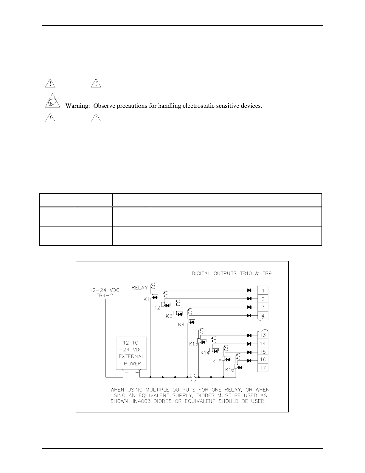
TB10 and TB9 - Digital Output Connections
Do not apply power until all the connections have been wired.
Connect only to a U L-listed Class 2 power source.
The TB10 and TB9 connectors each provide 16 digital (common ground) output connections designed to
drive externally-mounted relays or other indicating circuits. Each output can sink up to 150 mA of the
current. External circuitry (relays, indicators, etc.) must be powered from an external power supply of the
same voltage used to power the I/O Control Module (12 to 24 V dc). The ground (or dc common)
terminals of the external power supply must be tied to TB4-2.
Terminal Labeled Function Type
TB10-1 to
TB10-16
TB9-1 to
TB9-16
OUT-1 TO
16
OUT-17 TO
32
Digital
output
Digital
output
Idle = +V dc, active (low) = sink100 mA maximum
Idle = +V dc, active (low) = sink100 mA maximum
Figure 2. Typical digital output relay wiring
\\s_eng\gtc proddoc s \st andard iom s - current release\42004 instr. manuals \ 42004-359b. doc
10/08
Page 3
Pub. 42004-359B
Model 12584-001 I/O Control Module Page: 3 of 7
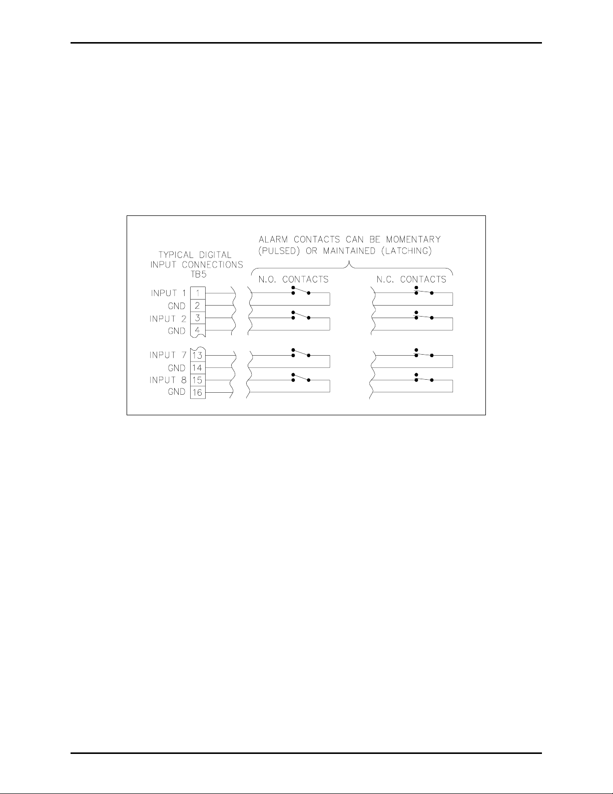
TB5, TB6, TB7, and T B8 - Digital I nput Conne ctions
The TB5, TB6, TB7 and TB8 connectors each provide connections for eight contact closure inputs.
Switches or relay contact closures are used to activate the inputs. The input contacts may be any
comb inati on of mo me ntary (pulsed) swit ches and ma intained (latch e d) switches . They can be e ither N .O.
or N.C. dry contacts rated at 5 mA minimum.
N
OTE: For the inputs to operate reliably, the cable loop resistance connecting the relay/switch contact
closures cannot exceed 200 ohms. For example, using 24 AWG cable, the maximum cable length for
connection of the relay/switch contact closures cannot exceed 1,500 feet. Refer to the terminal block
assignment charts and Figure 3 below.
Figure 3. Typical input switch wiring
\\s_eng\gtc proddoc s \st andard iom s - current release\42004 instr. manuals \ 42004-359b. doc
10/08
Page 4

Pub. 42004-359B
Model 12584-001 I/O Control Module Page: 4 of 7
Figure 4. Ter mi nal Block Locatio ns
TB5 Terminal Block Assignments
Terminal Labeled Function Type
TB5-1 IN-1 Input 1 Activates input #1
TB5-3 IN-2 Input 2 Activates input #2
TB5-5 IN-3 Input 3 Activates input #3
TB5-7 IN-4 Input 4 Activates input #4
TB5-9 IN-5 Input 5 Activates input #5
TB5-11 IN-6 Input 6 Activates input #6
TB5-13 IN-7 Input 7 Activates input #7
TB5-15 IN-8 Input 8 Activates input #8
TB5-2, 4,
GND Ground Ground reference
6, 8, 10,
12, 14, 16
\\s_eng\gtc proddoc s \st andard iom s - current release\42004 instr. manuals \ 42004-359b. doc
10/08
Page 5

Pub. 42004-359B
Model 12584-001 I/O Control Module Page: 5 of 7
TB6 Terminal Block Assignments
Terminal Labeled Function Type
TB6-1 IN-9 Input 9 Activates input #9
TB6-3 IN-10 Input 10 Activates input #10
TB6-5 IN-11 Input 11 Activates input #11
TB6-7 IN-12 Input 12 Activates input #12
TB6-9 IN-13 Input 13 Activates input #13
TB6-11 IN-14 Input 14 Activates input #14
TB6-13 IN-15 Input 15 Activates input #15
TB6-15 IN-16 Input 16 Activates input #16
TB6-2, 4,
GND Ground Ground reference
6, 8, 10,
12, 14, 16
TB7 Terminal Block Assignments
Terminal Labeled Function Type
TB7-1 IN-17 Input 17 Activates input #17
TB7-3 IN-18 Input 18 Activates input #18
TB7-5 IN-19 Input 19 Activates input #19
TB7-7 IN-20 Input 20 Activates input #20
TB7-9 IN-21 Input 21 Activates input #21
TB7-11 IN-22 Input 22 Activates input #22
TB7-13 IN-23 Input 23 Activates input #23
TB7-15 IN-24 Input 24 Activates input #24
TB7-2, 4,
GND Ground Ground reference
6, 8, 10,
12, 14, 16
\\s_eng\gtc proddoc s \st andard iom s - current release\42004 instr. manuals \ 42004-359b. doc
10/08
Page 6

Pub. 42004-359B
Model 12584-001 I/O Control Module Page: 6 of 7
TB8 Terminal Block Assignments
Terminal Labeled Function Type
TB8-1 IN-25 Input 25 Activates input #25
TB8-3 IN-26 Input 26 Activates input #26
TB8-5 IN-27 Input 27 Activates input #27
TB8-7 IN-28 Input 28 Activates input #28
TB8-9 IN-29 Input 29 Activates input #29
TB8-11 IN-30 Input 30 Activates input #30
TB8-13 IN-31 Input 31 Activates input #31
TB8-15 IN-32 Input 32 Activates input #32
TB8-2, 4,
GND Ground Ground reference
6, 8, 10,
12, 14, 16
TB4- P ower Connec tion s
The I/O Control Module requires a dc power supply. The dc power supply voltage must be between 12
and 24 V dc. TB4 is used for power connections. Please refer to the TB4 terminal block assignment
chart and Figure 5 below.
Figure 5. Power connections at TB4
Terminal Labeled Description Function
TB4-1 + Power (+) 12 to 24 V dc power supply positive terminal
TB4-2 - Power (-) 12 to 24 V dc power supply negative terminal
\\s_eng\gtc proddoc s \st andard iom s - current release\42004 instr. manuals \ 42004-359b. doc
10/08
Page 7

Pub. 42004-359B
Model 12584-001 I/O Control Module Page: 7 of 7
Specification s
Power Supply Require ments
Connection to a 12 to24 V dc (UL listed) Class 2 power source.....................................600 mA minimum
Power consumed............................................................................................................7 watts maximum
Auxiliary outputs....................................................Sink 150 mA maximum, per output to circuit common
and pulled up to the power input voltage
Mechanical
Enclosure.................................................................Steel body and cover; black fine-textured paint finish
Mounting .............................................................................................................................. Wall or shelf
Dimensions ..........................................................7.50 W× 5.625 D × 1.02 H inches (191 × 143 × 26 mm)
Weight ............................................................................................................................ 2 lbs. (0.902 kg)
Environmental
Temperature range................................................................................+32º F to +122º F (0º C to +50º C)
Replaceme nt Parts
Part Number Description
69407-002 PCBA, I/O Controller
\\s_eng\gtc proddoc s \st andard iom s - current release\42004 instr. manuals \ 42004-359b. doc
10/08
 Loading...