

Page 1

Pub. 42004-600L2C
GAI-TRONICS® CORPORATION
A HUBBELL COMPANY
Model 12580-001
Amplifier Distribution/Monitor Module
Confidential ity Notice
This manual is provided solely as an operational, installation, and maintenance guide and contains
sensitive business and technical information that is confidential and proprietary to GAI-Tronics.
GAI-Tronics retains all intellectual property and other rights in or to the information contained herein,
and such information may only be used in connection with the operation of your GAI-Tronics product or
system. This manual may not be disclosed in any form, in whole or in part, directly or indirectly, to any
third party.
Introduction
This document discusses installing, operating, and maintaining the 12580-001 Amplifier Distribution/
Monitor Module (ADM), which provides the following features:
• Distributes audio to central amplifiers
• Verifies the integrity of speaker loops
• Monitors amplifier failure contacts
• Communicates with the Master Control Unit
How to Use the Assembly
This section describes applications for the Amplifier Distribution/Monitor Module, its hardware
configuration, block diagram, interfaces, and installation. Because this assembly is controlled by a 69254
Series or 69440 Series Master Control Unit (MCU) and is set up in the MCU’s configuration software,
there are no operating controls or software configuration for the ADM. Refer to the MCU Configuration
details in your system manual for all operation information.
Application
The Amplifier Distribution/Monitor Module is used to distribute audio to up to six central amplifiers. It
is also used to verify the integrity of the related speaker loops and to monitor up to six amplifier failure
contacts, reporting their status to the MCU. The ADM’s speaker loop inputs allow it to detect various
fault conditions on any of up to six speaker loops. These fault conditions include ground faults, cable
breaks*, wire-to-wire short circuits*, and amplifier failures.
GAI-Tronics Corporation 400 E. Wyomissing Ave. Mohnton, PA 19540 USA
610-777-1374 800-492-1212 Fax: 610-796-5954
V
ISIT WWW.GAI-TRONICS.COM FOR PRODUCT LITERATURE AND MANUALS
Page 2
Pub. 42004-600L2C
Model 12580-001 Amplifier Distribution/Monitor Module Page: 2 of 17
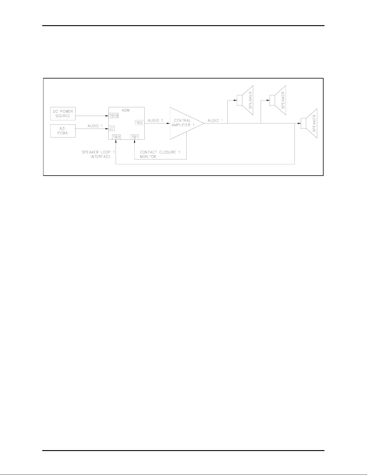
The ADM’s contact closure inputs are typically used to monitor the amplifier failure contacts of the
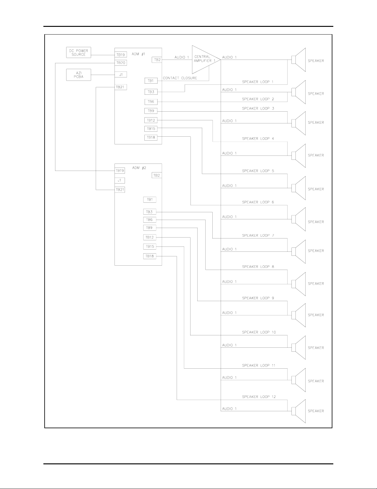
central amplifiers to determine amplifier failure. Figure 1 illustrates a typical application for one paging
zone. Figure 2 illustrates an alternate application for one central amplifier and twelve speaker loops.
OTE: (*) indicates that fault detection occurs only while the associated amplifier is not in use.
N
Figure 1. Single Page Zone - Typical Application
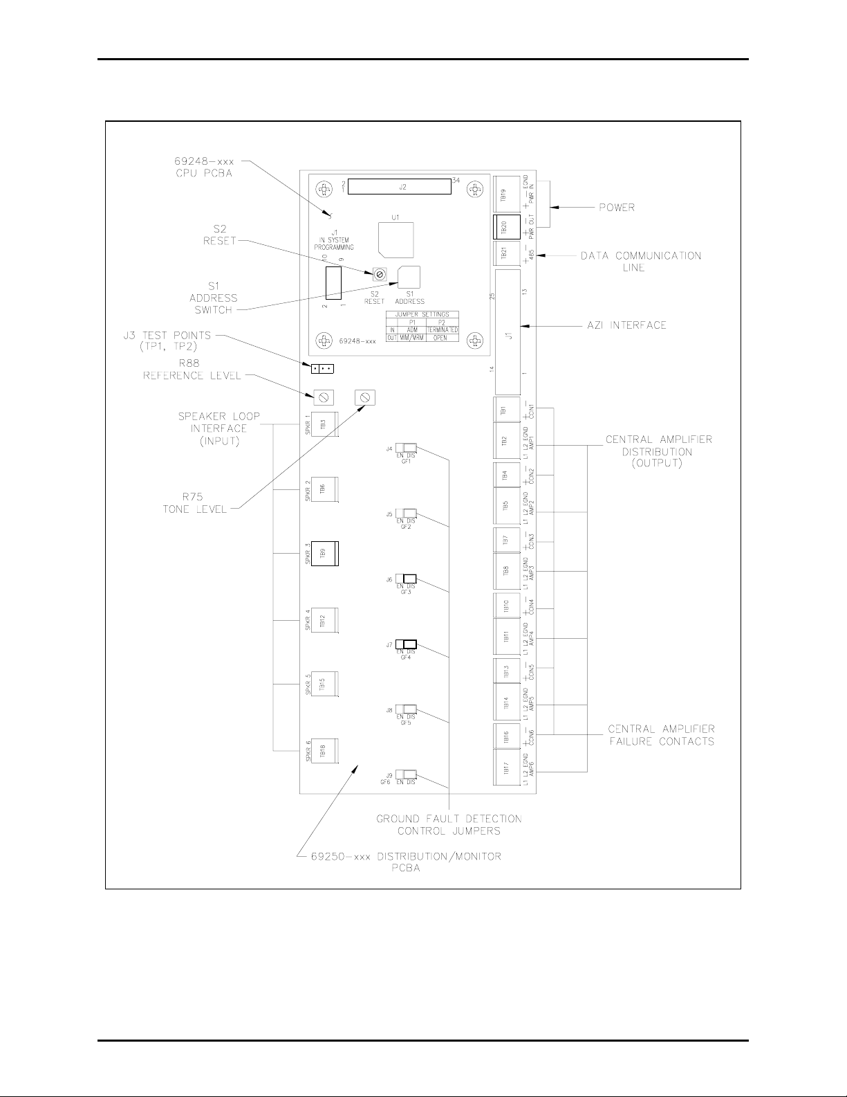
The ADM is comprised of two subassemblies: the 69250-xxx Distribution/Monitor printed circuit board
assembly (PCBA) and the 69248-xxx Central Processing Unit (CPU) PCBA. The ADM mounts in a
Snaptrack™, a grooved plastic channel that allows a PCBA to securely ‘snap’ into place. The
Snaptrack™ provides flexible installation because it may be installed in an equipment rack wherever it is
convenient.
The ADM communicates with the MCU via the CPU PCBA over a bi-directional RS-485 link. The CPU
PCBA monitors the status of the module’s contact clo sure inputs and speaker loop inputs and reports
them to the MCU via this communication link.
The MCU periodically interrogates the ADM to determine its status. The MCU identifies a particular
module on this RS-485 link by its address. (The ADM’s module address is set by rotary hex switch S1,
located on the CPU PCBA.)
f:\standard ioms - current release\42004 instr. manuals\42004-600l2c.doc
10/11
Page 3
Pub. 42004-600L2C
Model 12580-001 Amplifier Distribution/Monitor Module Page: 3 of 17
Figure 2. Single Amplifier with 12 Speaker Loops - Alternate Application
f:\standard ioms - current release\42004 instr. manuals\42004-600l2c.doc
10/11
Page 4
Pub. 42004-600L2C
Model 12580-001 Amplifier Distribution/Monitor Module Page: 4 of 17
Hardware Configuration
Figure 3. Hardware Configuration
f:\standard ioms - current release\42004 instr. manuals\42004-600l2c.doc
10/11
Page 5
Pub. 42004-600L2C
Model 12580-001 Amplifier Distribution/Monitor Module Page: 5 of 17
Interfaces
The Model 12580-001 Amplifier Distribution/Monitor Module provides a number of external interfaces,
all of which are located on the Distribution/Monitor PCBA.
Power
The ADM uses 3-position terminal block TB19 (labeled PWR
IN) to deliver dc power (12 V dc) to the
PCBAs and to provide an earth ground connection for them. Two-position terminal block TB20 (labe led
OUT) brings out the dc power from TB19, allowing additional Snaptrack™ modules to receive
PWR
power. The pinout for TB19
WARNING
is shown in Table 1 and the pinout for TB20 is shown in Table 2.
Incorrect connection of the power source to TB19 or TB20 may cause damage to this assembly.
Table 1. Power Input - TB19 Pinout
Pin No. Function Description
1
2
3
PWR
PWR
PWR
IN +
IN −
IN EGND
Connects to the positive lead of the power supply (input)
Connects to the negative (ground) lead of the power supply (input)
Connects to earth ground (input)
Table 2. Power Output - TB20 Pinout
Pin No. Function Description
1
PWR
OUT +
Connects the positive lead of the power supply to other Snaptrack™
modules (output)
2
PWR
OUT −
Connects the negative (ground) lead of the power supply to other
Snaptrack™ modules (output)
AZI Interface
DB-25 style connector J1 interfaces the Amplifier Zone Interface (AZI) PCBA to the ADM. J1 connects
the six central amplifier input lines, the RS-485 data communication line, and earth ground of the AZI
PCBA to the ADM. The six central amplifier input lines are connected to the following 3-position
terminal blocks: TB2, TB5, TB8, TB11, TB14, and TB17.
f:\standard ioms - current release\42004 instr. manuals\42004-600l2c.doc
10/11
Page 6

Pub. 42004-600L2C
Model 12580-001 Amplifier Distribution/Monitor Module Page: 6 of 17
The RS-485 data communications line is connected to J2 (to interface with the CPU PCBA) and to 2position terminal block, TB21. Earth ground is connected to TB19 pin 3. The pinout for AZI interface
connector J1 is shown in Table 3.
Table 3. AZI Interface J1 Pinout
Pin
No. Function
RS485+
1
Passes the positive leg of the
Description
Pin
No. Function
RS485−
14
RS-485 interface from the AZI
PCBA to TB21 (
485 +) (I/O)
2 Not used 15 Not used
3 Not used 16 Not used
4 Not used 17 Not used
5
AMP1_L1
Passes one leg of audio input
18
AMP1_L2
for central amplifier 1 from the
AZI PCBA to TB2 (
AMP1 L1)
(input)
6
AMP2_L1
Passes one leg of audio input
19
AMP2_L2
for central amplifier 2 from the
AZI PCBA to TB5 (
AMP2 L1)
(input)
7
AMP3_L1
Passes one leg of audio input
20
AMP3_L2
for central amplifier 3 from the
AZI PCBA to TB8 (
AMP3 L1)
(input)
Description
Passes the negative leg of the
RS-485 interface from the
AZI PCBA to TB21 (
485 −)
(I/O)
Passes the other leg of audio
input for central amplifier 1
from the AZI PCBA to TB2
AMP1 L2) (input)
(
Passes the other leg of audio
input for central amplifier 2
from the AZI PCBA to TB5
(AMP2 L2) (input)
Passes the other leg of audio
input for central amplifier 3
from the AZI PCBA to TB8
AMP3 L2) (input)
(
8
9
10
AMP4_L1
AMP5_L1
AMP6_L1
Passes one leg of audio input
for central amplifier 4 from the
AZI PCBA to TB11 (
AMP4 L1)
(input)
Passes one leg of audio input
for central amplifier 5 from the
AZI PCBA to TB14 (
AMP5 L1)
(input)
Passes one leg of audio input
for central amplifier 6 from the
AZI PCBA to TB17 (
AMP6 L1)
(input)
21
22
23
AMP4_L2
AMP5_L2
AMP6_L2
Passes the other leg of audio
input for central amplifier 4
from the AZI PCBA to TB11
(AMP4 L2) (input)
Passes the other leg of audio
input for central amplifier 5
from the AZI PCBA to TB14
AMP5 L2) (input)
(
Passes the other leg of audio
input for central amplifier 6
from the AZI PCBA to TB17
AMP6 L2) (input)
(
11 not used 24 not used
12 not used 25 not used
13
EGND
Passes earth ground to the AZI
PCBA (output)
NOTE: Connector J1 of the ADM is connected to the AZI PCBA via a DB25 cable assembly. This
cable assembly is not included with the ADM and must be purchased separately.
f:\standard ioms - current release\42004 instr. manuals\42004-600l2c.doc
10/11
Page 7

Pub. 42004-600L2C
Model 12580-001 Amplifier Distribution/Monitor Module Page: 7 of 17
Data Communication Line
Terminal block, TB21 is provided to enable the RS-485 signal to be daisy-chained to additional
Snaptrack™ modules. The pinout for the data communications line is shown in Table 4.
Table 4. Data Communications Line - TB21 Pinout
Pin
No. Function
1
485
+
Daisy-chains the positive leg of the RS-485 interface to other Snaptrack™ modules
Description
(I/O)
2
485
−
Daisy-chains the negative leg of the RS-485 interface to other Snaptrack™ modules
(I/O)
NOTE: The conductors terminated on this terminal block should be a twisted pair.
Central Amplifier Audio Distribution
Terminal blocks TB2, TB5, TB8, TB11, TB14, and TB17are provided to connect audio from the AZI to
the six central amplifier inputs. The audio signals are differential, so a 2-connductor cable is required for
each input. An additional termination point (EGND) has been provided for an earth ground connection.
The pinout for TB2, TB5, TB8, TB11, TB14, and TB17 is shown in Table 5.
Table 5. Central Amplifier Audio Distribution - TB2, TB5, TB8, TB11, TB14, and TB17 Pinout
Pin
No. Function
Description
1
2
3
AMP
AMP
AMP
L1
L2
EGND
Connects one leg of audio to a central amplifier’s input (output)
Connects the other leg of audio to a central amplifier’s input (output)
Connects earth ground to a central amplifier (output)
NOTE: For optimum audio quality, the conductors terminated on pins 1 and 2 of these terminal blocks
should be twisted pairs.
f:\standard ioms - current release\42004 instr. manuals\42004-600l2c.doc
10/11
Page 8

Pub. 42004-600L2C
Model 12580-001 Amplifier Distribution/Monitor Module Page: 8 of 17
Central Amplifier Failure Inputs
The ADM contains six 2-position terminal blocks (TB1, TB4, TB7, TB10, TB13, and TB16) to receive
central amplifier failure contacts. A normally open or normally closed dry contact closure input is
provided for each amplifier. The pinout for the central amplifier failure inputs is shown in Table 6.
Table 6. Central Amplifier Failure Inputs - TB1, TB4, TB7, TB10, TB13, and TB16 Pinouts
Pin
No. Function
1
2
CCIN
CCIN
+
−
Connects to one leg of a central amplifier’s contact closure (input)
Connects to the other leg of a central amplifier’s contact closure (input)
Description
Speaker Loop Interfaces
The ADM contains six 2-position terminal blocks (TB3, TB6, TB9, TB12, TB15, and TB18) to enable
termination of the six central am pli fier s peak er loops. The ADM monitors the speaker loops for ground
faults, cable breaks*, wire-to-wire shorts*, and amplifier failures. The pinout for TB3, TB6, TB9, TB12,
TB15, and TB18
OTES:
N
is shown in Table 7.
• (*) indicates that fault detection occurs only while the associated amplifier is not in use.
• Only one voltage type (25 V, 70 V, etc.) may be supervised at a time.
Table 7. Speaker Loop Interfaces TB3, TB6, TB9, TB12, TB15, and TB18 Pinouts
Pin
No. Function
Description
1
2
SPKR
SPKR
Connects to one leg of a central amplifier’s speaker loop (input)
Connects to the other leg of a central amplifier’s speaker loop (input)
NOTE: The conductors terminated on these terminal blocks should be twisted pairs. These connections
are not polarity-sensitive.
f:\standard ioms - current release\42004 instr. manuals\42004-600l2c.doc
10/11
Page 9

Pub. 42004-600L2C
Model 12580-001 Amplifier Distribution/Monitor Module Page: 9 of 17
Installation
This section contains installation instructions for the Amplifier Distribution/Monitor Module. Notify
plant personnel of a system shutdown prior to servicing the unit.
Precautions
Adhere to all warnings and all safety and operating instructions on the unit and in this manual.
WARNING
Disconnect power to the ADM and central amplifiers before installing, removing, or servicing the
module.
Do not touch bare wires.
Avoid servicing the unit during electrical storms.
f:\standard ioms - current release\42004 instr. manuals\42004-600l2c.doc
10/11
Page 10

Pub. 42004-600L2C
Model 12580-001 Amplifier Distribution/Monitor Module Page: 10 of 17
Hardware Configuration
Before installing a new ADM, set S1 on the CPU PCBA to the module address and set the jumper
settings (J4-J9) as shown in the system manual. Valid address settings are (5 to E). Jumper settings
(J4–J9) allow ground fault detection to be enabled or disabled. See Table 8 for the jumper setting details.
OTES:
N
• To ensure proper termination, crimp a ferrule on the end of any conductor that is to be terminated on
a terminal block. The size of the ferrule depends on the size of the conductor used and may be
obtained from suppliers such as Phoenix, Altec, or Weidmuller. The terminals accept a maximum
conductor size of No. 12 AWG and a minimum conductor size of No. 28 AWG.
• Ground fault detection can be enabled only when one speaker loop from each amplifier is being
monitored.
Table 8. Ground Fault Control Jumpers J4 through J9
Reference
Designator
J4
(GF1)
J5
(GF2)
J6
(GF3)
J7
(GF4)
J8
(GF5)
J9
(GF6)
Speaker loop 1 ground
fault detection control
Speaker loop 2 ground
fault detection control
Speaker loop 3 ground
fault detection control
Speaker loop 4 ground
fault detection control
Speaker loop 5 ground
fault detection control
Speaker loop 6 ground
fault detection control
Description
NOTE: (*) indicates the factory default setting.
Valid Settings
• Pins 1 and 2 (EN) shorted: enabled
• Pins 2 and 3 (DIS) shorted: disabled*
• Pins 1 and 2 (EN) shorted: enabled
• Pins 2 and 3 (DIS) shorted: disabled*
• Pins 1 and 2 (EN) shorted: enabled
• Pins 2 and 3 (DIS) shorted: disabled*
• Pins 1 and 2 (EN) shorted: enabled
• Pins 2 and 3 (DIS) shorted: disabled*
• Pins 1 and 2 (EN) shorted: enabled
• Pins 2 and 3 (DIS) shorted: disabled*
• Pins 1 and 2 (EN) shorted: enabled
• Pins 2 and 3 (DIS) shorted: disabled*
f:\standard ioms - current release\42004 instr. manuals\42004-600l2c.doc
10/11
Page 11

Pub. 42004-600L2C
Model 12580-001 Amplifier Distribution/Monitor Module Page: 11 of 17
Mounting
To install the module into the Snaptrack ™, slide ei the r the right or left edge of the module into the top
groove on the track. On the opposite edge of the module, press firmly on the top and bottom corners of
the module until they snap into the groove. Carefully press from each corner toward the center and
simultaneously snap the edge firmly into place.
Power
After installing the ADM in the Snaptrack™, bring 12 V dc power from the auxiliary power supply to
(labeled PWR IN). Connect the positive leg to terminal 1 (+) and the negative or return leg to
TB19
terminal 2 (−). Connect earth ground to terminal 3 (EGND). TB20
with TB19
so that power may be distributed to additional Snaptrack™ modules.
(labeled PWR OUT) is paralleled
WARNING
Incorrect connection of the power source to TB19 or TB20 may cause damage to this assembly.
N
OTES:
• Although power may be daisy-chained between Snaptrack™ modules, the preferred method of
delivering power to these modules is to provide a dedicated cable run from the power supply to each
module.
• The auxiliary power supply is not part of the 10457 Series Card Rack Assembly nor does the card
rack assembly power supply provide power to Snaptrack™ modules. An additional power supply
must be included in the cabinet to support these modules.
• For proper operation, connect the auxiliary power supply return leg to earth ground at the auxiliary
power supply.
• The ground reference for this assembly must be identical to that of the card rack assembly.
• The ADM does not provide any current-limiting for input power. An external fuse of the Slo-Blo
variety, with the appropriate voltage and current ratings, should be provided.
®
f:\standard ioms - current release\42004 instr. manuals\42004-600l2c.doc
10/11
Page 12

Pub. 42004-600L2C
Model 12580-001 Amplifier Distribution/Monitor Module Page: 12 of 17
AZI Interface
Connect a DB25 cable assembly (sold separately) from the AZI PCBA to the J1 connector of the ADM.
J1 connects the six central amplifier input lines, the RS-485 data communication line, and earth ground of
the AZI PCBA to the ADM.
Data Communication Line
Terminal block TB21 has been provided to distribute the RS-485 data communication line to additional
Snaptrack™ modules. If there are no additional Snaptrack™ modules, connect a 150-ohm, ½ watt
terminating resistor (sold separately) across TB21 of the 69250-xxx, or install a jumper across the pins of
P2 on the 69248-xxx CPU PCBA.
CAUTION
The RS-485 line is polarity-sensitive. Be sure to maintain circuit polarity throughout installation.
OTES:
N
1. The conductor terminated on TB21
should be a twisted pair.
2. Only one termination is to be applied to an RS-485 circuit - either a 150-ohm resistor across TB21, or
a jumper across the pins of P2.
Central Amplifier Audio Distribution
Connect terminal blocks TB2, TB5, TB8, TB11, TB14, and TB17
OTE: For optimum audio quality, the conductors terminated on pins 1 and 2 of TB2, TB5, TB8, TB11,
N
to the associated central amplifiers.
TB14, and TB17 should be twisted pairs.
Central Amplifier Failure Inputs
Connect the central amplifier failure contacts to the ADM at terminal block connectors TB1, TB4, TB7,
TB10, TB13, and TB16. These dry contact closures ty pically orig ina te from the associa ted cen tra l
amplifiers.
f:\standard ioms - current release\42004 instr. manuals\42004-600l2c.doc
10/11
Page 13

Pub. 42004-600L2C
Model 12580-001 Amplifier Distribution/Monitor Module Page: 13 of 17
Speaker Loop Return Lines
Terminate the central am plifie r speaker loops to be monitored by the ADM on connectors TB3, TB6,
TB9, TB12, TB15, and TB18. Typically, this connection is made to the last speaker on the circuit so
that the entire loop is monitored. These connections are not polarity-sensitive.
OTE: The conductors terminated on TB3, TB6, TB9, TB12, TB15, and TB18 should be twisted pairs.
N
Table 9. Circuit Relationships
Function →
Ckt. No. ↓
1 TB2-1 (AMP1 L1)
2 TB5-1 (AMP2 L1)
3 TB8-1 (AMP3 L1)
4 TB11-1 (AMP4 L1)
5 TB14-1 (AMP5 L1)
6 TB17-1 (AMP6 L1)
Central Amplifier
Audio Distribution
TB2-2 (AMP1
TB5-2 (AMP2
TB8-2 (AMP3
TB11-2 (AMP4
TB14-2 (AMP5
TB17-2 (AMP6
L2)
L2)
L2)
L2)
L2)
L2)
Speaker Loop
Interfaces
TB3 (SPKR
TB6 (SPKR
TB9 (SPKR
1) J4 (GF1) TB1 (CCIN1)
2) J5 (GF2) TB4 (CCIN2)
3) J6 (GF3) TB7 (CCIN3)
TB12 (SPKR
TB15 (SPKR
TB18 (SPKR
Ground Fault
Detection Control
4) J7 (GF4) TB10 (CCIN4)
5) J8 (GF5) TB13 (CCIN5)
6) J9 (GF6) TB16 (CCIN6)
Central Amplifier
Failure Contact
Table 9 shows the relationship between the connectors and headers for each of the six circuits the ADM
supports. It includes the component’s desig na tion and the labe l prin ted on the Distribu ti on/ Mon ito r
PCBA, where applicable.
For example: audio for circuit 1’s am plifier input is passed from the AZI PCBA to terminal block TB2
(labeled AMP1
SPKR
1) and it includes ground fault detection control via header J4 (l abe led GF1). The related contact
closure input is via TB1
L1 and AMP1 L2). The speaker loop return line for this circuit is via TB3 (la bel ed
(labeled CCIN1).
After all terminations have been made, apply power to the equipment, and adjust referenc e lev el
tone level
f:\standard ioms - current release\42004 instr. manuals\42004-600l2c.doc
10/11
R75 as described in the “Maintenance” section.
R88 and
Page 14

Pub. 42004-600L2C
Model 12580-001 Amplifier Distribution/Monitor Module Page: 14 of 17
How to Diagnose Assembly Faults
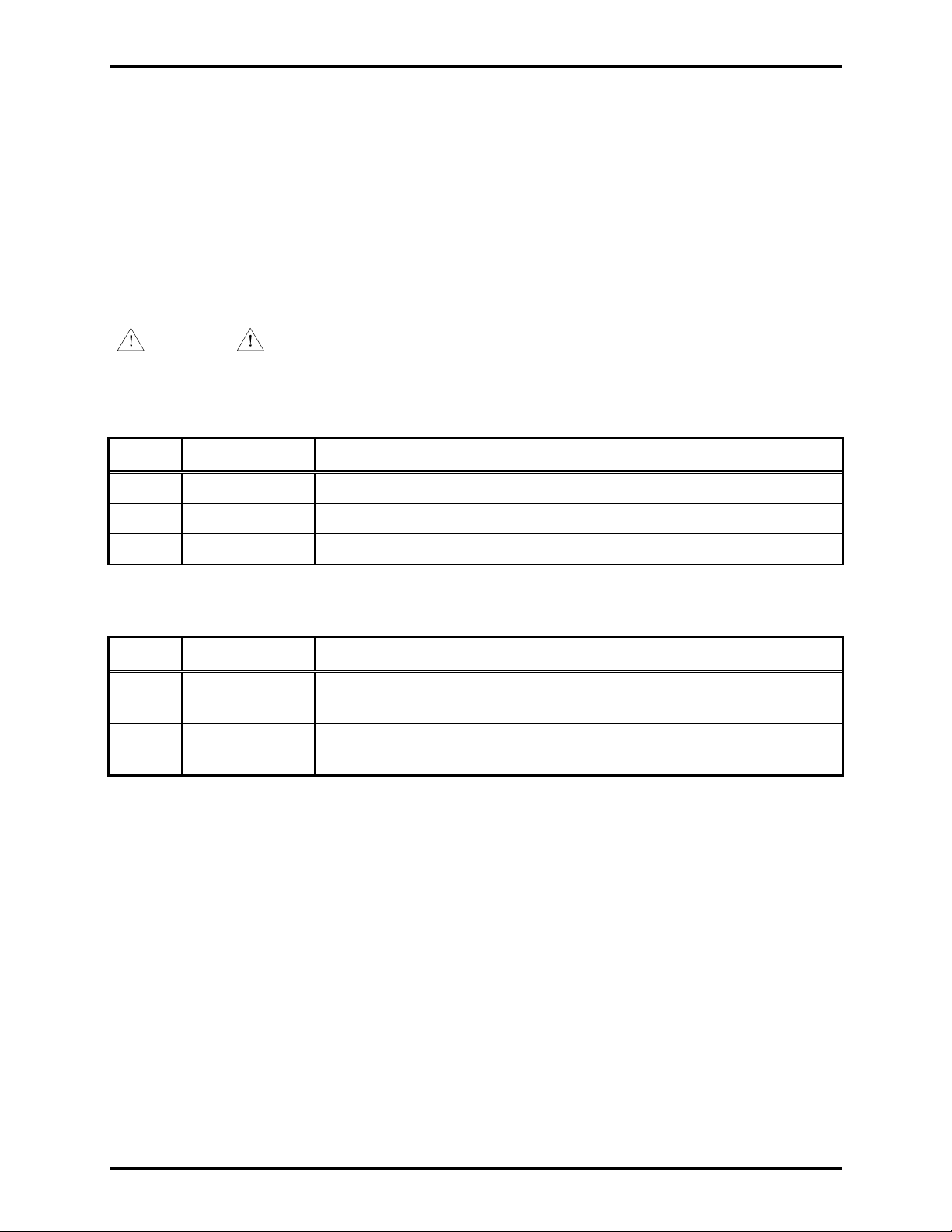
Table 10 describes possible solutions for some common problems.
Table 10. Fault Diagnosis
Problem Possible Solution
General malfunction
Ground fault detector does
not respond to ground
faults on one or more
speaker loop interfaces
• Verify that power is properly connected to TB19.
• Verify proper polarity and dc voltage range (+9 to +15 V dc) at
TB19 (PWR
IN).
• Verify that the address (S1) matches the system configuration and
the unit is enabled.
• Verify that all Snaptrack™ modules are set to a unique address.
• Verify the power supply negative terminal is connected to earth
ground.
• Verify the proper polarity of the RS-485 data line for all Snaptrack™
modules connected to this unit.
• Verify that the cable assembly is properly connected between the
ADM (on J1) and the AZI PCBA.
• Verify that the CPU PCBA is properly seated on the
Distribution/Monitor PCBA.
• Verify that the ground fault detection control header for the
corresponding speaker loop interface (refer to Table 9) is set to the
enable position (EN).
• Verify the ground fault detection is enabled in the system
configuration.
• Call for service.
Supervisory tone detector
does not respond to tone on
one or more speaker loop
• Check the input and output cabling between the central amplifier and
the ADM.
• Verify that the central am plif ier is op erat iona l.
interfaces
• Check the Tone Level
adjustment.
• Verify the speaker loop supervision is enabled in the system
configuration.
• Call for service.
Central amplifier fa ilu re
contacts are not reported.
• Check cabling between the central amplifier and the ADM.
• Verify the amplifier failure contacts are enabled in the system
configuration.
• Call for service.
f:\standard ioms - current release\42004 instr. manuals\42004-600l2c.doc
10/11
R75, and Reference Level, R88 for proper
Page 15

Pub. 42004-600L2C
Model 12580-001 Amplifier Distribution/Monitor Module Page: 15 of 17
How to Maintain the Assembly
This section describes maintenance for the Amplifier Distribution/Monitor Module and lists its
specifications and replacement parts.
Maintenance
WARNING
Disconnect power to the ADM and central amplifiers before servicing.
1. Inspect and replace frayed or cracked wiring.
2. Secure/replace loose wires and spade terminals.
3. Remove corrosion from terminals.
Adjustments
The ADM contains two adjustable controls; a Reference Level adjustment, and a Tone Level adjustment.
• The Reference Level adjustment,
R88, sets a reference point (trip point). The Tone Level must exceed
the reference level to enable detection of the Superv is o ry Tone.
• The Tone Level Adjustment,
R75, controls the Supervisory Tone signal level applied to the detector.
These adjustments are set at the factory for a 70.7 V central amplifier system. Additional adjustments
may be required during installation to meet the requirements of your system. Use a straight blade
screwdriver and a dc voltmeter to make adjustments.
f:\standard ioms - current release\42004 instr. manuals\42004-600l2c.doc
10/11
Page 16

Pub. 42004-600L2C
Model 12580-001 Amplifier Distribution/Monitor Module Page: 16 of 17
Reference Level Adjustmen t
1. Set the dc voltmeter to the 20 V scale.
2. Connect the dc voltmeter between (J10 pin 2) ground and test point 2 (TP2-J10 pin 3).
3. Adjust the
R88 Reference Level to one of the following set points:
Speaker Loop
Input Voltage
Reference Level
Setting
Tone Level
Setting
10 V 50 mV 200 mV or higher
25 V 350 mV 500 mV or higher
70.7 V 1.85 V factory setting 2.0 V or higher
100 V 2.35 V 2.5 V or higher
141 V 2.35 V 2.5 V or higher
Tone Level Adjustment
1. Set the dc voltmeter to the 20 V scale.
2. Connect the dc voltmeter between ground (J10 pin 2) and test point 1 (TP1-J10 pin 1).
3. While the Supervisory Tone is active (active approximately every 90 seconds), adjust
R75 Tone
Level until the dc voltage exceeds the Reference Level by at least 150 mV dc (factory setting), or
rotate
R75 fully clockwise.
f:\standard ioms - current release\42004 instr. manuals\42004-600l2c.doc
10/11
Page 17

Pub. 42004-600L2C
Model 12580-001 Amplifier Distribution/Monitor Module Page: 17 of 17
Specification s
Electrical
Power requirements ............................................................................... +9 to +15 V dc (+12 V dc nominal)
Current draw.....................................................................48 mA (min.), 70 mA (nominal), 132 mA (max.)
Input/output.......................................................................................................................................Power in
Power out
RS-485
Six audio outputs (for use with external amplifiers)
Six contact closure inputs
Six speaker loop interfaces (for fault detection)
RS-485 termination.............................................................................On board when P2 jumper is installed
Speaker loop ground fault detection...............................................................Less than 5 kilohms to ground
Supervisory tone detect ion sens itivity ................. 10 V
Speaker loop interface maximum voltage................................................................................ 141 V
Speaker loop input impedance.................................................................................20 kilohms min. (1 kHz)
Contact closure on-resistance....................................................................................................10 ohms max.
min. @ speaker loop interface (fin = 19.394 kHz)
RMS
RMS
max.
Terminals
Minimum conductor size..........................................................................................No. 28 AWG (0.5 mm
Maximum conductor size..........................................................................................No. 12 AWG (3.0 mm
2
2
Environmental
Temperature range (operating/storage).................................................. +32° F to +122° F (0° C to +50° C)
Humidity............................................................................95% non-condensing relative humidity (+50° C)
Mechanical
Unit dimensions........................................................4.0 H × 10.5 W × 1.50 D inches (102 × 267 × 38 mm)
Unit weight.......................................................................................................................1.0 lb. (454 g) max.
Approval
CE Mark
Replac ement Parts
Model Number Description
69248-xxx CPU PCBA
)
)
69250-xxx Distribution/Monitor PCBA
f:\standard ioms - current release\42004 instr. manuals\42004-600l2c.doc
10/11
Page 18

Warranty
Equipment. GAI-Tronics warrants for a period of one (1) year from the date of shipment, that any
GAI-Tronics equipment supplied hereunder shall be free of defects in material and workmanship, shall
comply with the then-current product specifications and product literature, and if applicable, shall be fit
for the purpose specified in the agreed-upon quotation or proposal document. If (a) Seller’s goods prove
to be defective in workmanship and/or material under normal and proper usage, or unfit for the purpose
specified and agreed upon, and (b) Buyer’s claim is made within the warranty period set forth above,
Buyer may return such goods to GAI-Tronics’ nearest depot repair facility, freight prepaid, at which time
they will be repaired or replaced, at Seller’s option, without charge to Buyer. Repair or replacement shall
be Buyer’s sole and exclusive remedy. The warranty period on any repaired or replacement equipment
shall be the greater of the ninety (90) day repair warranty or one (1) year from the date the original
equipment was shipped. In no event shall GAI-Tronics warranty obligations with respect to equipment
exceed 100% of the total cost of the equipment supplied hereunder. Buyer may also be entitled to the
manufacturer’s warranty on any third-party goods supplied by GAI-Tronics hereunder. The applicability
of any such third-party warranty will be determined by GAI-Tronics.
Services. Any services GAI-Tronics provides hereunder, whether directly or through subcontractors,
shall be performed in accordance with the standard of care with which such services are normally
provided in the industry. If the services fail to meet the applicable industry standard, GAI-Tronics will
re-perform such services at no cost to buyer to correct said deficiency to Company's satisfaction provided
any and all issues are identified prior to the demobilization of the Contractor’s personnel from the work
site. Re-performance of services shall be Buyer’s sole and exclusive remedy, and in no event shall GAITronics warranty obligations with respect to services exceed 100% of the total cost of the services
provided hereunder.
Warranty Periods. Every claim by Buyer alleging a defect in the goods and/or services provided
hereunder shall be deemed waived unless such claim is made in writing within the applicable warranty
periods as set forth above. Provided, however, that if the defect complained of is latent and not
discoverable within the above warranty periods, every claim arising on account of such latent defect shall
be deemed waived unless it is made in writing within a reasonable time after such latent defect is or
should have been discovered by Buyer.
Limitations / Exclusions. The warranties herein shall not apply to, and GAI-Tronics shall not be
responsible for, any damage to the goods or failure of the services supplied hereunder, to the extent
caused by Buyer’s neglect, failure to follow operational and maintenance procedures provided with the
equipment, or the use of technicians not specifically authorized by GAI-Tronics to maintain or service the
equipment. THE WARRANTIES AND REMEDIES CONTAINED HEREIN ARE IN LIEU OF AND
EXCLUDE ALL OTHER WARRANTIES AND REMEDIES, WHETHER EXPRESS OR IMPLIED BY
OPERATION OF LAW OR OTHERWISE, INCLUDING ANY WARRANTIES OF
MERCHANTABILITY OR FITNESS FOR A PARTICULAR PURPOSE.
Return Policy
If the equipment requires service, contact your Regional Service Center for a return authorization number
(RA#). Equipment should be shipped prepaid to GAI-Tronics with a return authorization number and a
purchase order number. If the equipment is under warranty, repairs or a replacement will be made in
accordance with the warranty policy set forth above. Please include a written explanation of all defects to
assist our technicians in their troubleshooting efforts.
Call 800-492-1212 (inside the USA) or 610-777-1374 (outside the USA) for help identifying the
Regional Service Center closest to you.
(Rev. 10/06)
 Loading...