

Page 1

Pub. 42004-716L2C
GAI-TRONICS® CORPORATION
A HUBBELL COMPANY
Model 12579-003
Monitored Relay Module (MRM)
Confidentiality Notice
This manual is provided solely as an operational, installation, and maintenance guide and contains sensitive
business and technical information that is confidential and proprietary to GAI-Tronics. GAI-Tronics
retains all intellectual property and other rights in or to the information contained herein, and such
information may only be used in connection with the operation of your GAI-Tronics product or system.
This manual may not be disclosed in any form, in whole or in part, directly or indirectly, to any third party.
How to Use the Assembly/Model
Application
The Model 12579-003 Monitored Relay Module (MRM) is a Snaptrack module designed for use in the
SmartSeries systems. GAI-Tronics uses the MRM to provide a maximum of eight independently
controlled relay-contact outputs. Each of the eight relay-contact outputs has an associated LED to
indicate its current status. These relay-contact outputs are typically used to switch power to signaling
devices, such as beacons, on command from the 69254 Series or 69440 Series Master Control Unit
(MCU).
The MRM also provides the capability of supervising the cable runs to these signaling devices for such
abnormal conditions as open-circuit conditions, ground faults, and wire-to-wire short circuit conditions.
In addition, if fewer than eight relay-contact outputs are needed for a particular application, then the
MRM may also be used to receive inputs from field devices. The MRM is comprised of three main
components: the 69613-001Central Processing Unit (CPU) printed circuit board assembly (PCBA), the
69252-001 Power Relay Module, and the 69251-201 Monitored-In-8 PCBA.
The MRM is designed to be mounted in a Snaptrack that is installed in an enclosure. Snaptrack is a
grooved plastic channel designed to allow PCBAs to securely ‘snap’ into the groove. The Snaptrack
provides flexible installation because the track may be installed inside an enclosure wherever it is
convenient.
The MRM communicates with the MCU via the 69613-001 CPU PCBA over a FSK modem intended for
use in GAI-Tronics SmartSeries systems. This FSK link (page line) is periodically monitored by the
MCU for any interruptions in communication. The MCU uses this communication channel to control
activation/de-activation of the MRM’s relay-contact outputs. In turn, the MRM uses this communication
channel to report to the MCU any cable run fault conditions that are detected. The MCU identifies a
particular MRM on this FSK link by its module address. This module address is set by rotary hex switch
S1 and S2 of the MRM (located on the CPU PCBA.) The range of valid settings is from 05 to FE (hex).
GAI-Tronics Corporation 400 E. Wyomissing Ave. Mohnton, PA 19540 USA
610-777-1374 800-492-1212 Fax: 610-796-5954
V
ISIT WWW.GAI-TRONICS.COM FOR PRODUCT LITERATURE AND MANUALS
Page 2
Pub. 42004-716L2C
Model 12579-003 Monitored Relay Module Page
Hardware Configuration
2 of 16
Block Diagram
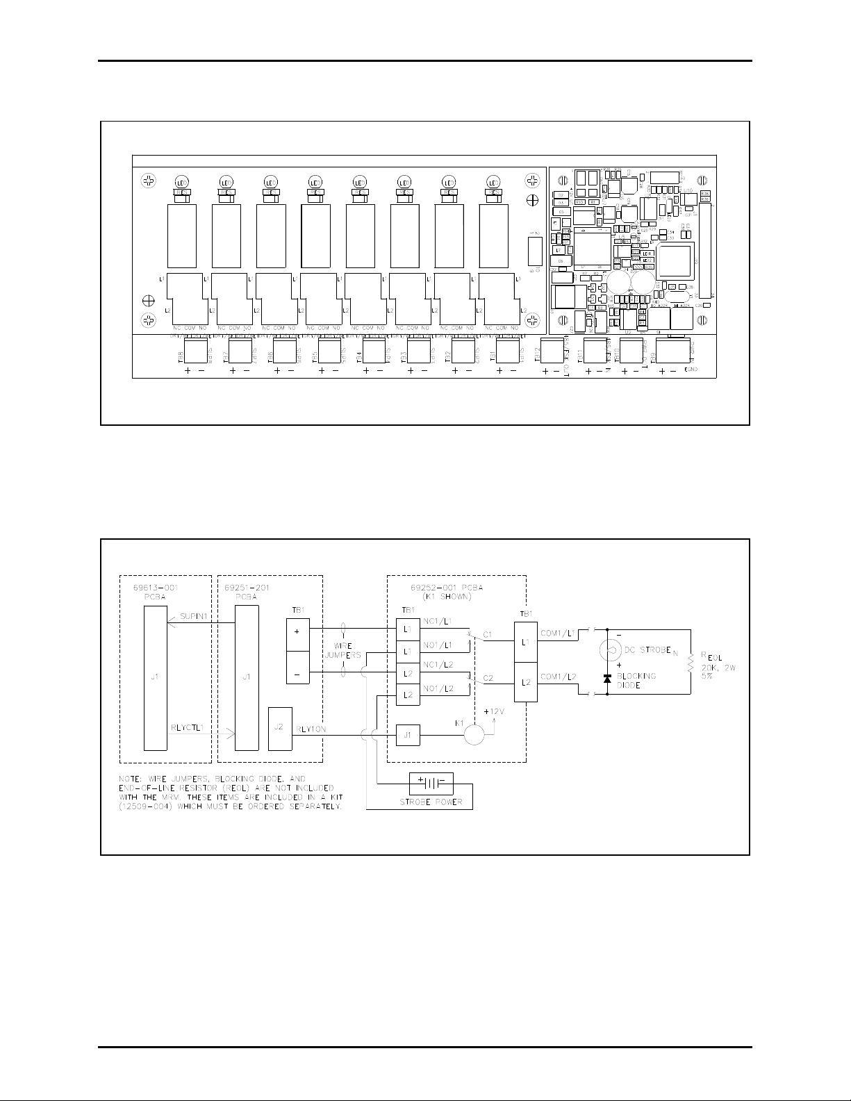
Figure 1. Monitored Relay Module
Figure 2. MRM Block Diagram
f:\standard ioms - current release\42004 instr. manuals\42004-716l2c.doc
05/12
Page 3

Pub. 42004-716L2C
Model 12579-003 Monitored Relay Module Page
3 of 16
Interfaces
The Model 12579-003 MRM interfaces to a Page/Party® Interface (PPI) card in the ADVANCE control
cabinet via the system page line (FSK link).
Installation Safety Guidelines
Please adhere to all warnings, safety, and operating instructions on the unit and in the installation manual.
WARNING
1. Disconnect power before servicing. Do not disconnect the equipment while circuit is energized.
2. Avoid servicing the unit during electrical storms.
3. Do not touch uninsulated wires.
f:\standard ioms - current release\42004 instr. manuals\42004-716l2c.doc
05/12
Page 4

Pub. 42004-716L2C
Model 12579-003 Monitored Relay Module Page
4 of 16
Installation Guidelines
1. Notify plant personnel of a system shutdown prior to servicing the unit.
2. Disconnect power before installing or removing the MRM.
Mounting
To install the module into the Snaptrack, slide either the right or left edge of the module into the top
groove on the track. On the opposite side, press firmly on the top and bottom corners of the module until
they snap into the groove. Carefully press from each corner toward the center and simultaneously snap
the edges firmly into place.
Power
After the MRM is installed onto the Snaptrack, 12 V dc power is brought in from the auxiliary power
supply and terminated on TB9 (PWR IN). The positive leg is connected to TB9-1(+) and the return leg is
landed on TB9-2(−). An earth ground is connected to TB9-3 (EGND). TB9 is paralleled with TB10.
TB10 (PWR OUT) may be used to distribute power to additional Snaptrack modules.
OTES:
N
Although power may be daisy-chained between MRMs and other Snaptrack modules, the preferred
method of delivering power to these modules is by providing a dedicated cable run between each
module and the auxiliary power supply.
The auxiliary power supply return leg must be connected to earth ground for proper operation. The
physical connection should be made at the auxiliary power supply terminals.
The ground reference for this assembly must be identical to that of the enclosure.
The MRM does not contain any current-limiting for power. It is recommended that an external fuse
be provided with the appropriate voltage and current ratings. The selected fuse should be of the
slo-blo variety.
Data Communication Line
Terminal blocks TB11 and TB12 are for the page line connection (FSK data communication) from the
PPI card to additional MIM and MRM modules.
FSK Signal Gain
The FSK Signal Gain, R8, adjusts the FSK transmit signal strength. It is set at the factory and should not
be adjusted by the installer.
Relay - Contact Outputs
The MRM contains eight individually configurable relay-contact outputs, allowing it to control field
devices such as beacons. Connections with these field devices are made at connectors TB1 through TB8
of the 69252-001 Power Relay Module.
f:\standard ioms - current release\42004 instr. manuals\42004-716l2c.doc
05/12
Page 5

Pub. 42004-716L2C
Model 12579-003 Monitored Relay Module Page
5 of 16
Each connector corresponds to a single output (TB1 is used for output #1, TB2 is used for output #2,
etc.). If fewer than eight supervised relay-contact outputs are required, the unused outputs may be used to
receive inputs (dry contact closures or non-supervised 24 V dc wet contact closures) from field devices.
In this case, connections with these field devices are made at connectors TB1 through TB8 of the 69251201 Monitored-In-8 PCBA. Each of these outputs may be configured to operate in one of six modes.
Two of these six modes are used to control signaling devices, while the remaining four modes are used to
receive inputs (contact closures) from field devices.
Each mode requires a unique connection scheme between the external field devices and the
appropriate connector on the MRM. The connection scheme for each mode is described below.
Since the connection scheme is independent of which output is used, only Output #1 will be
discussed.
To ensure proper termination, ferrules must be crimped on the ends of all conductors that are terminated
on the terminal blocks. The size of the ferrule is dependent upon the size of the conductor used and can
be sourced from any supplier such as Phoenix, Altec or Weidmuller. The terminals accept a maximum
conductor size of No. 12 AWG and a minimum conductor size of No. 28 AWG.
f:\standard ioms - current release\42004 instr. manuals\42004-716l2c.doc
05/12
Page 6
Pub. 42004-716L2C
Model 12579-003 Monitored Relay Module Page
Mode 0: Deactivate Circuit
6 of 16
In Mode 0, outputs may be used to control several signaling devices by connecting/disconnecting power
to these devices. In this mode, no supervision of the loop is supported. This mode supports both ac- and
dc-powered signaling devices.
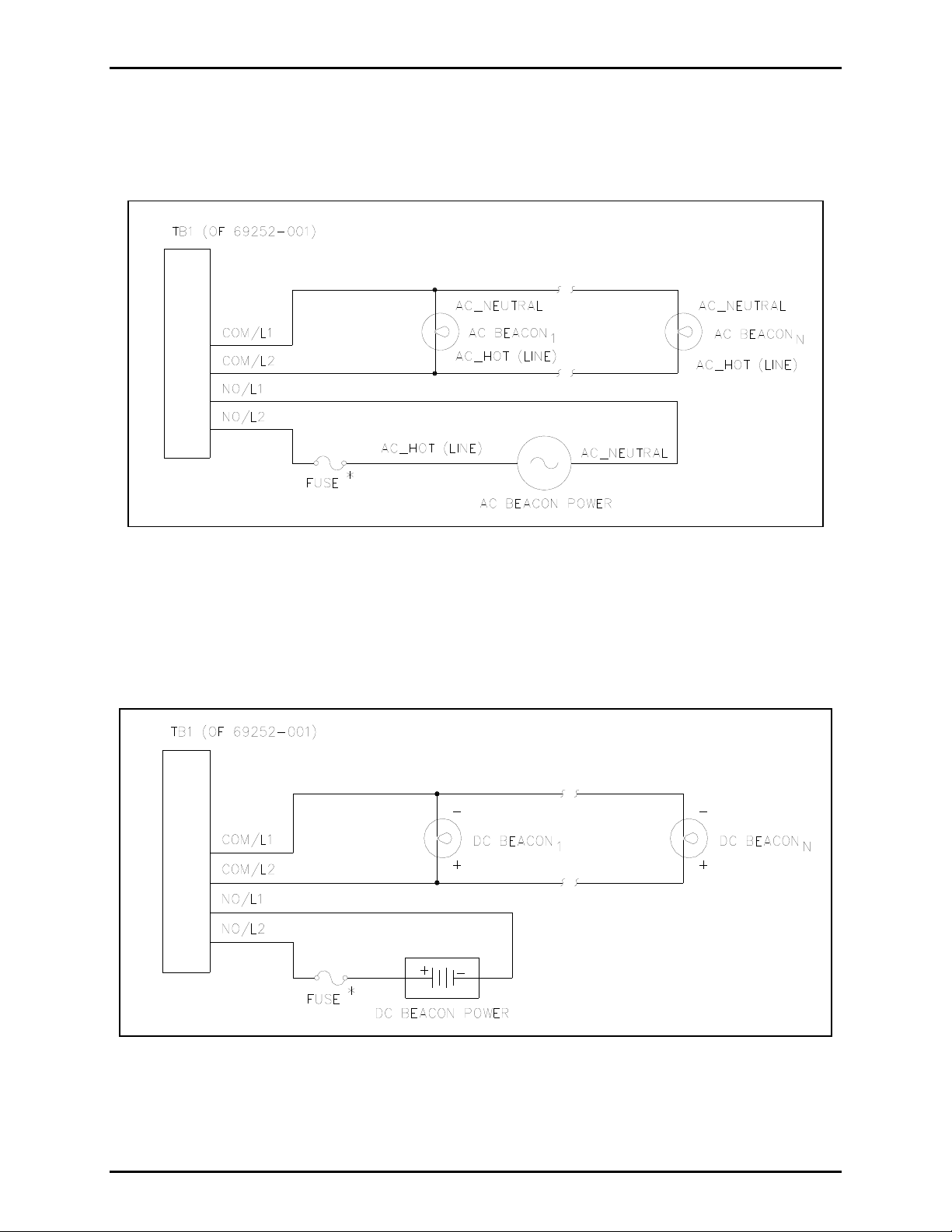
Figure 3. Deactivate Circuit - AC-Powered Beacons
Figure 3 shows the recommended wiring diagram for ac-powered signaling devices, while Figure 4 shows
the recommended wiring diagram for dc-powered signaling devices (using Output #1 as an example.)
OTE: The MRM does not contain any current-limiting for the signaling device power. It is
*N
recommended that an external fuse be provided for each output circuit with the appropriate voltage and
current ratings. The selected fuse should be of the slo-blo variety.
Figure 4. Deactivate Circuit - DC-Powered Beacons
f:\standard ioms - current release\42004 instr. manuals\42004-716l2c.doc
05/12
Page 7

Pub. 42004-716L2C
Model 12579-003 Monitored Relay Module Page
Mode 1: IDC Line Supervision Multiple Switch
7 of 16
In this mode any number of normally-open dry contact closures may be installed on the line. The loop is
monitored for ground faults and open circuits in Mode 1. The end-of-line device is a 20 k, 5% tolerance
resistor.
Figure 5. IDC Line Supervision Multiple Switch
OTE: The 20 k, 5% tolerance resistor is not included with the MRM. The resistor is included in a kit
N
(12509-004), which must be ordered separately.
f:\standard ioms - current release\42004 instr. manuals\42004-716l2c.doc
05/12
Page 8

Pub. 42004-716L2C
Model 12579-003 Monitored Relay Module Page
Mode 2: IDC Single Normally-Open (N.O.) Switch
8 of 16
In this configuration, only one normally-open dry contact closure may be installed per supervised line. In
this mode, the loop is monitored for open circuits, wire-to-wire short circuits (across + and −), and ground
faults. When the contact closure is not active (open), the loop appears as 20.1 k load (15 k in series
with 5.1 k). This appears on the input to the MIM and indicates a healthy loop. When the contact
closure is active (closed), the 15 k resistor is bypassed.
Figure 6. IDC Single Normally-Open Switch
When the contact closure is active (closed), the 15 k resistor is bypassed. In this case, output #1 only
sees a 5.1 k load. When this occurs, it indicates to the MRM that the contact closure is active. If there
is a short across L1 and L2, if either leg is grounded, or if a break occurs on either leg, the MRM indicates
that a fault has occurred.
OTE: The terminating resistors are not included with the MRM. These resistors are included in a kit
N
(12509-004), which must be ordered separately.
f:\standard ioms - current release\42004 instr. manuals\42004-716l2c.doc
05/12
Page 9

Pub. 42004-716L2C
Model 12579-003 Monitored Relay Module Page
Mode 3: IDC Single Normally-Closed (N.C.) Switch
9 of 16
In this configuration, only one normally-closed dry contact closure may be installed per supervised line.
In this mode, the loop is monitored for open circuits, wire-to-wire short circuits (across + and -), and
ground faults. When the contact closure is not active (closed), the 15 k is bypassed and the circuit sees
only the 5.1 k load.
Figure 7. IDC Single Normally-Closed Switch
This change is sensed by the MRM and indicates to the MRM that the contact closure is active. If there is
a short across L1 and L2, if either leg is grounded, or if a break occurs on either leg, the MRM indicates
that a fault has occurred.
OTE: The terminating resistors are not included with the MRM. These resistors are included in a kit
N
(12509-004), which must be ordered separately.
f:\standard ioms - current release\42004 instr. manuals\42004-716l2c.doc
05/12
Page 10

Pub. 42004-716L2C
Model 12579-003 Monitored Relay Module Page
Mode 4: IAC Line Supervision
10 of 16
In Mode 4, outputs can be used to control several dc-powered signaling devices by connecting/
disconnecting power to these devices. In addition, this loop is monitored for open circuits, wire-to-wire
short circuits (across + and −), and ground faults. If any of these three conditions are detected by the
MRM, the MRM indicates that a fault has occurred. Please note that monitoring of the loop only occurs
while the loop is inactive (signaling devices are off).
Figure 8. IAC Line Supervision – DC-Powered Beacons
It is recommended that Mode 4 only be used with dc-powered signaling devices. In Mode 4, one
blocking diode must be provided for every signaling device connected to the loop. Note that some
signaling devices already include a blocking diode in the unit - in this case, no additional blocking diode
is required. The end-of-line device is a 20 k, 2-watt, 5% tolerance resistor. Please observe all polarities
as indicated in Figure 8 above.
OTE: The blocking diodes, the wire jumpers, and the 20 k, 2-watt, 5% tolerance resistor are not
N
included with the MRM. These components are included in a kit (12509-004), which must be ordered
separately.
OTE: The MRM does not contain any current-limiting for the signaling device power. It is
*N
recommended that an external fuse be provided for each output circuit with the appropriate voltage and
current ratings. The selected fuse should be of the slo-blo variety.
f:\standard ioms - current release\42004 instr. manuals\42004-716l2c.doc
05/12
Page 11

Pub. 42004-716L2C
Model 12579-003 Monitored Relay Module Page
11 of 16
CAUTION
If ac-powered signaling devices are being used on an output loop configured for Mode 4 (Figure 9),
observe the following limitations necessary for reliable operation for the loop monitoring feature:
The dc-resistance measured across the loop (with both end-of-line device and the MRM
removed from the loop) must be at least 100 k
Do NOT use blocking diodes in this loop.
Figure 9. IAC Line Supervision – AC-Powered Beacons
f:\standard ioms - current release\42004 instr. manuals\42004-716l2c.doc
05/12
Page 12

Pub. 42004-716L2C
Model 12579-003 Monitored Relay Module Page
Mode 5: IDC Non-supervision Multiple Switch (Dry Contact)
12 of 16
In this mode, any number of normally-open dry contact closures can be installed on the line. The loop
will not
be monitored for any faults in Mode 5.
Figure 10. IDC Non-Supervision Multiple Switch (Dry Contact)
Mode 5: IDC Non-Supervision (Wet Contact)
In this wet contact mode, shorting jumpers for each input must be moved from the factory default of
“dry” to “wet” contact mode. When in “wet” contact mode, the input can be activated during a 0 V
condition or a 24 V condition. The factory default setting is “24 V dc input when active” (position 2-3).
If “0 V dc input when active” is desired, move jumper from position 2-3 to position 1-2. The loop will
be monitored for any faults in Mode 5. Ensure the polarity of input connection is correct as it is
not
polarity sensitive.
Figure 11. IDC Non-Supervision (Wet Contact)
f:\standard ioms - current release\42004 instr. manuals\42004-716l2c.doc
05/12
Page 13

Pub. 42004-716L2C
Model 12579-003 Monitored Relay Module Page
Table 1. Jumper Settings for Mode 5 Input Operation
13 of 16
Input No. Dry Contact
Input Selection
1 P1 – Pins 2 & 3
P2 – Pins 2 & 3
P3 – Pins 2 & 3
2 P4 – Pins 2 & 3
P5 – Pins 2 & 3
P6 – Pins 2 & 3
3 P7 – Pins 2 & 3
P8 – Pins 2 & 3
P9 – Pins 2 & 3
4 P10 – Pins 2 & 3
P11 – Pins 2 & 3
24 V DC Wet Contact Input
Selection
P1 – Pins 1 & 2
P2 – Pins 1 & 2
0 V dc – Active: P3 – Pins 1 & 2
24 V dc – Active: P3 – Pins 2 & 3
P4 – Pins 1 & 2
P5 – Pins 1 & 2
0 V dc – Active: P6 – Pins 1 & 2
24 V dc – Active: P6 – Pins 2 & 3
P7 – Pins 1 & 2
P8 – Pins 1 & 2
0 V dc – Active: P9 – Pins 1 & 2
24 V dc – Active: P9 – Pins 2 & 3
P10 – Pins 1 & 2
P11 – Pins 1 & 2
Factory Default
Setting
P1 – Pins 2 & 3
P2 – Pins 2 & 3
P3 – Pins 2 & 3
P4 – Pins 2 & 3
P5 – Pins 2 & 3
P6 – Pins 2 & 3
P7 – Pins 2 & 3
P8 – Pins 2 & 3
P9 – Pins 2 & 3
P10 – Pins 2 & 3
P11 – Pins 2 & 3
P12 – Pins 2 & 3
5 P13 – Pins 2 & 3
P14 – Pins 2 & 3
P15 – Pins 2 & 3
6 P16 – Pins 2 & 3
P17 – Pins 2 & 3
P18 – Pins 2 & 3
7 P19 – Pins 2 & 3
P20 – Pins 2 & 3
P21 – Pins 2 & 3
8 P22 – Pins 2 & 3
P23 – Pins 2 & 3
0 V dc – Active: P12 – Pins 1 & 2
24 V dc – Active: P12 – Pins 2 & 3
P13 – Pins 1 & 2
P14 – Pins 1 & 2
0 V dc – Active: P15 – Pins 1 & 2
24 V dc – Active: P15 – Pins 2 & 3
P16 – Pins 1 & 2
P17 – Pins 1 & 2
0 V dc – Active: P18 – Pins 1 & 2
24 V dc – Active: P18 – Pins 2 & 3
P19 – Pins 1 & 2
P20 – Pins 1 & 2
0 V dc – Active: P21 – Pins 1 & 2
24 V dc – Active: P21 – Pins 2 & 3
P22 – Pins 1 & 2
P23 – Pins 1 & 2
P12 – Pins 2 & 3
P13 – Pins 2 & 3
P14 – Pins 2 & 3
P15 – Pins 2 & 3
P16 – Pins 2 & 3
P17 – Pins 2 & 3
P18 – Pins 2 & 3
P19 – Pins 2 & 3
P20 – Pins 2 & 3
P21 – Pins 2 & 3
P22 – Pins 2 & 3
P23 – Pins 2 & 3
P24 – Pins 2 & 3
0 V dc – Active: P22 – Pins 1 & 2
P24 – Pins 2 & 3
24 V dc – Active: P22 – Pins 2 & 3
f:\standard ioms - current release\42004 instr. manuals\42004-716l2c.doc
05/12
Page 14

Pub. 42004-716L2C
Model 12579-003 Monitored Relay Module Page
Operation
All operation is controlled by the MCU and is set up in the configuration software. See the MCU
Configuration details in the system manual for all operation information.
How to Diagnose Assembly Faults
Symptom Action
14 of 16
MRM does not
communicate with
MCU.
MRM does not
recognize dry
inputs.
MRM does not
activate an alarm
with 24 V dc
applied to input
terminal. (Wet
contact mode
ONLY)
Verify power is applied to the MRM
Verify page line is connected to the MRM
Verify address of MRM agrees with the setup configuration
Ensure CPU PCBA is correctly connected via J1
Call for service of the MRM
Verify power is applied to the MRM
Verify page line is connected to the MRM
Verify end-of-line resistor(s) properly installed on each input circuit
Verify total loop resistance is less than 100
Call for service of the MRM
Verify that the jumper that selects the proper “__ V dc when active” mode is in
the correct position for the desired mode. Refer to Mode 5: IDC NonSupervision (Wet Contact) on page 12.
Verify that the input jumpers have been repositioned for “wet” operation.
Verify that input is within the acceptable dc voltage range (20–30 V dc).
Verify that the proper voltage polarity has been observed for external
connections to the input terminals.
Call for service of the MRM.
f:\standard ioms - current release\42004 instr. manuals\42004-716l2c.doc
05/12
Page 15

Pub. 42004-716L2C
Model 12579-003 Monitored Relay Module Page
15 of 16
Specifications
Electrical
Power requirements ................................................................................................................. 12 V dc 10%
Current draw ................................................. 1 amp maximum @ 12 V dc (does not include beacon power)
Number of output/input loops ..............................................................................................................8 loops
Maximum devices on output/input loop ................................. Limited by maximum current draw (Mode 0)
Unlimited (Mode 1)
One (Mode 2)
One (Mode 3)
Limited by maximum current draw (Mode 4)
Unlimited (Mode 5) (dry)
One (Mode 5) (wet)
Input/output ....................................................................................................................................... Power in
Power out
Page line (FSK) in
Page line (FSK) out
Eight field outputs/inputs
Data communications .............................................................................................................................. FSK
End-of -line device ............................................................................................................... 20 k (Mode 1)
5.1 k in series with 15 k across contact (Mode 2)
5.1 k in series with 15 k across contact (Mode 3)
20 k, 2-watt resistor (Mode 4 - up to 132 V ac/V dc)
None (Mode 5)
Field Outputs/Inputs
Mode 0
Maximum current draw (per output) ............................................................. 5 amps @ 24 V dc or 240 V ac
Maximum dc switching voltage ........................................................................................................ 150 V dc
Maximum ac switching voltage ........................................................................................................ 240 V ac
Mode 1
Contact closure resistance (activated) ................................................................................... 1 k maximum
Open fault detection ............................................................................................................ Minimum 65 k
Ground fault detection ......................................................................................... Less than 200 to ground
Modes 2 and 3
Contact closure resistance (Mode 2: activated/ Mode 3: de-activated) ................................ 3 k maximum
Open fault detection ............................................................................................................ Minimum 65 k
Ground fault detection ......................................................................................... Less than 200 to ground
Wire-to-wire short fault detection ........................................................................................ Less than 200
f:\standard ioms - current release\42004 instr. manuals\42004-716l2c.doc
05/12
Page 16

Pub. 42004-716L2C
Model 12579-003 Monitored Relay Module Page
16 of 16
Mode 4
Maximum current draw (per output) ............................................................. 5 amps @ 24 V dc or 132 V ac
Maximum dc switching voltage ....................................................................................................... 150 V dc
Maximum ac switching voltage ....................................................................................................... 132 V ac
Open fault detection ............................................................................................................ Minimum 65 k
Ground fault detection ......................................................................................... Less than 200 to ground
Wire-to-wire short fault detection .......................................................................................... Less than 1 k
Mode 5 (Dry)
Contact closure resistance ................................................................................................... 900 maximum
Mode 5 (Wet)
DC input voltage range ................................................................................. 20–30 V dc (24 V dc nominal)
Loop Supervision Limitations:
Cable limitations ........................................................................................ 100 maximum loop resistance
Resistance across loop (excluding end-of-line device) ...................................................... 100 k minimum
Terminals:
Minimum conductor size ......................................................................................... No. 28 AWG (0.5 mm
Maximum conductor size ......................................................................................... No. 12 AWG (3.0 mm
Mechanical
2
2
Unit dimensions ..................................................... 4.00 H 10.5 W 2.25 D inches (102 267 58 mm)
Unit weight ..................................................................................................................... 1.75 lbs. maximum
Environmental
Temperature range (operating/storage) ................................................. −30 C to 70 C (−22 F to 158 F)
Humidity .......................................................................................... 95% non-condensing relative humidity
Replacement Parts
Part Number Description
69613-001 CPU PCBA
69251-201 Monitored In 8 PCBA
69252-001 Power Relay Module
)
)
References
Published By Title GAI-Tronics Ref. No.
GAI-Tronics
f:\standard ioms - current release\42004 instr. manuals\42004-716l2c.doc
05/12
Monitored Relay Module Assembly Drawing 73568
Page 17

Warranty
Equipment. GAI-Tronics warrants for a period of one (1) year from the date of shipment, that any
GAI-Tronics equipment supplied hereunder shall be free of defects in material and workmanship, shall
comply with the then-current product specifications and product literature, and if applicable, shall be fit
for the purpose specified in the agreed upon quotation or proposal document. If (a) Seller’s goods prove
to be defective in workmanship and/or material under normal and proper usage, or unfit for the purpose
specified and agreed upon, and (b) Buyer’s claim is made within the warranty period set forth above,
Buyer may return such goods to GAI-Tronics nearest depot repair facility, freight prepaid, at which time
they will be repaired or replaced, at Seller’s option, without charge to Buyer. Repair or replacement shall
be Buyer’s sole and exclusive remedy. The warranty period on any repaired or replacement equipment
shall be the greater of the ninety (90) day repair warranty or one (1) year from the date the original
equipment was shipped. In no event shall GAI-Tronics warranty obligations with respect to equipment
exceed 100% of the total cost of the equipment supplied hereunder. Buyer may also be entitled to the
manufacturer’s warranty on any third-party goods supplied by GAI-Tronics hereunder. The applicability
of any such third-party warranty will be determined by GAI-Tronics.
Services. Any services GAI-Tronics provides hereunder, whether directly or through subcontractors,
shall be performed in accordance with the standard of care with which such services are normally
provided in the industry. If the services fail to meet the applicable industry standard, GAI-Tronics will reperform such services at no cost to buyer to correct said deficiency to Company's satisfaction provided
any and all issues are identified prior to the demobilization of the Contractor's personnel from the work
site. Re-performance of services shall be Buyer's sole and exclusive remedy, and in no event shall GAITronics warranty obligations with respect to services exceed 100% of the total cost of the services
provided hereunder.
Warranty Periods. Every claim by Buyer alleging a defect in the goods and/or services provided
hereunder shall be deemed waived unless such claim is made in writing within the applicable warranty
periods as set forth above. Provided, however, that if the defect complained of is latent and not
discoverable within the above warranty periods, every claim arising on account of such latent defect shall
be deemed waived unless it is made in writing within a reasonable time after such latent defect is or
should have been discovered by Buyer.
Limitations / Exclusions. The warranties herein shall not apply to, and GAI-Tronics shall not be
responsible for, any damage to the goods or failure of the services supplied hereunder, to the extent
caused by Buyer’s neglect, failure to follow operational and maintenance procedures provided with the
equipment, or the use of technicians not specifically authorized by GAI-Tronics to maintain or service the
equipment. THE WARRANTIES AND REMEDIES CONTAINED HEREIN ARE IN LIEU OF AND
EXCLUDE ALL OTHER WARRANTIES AND REMEDIES, WHETHER EXPRESS OR IMPLIED BY
OPERATION OF LAW OR OTHERWISE, INCLUDING ANY WARRANTIES OF
MERCHANTABILITY OR FITNESS FOR A PARTICULAR PURPOSE.
Return Policy
If the equipment requires service, contact your Regional Service Center for a return authorization number
(RA#). Equipment should be shipped prepaid to GAI-Tronics with a return authorization number and a
purchase order number. If the equipment is under warranty, repairs or a replacement will be made in
accordance with the warranty policy set forth above. Please include a written explanation of all defects to
assist our technicians in their troubleshooting efforts.
Call 800-492-1212 (inside the USA) or 610-777-1374 (outside the USA) for help identifying the
Regional Service Center closest to you.
(Rev. 10/06)
 Loading...