


Pub. 42004-609L2C
GAI-TRONICS® CORPORATION
A HUBBELL COMPANY
Model 12579-001
Monitored Relay Module
Confidentiality Notice
This manual is provided solely as an operational, installation, and maintenance guide and contains
sensitive business and technical information that is confidential and proprietary to GAI-Tronics. GAITronics retains all intellectual property and other rights in or to the information contained herein, and such
information may only be used in connection with the operation of your GAI-Tronics product or system.
This manual may not be disclosed in any form, in whole or in part, directly or indirectly, to any third party.
How to Use the Assembly/Model
Application
The Model 12579-001 Monitored Relay Module (MRM) is a Snaptrack™ module designed for use in the
SmartSeries systems. GAI-Tronics uses the MRM to provide a maximum of eight independently
controlled relay-contact outputs. Each of the eight relay-contact outputs has an associated LED to
indicate its current status. These relay-contact outputs are typically used to switch power to signaling
devices, such as beacons, on command from the 69254 Series or 69440 Series Master Control Unit
(MCU).
The MRM also provides the capability of supervising the cable runs to these signaling devices for such
abnormal conditions as open-circuit conditions, ground faults, and wire-to-wire short circuit conditions.
In addition, if fewer than eight relay-contact outputs are needed for a particular application, then the
MRM may also be used to receive inputs (dry contact closures) from field devices. The MRM is
comprised of three main components: the 69248-101 Central Processing Unit (CPU) Printed Circuit
Board Assembly (PCBA), the 69252-001 Power Relay Module, and the 69251-101 Monitored In 8
PCBA.
The MRM is designed to be mounted in a Snaptrack™ that is then installed in an equipment rack.
Snaptrack™ is a grooved plastic channel designed to allow PCBAs to securely ‘snap’ into the groove.
The Snaptrack™ provides flexible installation because the track may be installed inside a rack wherever
it is convenient.
The MRM communicates with the MCU via an RS-485 link. This RS-485 link is periodically monitored
by the MCU for any interruptions in communication. The MCU uses this communication channel to
control activation/de-activation of the MRM’s relay-contact outputs. In turn, the MRM uses this
communication channel to report to the MCU any cable run fault conditions that are detected. The MCU
identifies a particular MRM on this RS-485 link by its module address. This module address is set by
rotary hex switch S1 of the MRM (located on the CPU PCBA.) The range of valid settings is from 0x5
(hex) to 0xE (hex).
GAI-Tronics Corporation 400 E. Wyomissing Ave. Mohnton, PA 19540 USA
610-777-1374 800-492-1212 Fax: 610-796-5954
ISIT WWW.GAI-TRONICS.COM FOR PRODUCT LITERATURE AND MANUALS
V

Pub. 42004-609L2C
Model 12579-001 Monitored Relay Module Page:
Hardware Configuration
2 of 14
Block Diagram
Figure 1. Monitored Relay Module
Figure 2. MRM Block Diagram
Interfaces
The Model 12579-001 MRM interfaces to the MCU via RS-485.
f:\standard ioms - current release\42004 instr. manuals\42004-609l2c.doc
10/11
Pub. 42004-609L2C
Model 12579-001 Monitored Relay Module Page:
Installation
Installation Safety Guidelines
Please adhere to all warnings, safety, and operating instructions on the unit and in the installation
manual.
3 of 14
WARNING
1. Disconnect power before servicing. Do not disconnect the equipment while circuit is energized.
2. Avoid servicing the unit during electrical storms.
3. Do not touch uninsulated wires.
Installation Guidelines
1. Notify plant personnel of a system shutdown prior to servicing the unit.
2. Disconnect power before installing or removing the MRM.
Mounting
To install the module into the Snaptrack™, slide either the right or left edge of the module into the top
groove on the track. On the opposite side, press firmly on the top and bottom corners of the module
until they snap into the groove. Carefully press from each corner toward the center and simultaneously
snap the edges firmly into place.
Power
After the MRM is installed onto the Snaptrack™, 12 V dc power is brought in from the auxiliary power
supply and terminated on TB9 (PWR IN). The positive leg is connected to TB9-1(+) and the return leg is
landed on TB9-2(−). An earth ground is connected to TB9-3 (EGND). TB9 is paralleled with TB10.
TB10 (PWR OUT) may be used to distribute power to additional Snaptrack™ modules.
N
OTES:
• Although power may be daisy-chained between MRMs and other Snaptrack™ modules, the preferred
method of delivering power to these modules is by providing a dedicated cable run between each
module and the power supply.
• The auxiliary power supply is not part of the 10457 Series Card Rack Assembly. The card rack
power supply is not used to provide power to the Snaptrack™ modules. An additional power supply
must be included in the cabinet to support these modules.
• The auxiliary power supply return leg must be connected to earth ground for proper operation. The
physical connection should be made at the auxiliary power supply terminals.
• The ground reference for this assembly must be identical to that of the card rack.
• The MRM does not contain any current-limiting for power. It is recommended that an external fuse
be provided with the appropriate voltage and current ratings. The selected fuse should be of the
Slo-Blo
®
variety.
f:\standard ioms - current release\42004 instr. manuals\42004-609l2c.doc
10/11
Pub. 42004-609L2C
Model 12579-001 Monitored Relay Module Page:
Data Communication Line
4 of 14
Terminal block TB21 has been provided to distribute the RS-485 data communication line to additional
Snaptrack™ modules. If there are no additional Snaptrack™ modules, connect a 47207-151 150-ohm,
½ watt terminating resistor (sold separately) across TB12 of the 69251-101, or install a jumper across the
pins of P2 on the 69248-101 CPU PCBA.
CAUTION
The RS-485 line is polarity-sensitive. Be sure to maintain circuit polarity throughout installation.
N
OTES:
1. The conductor terminated on TB12
should be a twisted pair.
2. Only one termination is to be applied to an RS-485 circuit - either a 150-ohm resistor across TB12, or
a jumper across the pins of P2.
Relay - Contact Outputs
The MRM contains eight individually configurable relay-contact outputs, allowing it to control field
devices such as beacons. Connections with these field devices are made at connectors TB1 through TB8
of the 69252-001 Power Relay Module.
Each connector corresponds to a single output (TB1 is used for output #1, TB2 is used for output #2,
etc.). If fewer than eight supervised relay-contact outputs are required, the unused outputs may be used
to receive inputs (dry contact closures) from field devices.
In this case, connections with these field devices are made at connectors TB1 through TB8 of the
69251-101 Monitored-In-8 PCBA. Each of these outputs may be configured to operate in one of six
modes. Two of these six modes are used to control signaling devices, while the remaining four modes
are used to receive inputs (contact closures) from field devices.
Each mode requires a unique connection scheme between the external field devices and the
appropriate connector on the MRM. The connection scheme for each mode is described
below. Since the connection scheme is independent of which output is used, only Output #1
will be discussed.
To ensure proper termination, ferrules must be crimped on the ends of all conductors that are terminated
on the terminal blocks. The size of the ferrule is dependent upon the size of the conductor used and can
be sourced from any supplier such as Phoenix, Altec or Weidmuller. The terminals accept a maximum
conductor size of No. 12 AWG and a minimum conductor size of No. 28 AWG.
f:\standard ioms - current release\42004 instr. manuals\42004-609l2c.doc
10/11
Pub. 42004-609L2C
Model 12579-001 Monitored Relay Module Page:
5 of 14
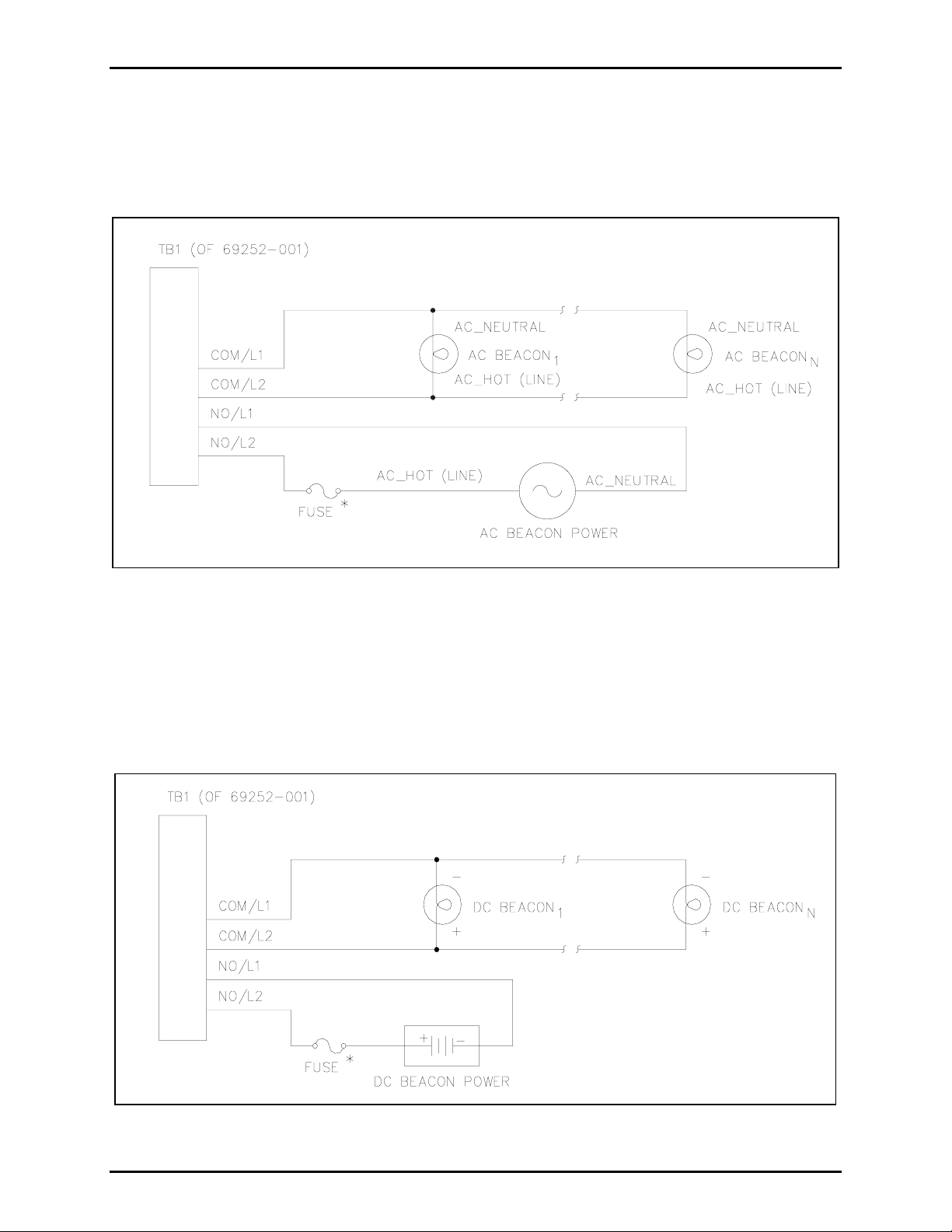
Mode 0: Deactivate Circuit
In Mode 0, output #1 may be used to control several signaling devices by connecting/disconnecting
power to these devices. In this mode, no supervision of the loop is supported. This mode supports both
ac- and dc-powered signaling devices.
Figure 3. Deactivate Circuit - AC-Powered Beacons
Figure 3 shows the recommended wiring diagram for ac-powered signaling devices, while Figure 4
shows the recommended wiring diagram for dc-powered signaling devices (using Output #1 as an
example.)
*N
OTE: The MRM does not contain any current-limiting for the signaling device power. It is
recommended that an external fuse be provided for each output circuit with the appropriate voltage and
current ratings. The selected fuse should be of the Slo-Blo
®
variety.
Figure 4. Deactivate Circuit - DC-Powered Beacons
f:\standard ioms - current release\42004 instr. manuals\42004-609l2c.doc
10/11
 Loading...