

Page 1

Pub. 42003-262A
GAI-TRONICS® CORPORATION
A HUBBELL COMPANY
Access Panel-to-Fiber Interface Kits
Models 12577-011 through 12577-018
Confidential ity Notice
This manual is provided solely as an operational, installation, and maintenance guide and contains
sensitive business and technical information that is confidential and proprietary to GAI-Tronics.
GAI-Tronics retains all intellectual property and other rights in or to the information contained herein,
and such information may only be used in connection with the operation of your GAI-Tronics product or
system. This manual may not be disclosed in any form, in whole or in part, directly or indirectly, to any
third party.
General Information
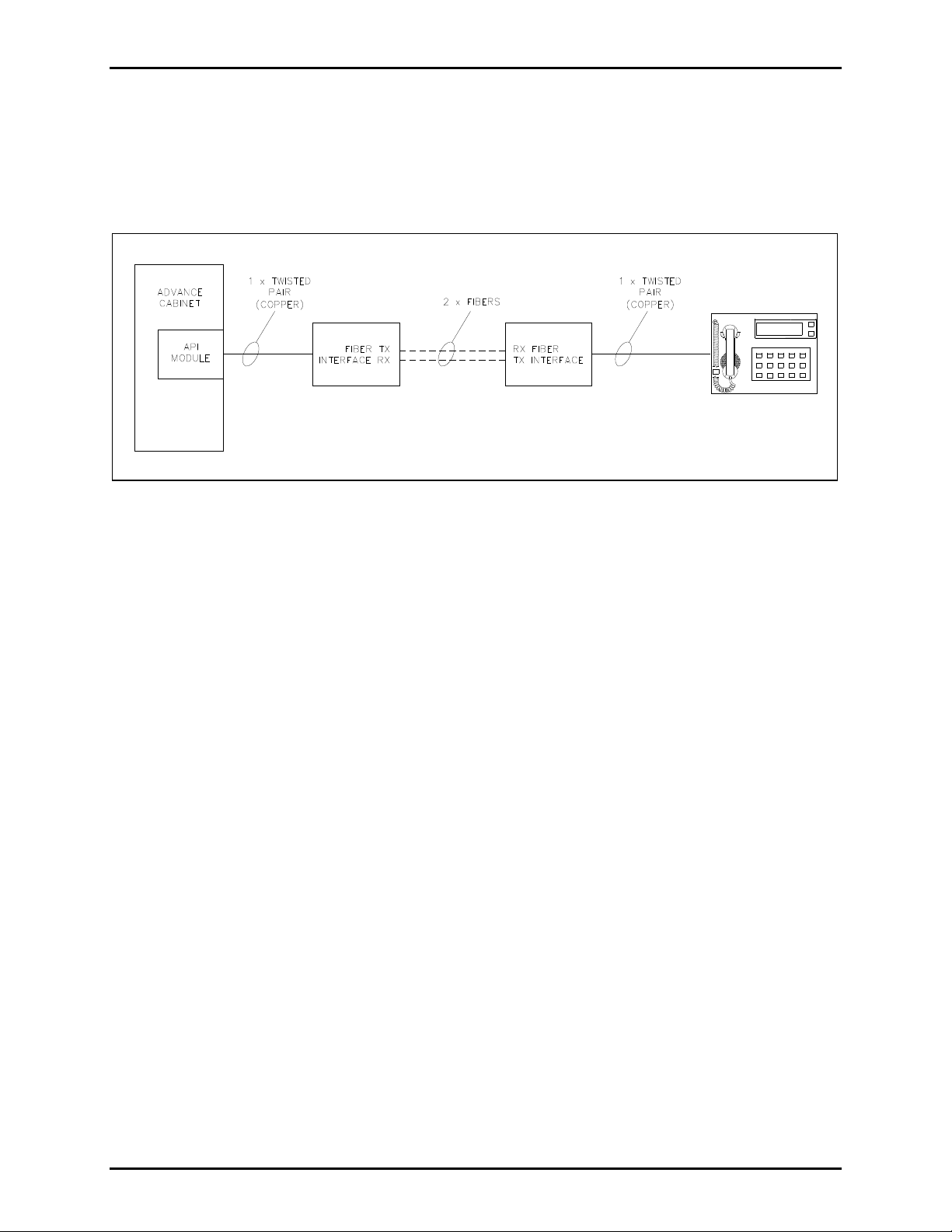
The Model 12577-011 through 12577-018 Access Panel-to-Fiber Interface Kits are used in pairs to allow
access panels to be connected to ADVANCE cabinets using either single-mode or multi-mode fiber. The
Access Panel-to-Fiber Interface is available for either indoor or outdoor mounting. The following kits are
described in this manual:
Model Description
12577-011 Indoor Access Panel to Multi-Mode Fiber Kit, ST Connector
12577-012 Indoor Access Panel to Multi-Mode Fiber Kit, SC Connector
12577-013 Indoor Access Panel to Single Mode Fiber Kit, ST Connector
12577-014 Indoor Access Panel to Single Mode Fiber Kit, SC Connector
12577-015 Outdoor Access Panel to Multi-Mode Fiber Kit, ST Connector
12577-016 Outdoor Access Panel to Multi-Mode Fiber Kit, SC Connector
12577-017 Outdoor Access Panel to Single Mode Fiber Kit, ST Connector
12577-018 Outdoor Access Panel to Single Mode Fiber Kit, SC Connector
Each of the indoor kits includes the following components:
Qty Description
1 Access Panel Fiber PCBA
1 Indoor single card housing
1 120/240 V ac plug-in power supply
Each of the outdoor kits includes the following components:
Qty Description
1 Access Panel Fiber PCBA
1 Outdoor dual card housing with 24 V dc power adapter
GAI-Tronics Corporation 400 E. Wyomissing Ave. Mohnton, PA 19540 USA
610-777-1374 800-492-1212 Fax: 610-796-5954
V
ISIT WWW.GAI-TRONICS.COM FOR PRODUCT LITERATURE AND MANUALS
Page 2
Pub. 42003-262A
ODEL 12577-011 & 12577-018 ACCESS PANEL-TO-FIBER INTERFACE KITS Page 2 of 4
M
The indoor single card housing is constructed of powder coated 16-gauge steel and can be mounted on
standard DIN rail or wall mounted.
The outdoor dual card housing is a plastic enclosure that can be mounted to a wall or pole. It has an
internal power adapter inside that accepts ac or dc voltage input with a 24 V dc output to the Fiber Optic
Link card. The outdoor card housing should be mounted to a wall or pole with the three screws provided.
Figure 1. Typical Block Diagram
Installation
1. Mount the indoor card housing to the provided DIN rail. Mount the outdoor dual card housing with
the three screws provided. See Figure 3 for mounting details.
2. Compress the plastic card guide latch on the right side of the PCBA to slide it out partially from the
housing. Carefully slide the card out of the housing to make the following connections to the PCBA.
Refer to Figure 2 for data card connectors and LEDs. The PCBA should not need to be removed
from the housing to make the connections.
3. Connect fiber optic cable to card. Connect fiber to the transmit and receive terminals marked TX and
RX. Fiber cable should always be routed loosely avoiding tight bends.
4. Connect the copper pair from the ADVANCE cabinet API module or the access panel by connecting
to the black TIP and RING screw-down term inals.
5. Connect a 24–56 V dc (70mA minimum) power source to the 48 V dc terminal on the PCBA.
6. Slide the card back into the housing and lock into place.
7. Close the outdoor housing and secure with lock.
e:\standard ioms - current release\42003 kit manuals\420 03-262a.doc
11/13
Page 3

Pub. 42003-262A
ODEL 12577-011 & 12577-018 ACCESS PANEL-TO-FIBER INTERFACE KITS Page 3 of 4
M
Setup
1. Ensure both fiber interfaces are installed and powered up. Ensure that the TX connector on the near
interface is connected to the RX connector on the far interface and vise-versa.
2. Transmit levels are set by the GAIN
used to indicate the optimum setting.
3. Move the GAIN
SELECT jumper to the highest position that will keep the green XMIT LED on, but
will not turn on the orange LIMIT LED.
4. Repeat for both fiber interfaces.
Figure 2. Data Card Connectors and LEDs
SELECT jumper on the PCBA. The XMIT and LIMIT LEDs are
Figure 3. Outdoor Housing Mounting Details
e:\standard ioms - current release\42003 kit manuals\420 03-262a.doc
11/13
Page 4

Pub. 42003-262A
ODEL 12577-011 & 12577-018 ACCESS PANEL-TO-FIBER INTERFACE KITS Page 4 of 4
M
Table 1. Data Card LEDs
LED Color On* Off
Fiber (FIBR) Yellow Fiber is connected between cards No fiber continuity
Alarm (ALRM) Red Loss of signal Normal operation
Receive (RCV) Green Signal received from fiber Low level or no signal received
from fiber
Transmit (XMIT) Green Signal received from copper Low level or no signal received
from copper
Limit Orange Copper input signal overload Normal operation
Power (PWR) Blue DC power connected No dc power connected
e:\standard ioms - current release\42003 kit manuals\420 03-262a.doc
11/13
Page 5

Warranty
Equipment. GAI-Tronics warrants for a period of one (1) year from the date of shipment, that any
GAI-Tronics equipment supplied hereunder shall be free of defects in material and workmanship, shall
comply with the then-current product specifications and product literature, and if applicable, shall be fit
for the purpose specified in the agreed-upon quotation or proposal document. If (a) Seller’s goods prove
to be defective in workmanship and/or material under normal and proper usage, or unfit for the purpose
specified and agreed upon, and (b) Buyer’s claim is made within the warranty period set forth above,
Buyer may return such goods to GAI-Tronics’ nearest depot repair facility, freight prepaid, at which time
they will be repaired or replaced, at Seller’s option, without charge to Buyer. Repair or replacement shall
be Buyer’s sole and exclusive remedy. The warranty period on any repaired or replacement equipment
shall be the greater of the ninety (90) day repair warranty or one (1) year from the date the original
equipment was shipped. In no event shall GAI-Tronics warranty obligations with respect to equipment
exceed 100% of the total cost of the equipment supplied hereunder. Buyer may also be entitled to the
manufacturer’s warranty on any third-party goods supplied by GAI-Tronics hereunder. The applicability
of any such third-party warranty will be determined by GAI-Tronics.
Services. Any services GAI-Tronics provides hereunder, whether directly or through subcontractors,
shall be performed in accordance with the standard of care with which such services are normally
provided in the industry. If the services fail to meet the applicable industry standard, GAI-Tronics will
re-perform such services at no cost to buyer to correct said deficiency to Company's satisfaction provided
any and all issues are identified prior to the demobilization of the Contractor’s personnel from the work
site. Re-performance of services shall be Buyer’s sole and exclusive remedy, and in no event shall GAITronics warranty obligations with respect to services exceed 100% of the total cost of the services
provided hereunder.
Warranty Periods. Every claim by Buyer alleging a defect in the goods and/or services provided
hereunder shall be deemed waived unless such claim is made in writing within the applicable warranty
periods as set forth above. Provided, however, that if the defect complained of is latent and not
discoverable within the above warranty periods, every claim arising on account of such latent defect shall
be deemed waived unless it is made in writing within a reasonable time after such latent defect is or
should have been discovered by Buyer.
Limitations / Exclusions. The warranties herein shall not apply to, and GAI-Tronics shall not be
responsible for, any damage to the goods or failure of the services supplied hereunder, to the extent
caused by Buyer’s neglect, failure to follow operational and maintenance procedures provided with the
equipment, or the use of technicians not specifically authorized by GAI-Tronics to maintain or service the
equipment. THE WARRANTIES AND REMEDIES CONTAINED HEREIN ARE IN LIEU OF AND
EXCLUDE ALL OTHER WARRANTIES AND REMEDIES, WHETHER EXPRESS OR IMPLIED BY
OPERATION OF LAW OR OTHERWISE, INCLUDING ANY WARRANTIES OF
MERCHANTABILITY OR FITNESS FOR A PARTICULAR PURPOSE.
Return Policy
If the equipment requires service, contact your Regional Service Center for a return authorization number
(RA#). Equipment should be shipped prepaid to GAI-Tronics with a return authorization number and a
purchase order number. If the equipment is under warranty, repairs or a replacement will be made in
accordance with the warranty policy set forth above. Please include a written explanation of all defects to
assist our technicians in their troubleshooting efforts.
Call 800-492-1212 (inside the USA) or 610-777-1374 (outside the USA) for help identifying the
Regional Service Center closest to you.
(Rev. 10/06)
 Loading...