

Page 1
Pub. 42004-436C
GAI-TRONICS® CORPORATION
A HUBBELL COMPANY
Model 12576-504 Rack-Mount
System Status Panel with LCD Display
Confidential ity Notice
This manual is provided solely as an operational, installation, and maintenance guide and contains
sensitive business and technical information that is confidential and proprietary to GAI-Tronics.
GAI-Tronics retains all intellectual property and other rights in or to the information contained herein,
and such information may only be used in connection with the operation of your GAI-Tronics product or
system. This manual may not be disclosed in any form, in whole or in part, directly or indirectly, to any
third party.
General Information
Product Overview
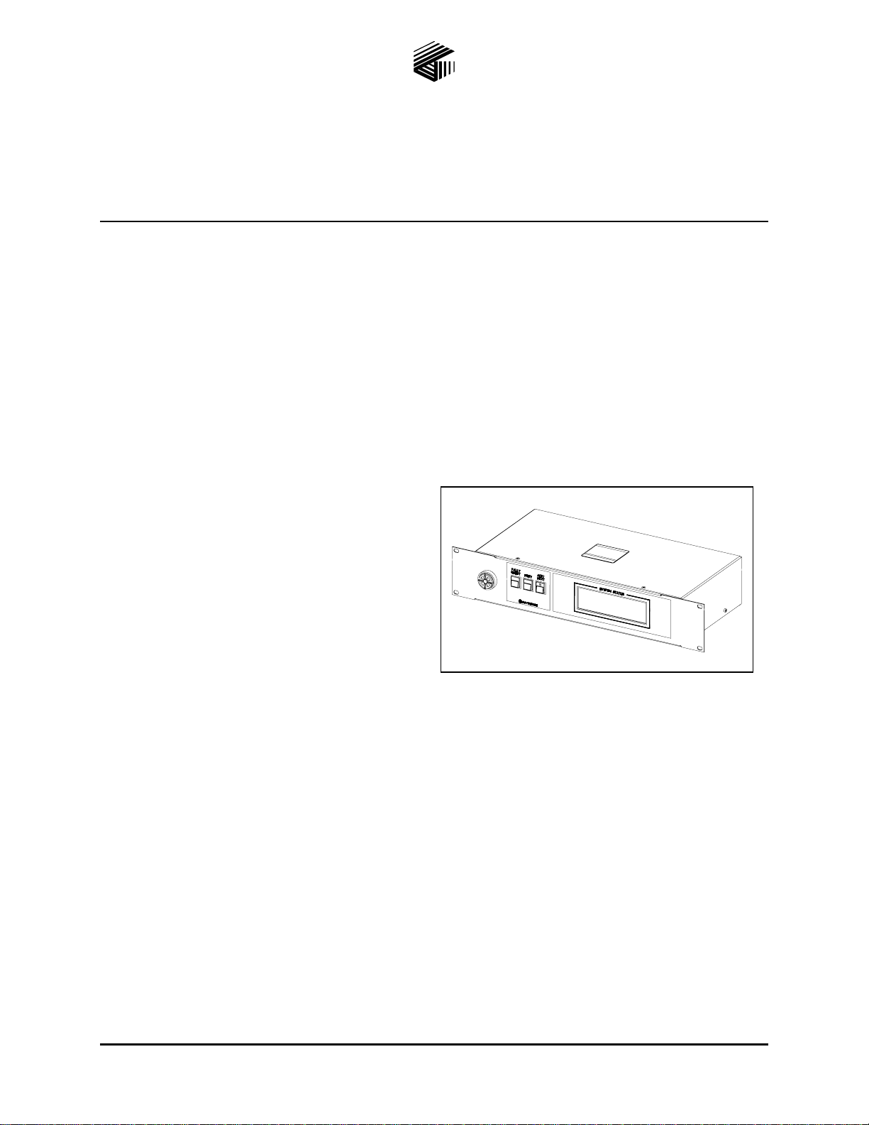
The Model 12576-504 System Status Panel is a
component of GAI-Tronics’ ADVANCE System.
The operation of each system status panel is
programmed at the ADVANCE System control
cabinet. Operating capabilities include: reset of
fault alarms, and a text display of the system
operating status.
The system status panel includes a sounder
(sonalert) to annunciate system alarm /trouble
conditions.
Figure 1. Model 12576-504
Fea tures
• 12 V dc input power • LCD text display
• Standard 2U, 19-inch EIA rack-mount design • Sonalert with volume control
• Three push-button switches • One LED switch indicator
N
OTE: If this unit is to be used as a replacement for a previous system status panel it will be necessary to
make changes to the ADVANCE configuration file before use. Please contact GAI-Tronics Service for
details.
GAI-Tronics Corporation 400 E. Wyomissing Ave. Mohnton, PA 19540 USA
610-777-1374 800-492-1212 Fax: 610-796-5954
V
ISIT WWW.GAI-TRONICS.COM FOR PRODUCT LITERATURE AND MANUALS
Page 2
Pub. 42004-436C
Model 12576-504 ADVANCE Rack-Mount System Status Panel with LCD Display Page: 2 of 9
Options/Accessories
Model Description
3308-50008-00 Power Supply Unit 120 V ac – 12 V dc @ 1 A
Installation
Important Safety Instructions
1. Read, follow, and retain instructions – All safety and operating instructions should be read and
followed before operating the unit. Retain instructions for future reference.
2. Heed warnings – Adhere to all warnings on the unit and in the operating instructions.
3. Attachments – Attachments not recommended by the product manufacturer should not be used, as
they may cause hazards.
4. Servicing – Do not attempt to service this unit by yourself. Opening or removing covers may expose
you to dangerous voltage or other hazards. Refer all servicing to qualified service personnel.
5. This permanently connected apparatus must operate from a UL Listed 12 V dc @ 1 A minimum
regulated power supply.
USA and Canada Consult the National Electrical Code (NFPA 70), Canadian Standards Association
(CSA 22.1), and local codes for specific requirements regarding your installation. Class 2 circuit wiring
must be performed in accordance with NEC 725.55.
Mounting
NOTES:
1. Mounting hardware is not included with this assembly and must be purchased separately.
2. Due to the insertion depth and weight of this system status panel, chassis supports should be installed
under the unit on both sides to prevent twisting of the front panel.
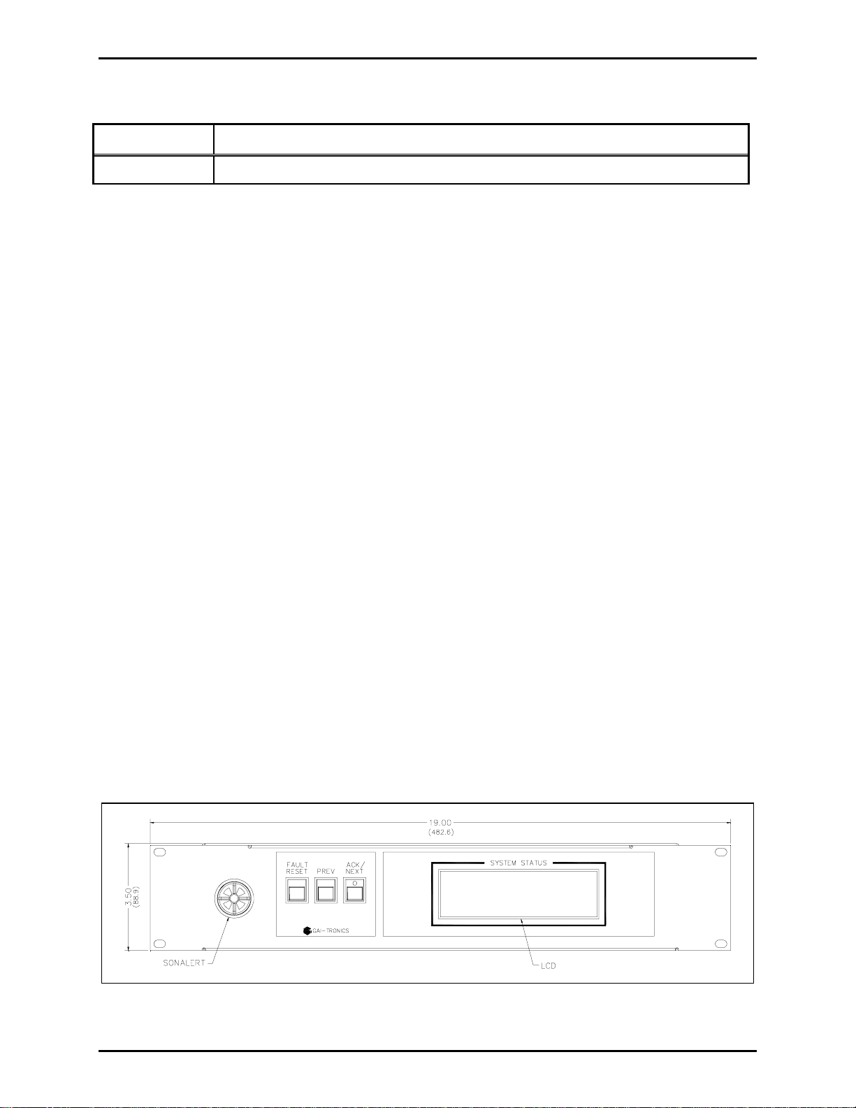
Remove the system status panel from its protective packing. Position the system status panel in the 19inch EIA cabinet (or rack) and secure with the appropriate screws. A plastic shoulder washer should be
installed behind each screw to prevent scratching of the painted finish.
Figure 2. System Status Panel - Front View
f:\standard ioms - current release\42004 instr. manuals\42004-436c.doc
01/12
Page 3
Pub. 42004-436C
Model 12576-504 ADVANCE Rack-Mount System Status Panel with LCD Display Page: 3 of 9
Field Wiring
TX/RX Data
The modular terminal block labeled +/−
TX/RX at the rear of the system status panel provides connection
for the data line to the API connection module (or DIN terminal blocks) at the ADVANCE system control
cabinet.
A twisted pair cable (minimum Category 3) should be used for this connection. Observe cable conductor
polarity (+/−) when making connections at the control cabinet: (+ connects to + and − connects to −). No
damage will occur if the polarity is reversed, but the system status panel will not function.
If installing this panel external to the ADVANCE System control cabinet, the maximum cable distance to
the cabinet is 3 km when using No. 24 AWG (Category 3) cable. Refer to Figure 3 for terminal block
location and Table 1 for additional details.
Table 1. Data Terminal Assignment
Label
+
− TB1-2
Internal Terminal
Number
TB1-1
Function or ACT Descripti on
Positive terminal of data line connection
(to designated + terminal at API connection module)
Negative terminal of data line connection
(to designated − terminal at API connection module)
f:\standard ioms - current release\42004 instr. manuals\42004-436c.doc
01/12
Page 4

Pub. 42004-436C
Model 12576-504 ADVANCE Rack-Mount System Status Panel with LCD Display Page: 4 of 9
Power
The modular terminal block labeled CLASS
2 12V DC provides power connection for the system status
panel. Refer to Table 2 and Figure 3 for terminal details.
Table 2. DC Power Terminal Assignment
Label
+
−
GND
Internal Terminal
Number
TB2-1
TB2-2
TB2-3 Frame/chassis ground
Function or ACT Descripti on
Positive terminal of external power supply
(Red wire from 12 V dc power supply)
Negative terminal of external power supply
(Black wire from 12 V dc power supply)
N
OTE: The system status panel does not have an on/off power switch and will power up immediately
upon application of 12 V dc power. The ADVANCE System control cabinet must also be powered and
running before the system status panel is operational. The A
CK/NEXT switch LED on the system status
panel will flash, the sonalert will sound and the display will read “No communication with ADVANCE”
until data communication is established with the ADVANCE control cabinet.
Grounding
The system status panel is equipped with a ground stud on the rear panel. The ground stud is supplied
with two KEPS type hex nuts. Internally, the ground stud connects to chassis and the ground terminal at
TB3-3. Be sure to connect this ground stud to the appropriate ground bar or ground terminals within the
cabinet using a #6 ring lug crimped to a No. 14 AWG green/yellow (or green) wire.
Figure 3. System Status Panel Rear View
f:\standard ioms - current release\42004 instr. manuals\42004-436c.doc
01/12
Page 5

Pub. 42004-436C
Model 12576-504 ADVANCE Rack-Mount System Status Panel with LCD Display Page: 5 of 9
Settings and Adjustments
User Adjustments
Sonalert Volume Adjus tment
The volume adjustment on the rear panel adjusts the volume level of the sonalert alarm. Clockwise
rotation will increase the volume and counterclockwise rotation will decrease the volume.
Internal Adjustments
Removing the Cover
Remove the two screws from top cover, and the two screws from each side (a total of six). Open the
system status panel by lifting and rotating the cover back 180º and place on a flat surface. Be careful not
to disconnect any cables.
Figure 4. Interior View of System Status Panel
f:\standard ioms - current release\42004 instr. manuals\42004-436c.doc
01/12
Page 6

Pub. 42004-436C
Model 12576-504 ADVANCE Rack-Mount System Status Panel with LCD Display Page: 6 of 9
Jumper Settings
TX/RX Data
Jumper P9 provides a ground reference to the access panel data line. A similar jumper is located on the
Access Panel Interface (API) card in the system control cabinet. The data line must be ground referenced
on one side of the communication link but not both. Place P9 in the GND position to create a ground
reference. Place P9 in the FLOAT position (default) to remove the ground reference. Refer to Figure 5
for jumper location.
Potentiometer Adjustments
LCD Display Brightness
R2 adjust the brightness of the backlight of the display. Clockwise rotation increases the brightness.
Refer to Figure 5 for potentiometer location.
LCD Display Contrast
R1 adjusts the contrast of the display. Clockwise rotation increases the contrast. Refer to Figure 5 for
potentiometer location.
Figure 5. System Status Panel Board
Attaching the Cover
After all adjustments have been completed, replace the cover over lower chassis, being careful not to
pinch any cables. Secure the cover using the six screws originally removed from the top and sides.
f:\standard ioms - current release\42004 instr. manuals\42004-436c.doc
01/12
Page 7

Pub. 42004-436C
Model 12576-504 ADVANCE Rack-Mount System Status Panel with LCD Display Page: 7 of 9
Operation
The system status panel operator is only capable of viewing the system operating status on the LCD
display. The following paragraphs provide a general overview of the system status panel features. Pushbutton switches provided on the system status panel are assigned specific system control functions.
Push-Button Swi tch Summary
Each push-button switch function is assigned a specific function. The following describes the function(s)
of each switch on the front panel of the system status panel:
A
CK/NEXT – the ack/next push button performs three unique functions, each of which is dependent upon
system status or conditions. The 1
event(s) or condition(s) in the system. The 2
depressed is used to acknowledge an event, causing the switch lamp to extinguish (if there are no other
unacknowledged events). The 1
events or conditions exist. The 3
acknowledged. The next function is used in conjunction with the previous push-button to navigate
forwards and backwards, respectively, through the history buffer of messages.
st
function is an illuminated state which indicates unacknowledged
st
and 2nd functions are sequenced repeatedly as long as outstanding
rd
function (next) is available only when all events or conditions are
nd
function is an acknowledge function, which when
REV – is an abbreviation for previous and is used in conjunction with the next function (of the ack/next
P
push-button switch) to navigate forwards and backwards, respectively, through the history buffer of
messages.
F
AULT/RESET – the Fault/Reset push-button switch used to reset active alarms displayed on the LCD and
fault relay outputs at the ADVANCE System control cabinet, which are retained until the faulted
condition is corrected.
f:\standard ioms - current release\42004 instr. manuals\42004-436c.doc
01/12
Page 8

Pub. 42004-436C
Model 12576-504 ADVANCE Rack-Mount System Status Panel with LCD Display Page: 8 of 9
Maintenance
Troubles hooting
Symptom Possible Cause
The system status panel has lost data communication with the Access
Panel Interface (API) card at the ADVANCE System control cabinet.
Possible Causes:
System Status Panel
Ack/Next LED flashes and
sonalert is sounding. The
panel is not operational.
• Disconnected data cable between the API card and system status
panel.
• Data cable is connected to an un-programmed API card output.
• Data cable polarity is reversed (observe +/− polarity).
• Defective API card at ADVANCE system control cabinet.
• Defective APU board inside system status panel.
Some or all push-button
switches do not function.
Display does not function
• Push-button switches are not programmed.
• Defective switches or an improper connection exists between
switch board and APU board inside unit.
• The display is not enabled in the system programming.
• Display cable is not properly connected at the APU board inside
the unit.
Servicing Guideli nes
1. Notify plant personnel of a system shutdown prior to servicing the unit.
2. Disconnect power before connecting external wiring or installing or removing this panel.
f:\standard ioms - current release\42004 instr. manuals\42004-436c.doc
01/12
Page 9

Pub. 42004-436C
Model 12576-504 ADVANCE Rack-Mount System Status Panel with LCD Display Page: 9 of 9
Specification s
Power Requirements
DC Power Supply
Input voltage ..................................................................................................................... 12 V dc (nominal)
Maximum current draw..................................................................................................................... 700 mA
Access Panel Cabling
Twisted pair cable........................................................................................................ Category 3 minimum
Nominal cable characteristic impedance......................................................................................... 100 ohms
Frequency response............................................................................................................... 32.0 to 256 kHz
Maximum attenuation........................................................................................................................... 24 dB
Signal level..................................................................................................................... 1.000 to 1.125 Vp-p
Signal-to-noise level ...................................................................................... >16.5 dB, 300 kHz bandwidth
Line length ............................................... 3.0 km with Category 3, No. 24 AWG; attenuation = 8.0 dB/km
Mechanical
Chassis dimensions.................................................. 19.00 × 3.47 × 8.00 inches (482.6 × 88.1 × 203.2 mm)
Overall dimensions .................................................. 19.00 × 3.47 × 9.13 inches (482.6 × 88.1 × 231.9 mm)
Net weight........................................................................................................................... 6.1 lbs. (2.77 kg)
Shipping weight ..................................................................................................................... 8 lbs. (3.63 kg)
Environmental
Operating temperature range.................................................................. +32° F to +120° F (0° C to +49° C)
Relative humidity.................................................................................................Non-condensing 85% max.
f:\standard ioms - current release\42004 instr. manuals\42004-436c.doc
01/12
Page 10

Warranty
Equipment. GAI-Tronics warrants for a period of one (1) year from the date of shipment, that any
GAI-Tronics equipment supplied hereunder shall be free of defects in material and workmanship, shall
comply with the then-current product specifications and product literature, and if applicable, shall be fit
for the purpose specified in the agreed-upon quotation or proposal document. If (a) Seller’s goods prove
to be defective in workmanship and/or material under normal and proper usage, or unfit for the purpose
specified and agreed upon, and (b) Buyer’s claim is made within the warranty period set forth above,
Buyer may return such goods to GAI-Tronics’ nearest depot repair facility, freight prepaid, at which time
they will be repaired or replaced, at Seller’s option, without charge to Buyer. Repair or replacement shall
be Buyer’s sole and exclusive remedy. The warranty period on any repaired or replacement equipment
shall be the greater of the ninety (90) day repair warranty or one (1) year from the date the original
equipment was shipped. In no event shall GAI-Tronics warranty obligations with respect to equipment
exceed 100% of the total cost of the equipment supplied hereunder. Buyer may also be entitled to the
manufacturer’s warranty on any third-party goods supplied by GAI-Tronics hereunder. The applicability
of any such third-party warranty will be determined by GAI-Tronics.
Services. Any services GAI-Tronics provides hereunder, whether directly or through subcontractors,
shall be performed in accordance with the standard of care with which such services are normally
provided in the industry. If the services fail to meet the applicable industry standard, GAI-Tronics will
re-perform such services at no cost to buyer to correct said deficiency to Company's satisfaction provided
any and all issues are identified prior to the demobilization of the Contractor’s personnel from the work
site. Re-performance of services shall be Buyer’s sole and exclusive remedy, and in no event shall GAITronics warranty obligations with respect to services exceed 100% of the total cost of the services
provided hereunder.
Warranty Periods. Every claim by Buyer alleging a defect in the goods and/or services provided
hereunder shall be deemed waived unless such claim is made in writing within the applicable warranty
periods as set forth above. Provided, however, that if the defect complained of is latent and not
discoverable within the above warranty periods, every claim arising on account of such latent defect shall
be deemed waived unless it is made in writing within a reasonable time after such latent defect is or
should have been discovered by Buyer.
Limitations / Exclusions. The warranties herein shall not apply to, and GAI-Tronics shall not be
responsible for, any damage to the goods or failure of the services supplied hereunder, to the extent
caused by Buyer’s neglect, failure to follow operational and maintenance procedures provided with the
equipment, or the use of technicians not specifically authorized by GAI-Tronics to maintain or service the
equipment. THE WARRANTIES AND REMEDIES CONTAINED HEREIN ARE IN LIEU OF AND
EXCLUDE ALL OTHER WARRANTIES AND REMEDIES, WHETHER EXPRESS OR IMPLIED BY
OPERATION OF LAW OR OTHERWISE, INCLUDING ANY WARRANTIES OF
MERCHANTABILITY OR FITNESS FOR A PARTICULAR PURPOSE.
Return Policy
If the equipment requires service, contact your Regional Service Center for a return authorization number
(RA#). Equipment should be shipped prepaid to GAI-Tronics with a return authorization number and a
purchase order number. If the equipment is under warranty, repairs or a replacement will be made in
accordance with the warranty policy set forth above. Please include a written explanation of all defects to
assist our technicians in their troubleshooting efforts.
Call 800-492-1212 (inside the USA) or 610-777-1374 (outside the USA) for help identifying the
Regional Service Center closest to you.
(Rev. 10/06)
 Loading...