

Page 1

Pub. 42004-691L2B
GAI-TRONICS® CORPORATION
A HUBBELL COMPANY
Model 12576-500 Desk Set Access Panel
Docking Station with VFD
Confidential ity Notice
This manual is provided solely as an operational, installation, and maintenance guide and contains sensitive
business and technical information that is confidential and proprietary to GAI-Tronics. GAI-Tronics
retains all intellectual property and other rights in or to the information contained herein, and such
information may only be used in connection with the operation of your GAI-Tronics product or system.
This manual may not be disclosed in any form, in whole or in part, directly or indirectly, to any third party.
Introduction
The desk-top mounted Model 12576-500 Docking Station is an optional accessory for the Model 727-001
Desk Set Access Panel. The access panel/docking station combination is a component of the
GAI-Tronics SmartSeries ADVANCE system that is used for public address, site communication, and
emergency notification.
How to Use the Assembly
Application
The Model 12576-500 Docking Station is a desktop-mounted assembly that is used in conjunction with
the Model 727-001 Desk Set Access Panel. The Model 12576-500 Docking Station consists of the
following main components:
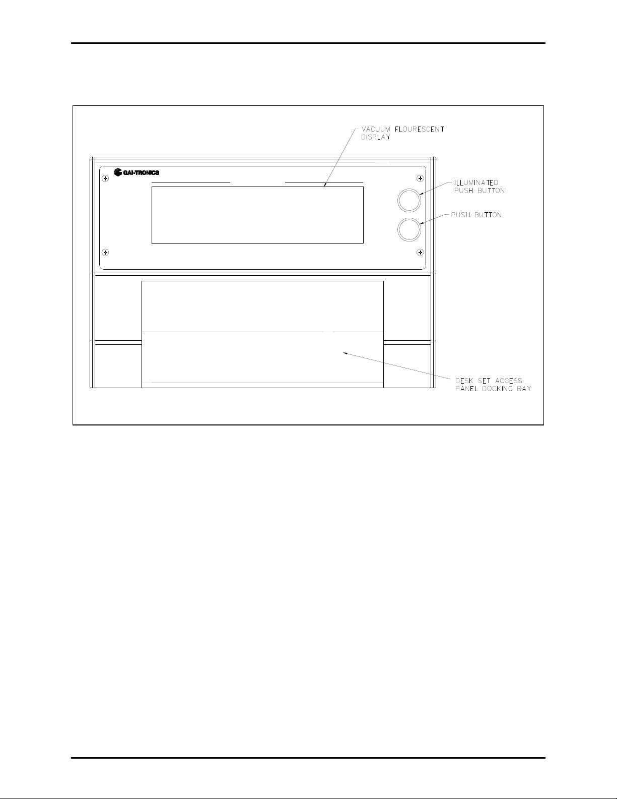
Vacuum fluorescent display (VFD)
Two configured push buttons, ACK/NEXT and PREV
Piezo alarm with volume control knob
When the Model 727-001 Desk Set Access Panel is connected to the Model 12576-500 Docking Station,
SmartSeries ADVANCE system activity can be monitored via the VFD. The piezo audible alarm is
typically used to alert personnel of updated system status.
The ACK/NEXT push button contains an LED that is pre-defined to provide system status information,
while the button has been pre-defined to acknowledge faults or to scroll to the next active fault in the
system. The PREV push button is pre-defined to allow the operator the ability to scroll to the previous
fault that has been acknowledged but is still active.
The piezo alarm and its associated volume control are located on the rear of the unit. The volume control
knob that allows the operator to adjust the output level of the piezo alarm from off to full.
GAI-Tronics Corporation 400 E. Wyomissing Ave. Mohnton, PA 19540 USA
610-777-1374 800-492-1212 Fax: 610-796-5954
V
ISIT WWW.GAI-TRONICS.COM FOR PRODUCT LITERATURE AND MANUALS
Page 2
Pub. 42004-691L2B
Model 12576-500 Desk Set Access Panel Docking Station with VFD Page 2 of 7
Hardware Configuration
SYSTEM STATUS
ACK/NEXT
PREV.
Figure 1. Model 12576-500 Docking Station
Interfaces
NOTE: All connections, except for the optional desk mic , are made to the rear of the docking station
instead of the rear of the desk set.
A 3-conductor ac power cord is included with the access panel. One end of the power cord is connected
to the 3-prong connector located on the back of the power supply, while the other end is plugged into a
grounded ac electrical outlet. The compatible ac input voltages are 120 V ac/240 V ac (auto-ranging),
50/60 Hz. The 5-pin DIN plug from the power supply is connected to the 5-pin DIN jack on the rear of
the access panel.
f:\standard ioms - current release\42004 instr. man uals\42004-691l2b.doc
02/13
Page 3
Pub. 42004-691L2B
Model 12576-500 Desk Set Access Panel Docking Station with VFD Page 3 of 7
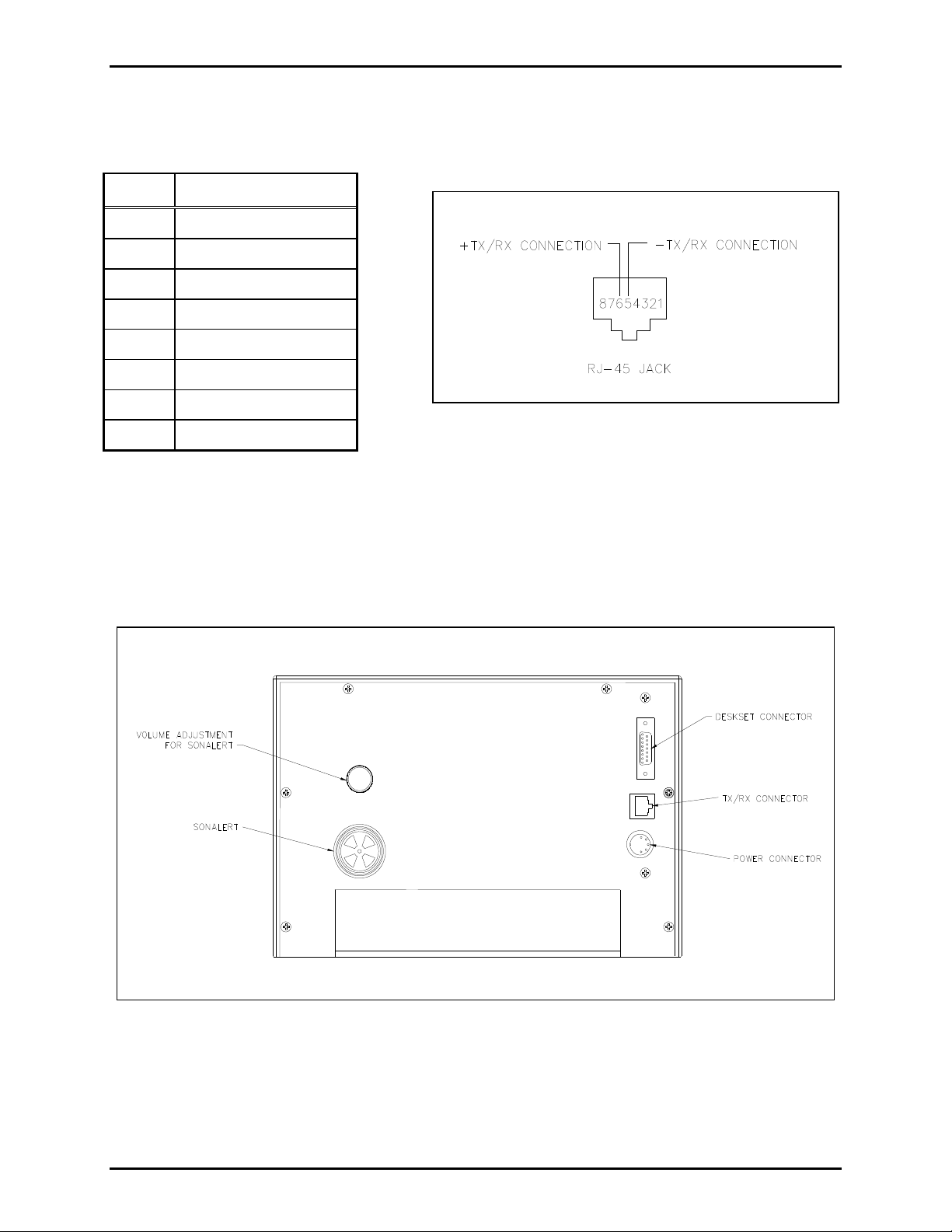
The data and audio connection to the system control unit is provided by an RJ-45 jack on the rear of the
access panel. The following are the physical connections of the RJ-45 jack:
Pin Connection
1 No connection
2 No connection
3 No connection
4 No connection
5 − TX/RX connection
6 + TX/RX connection
7 No connection
8 No connection
Figure 2.
The DB-15 connector on the rear of the docking station is used for connecting the desk set to the docking
station. This connection allows the user to connect the power and the data/audio connection to the rear of
the docking station to ease overall installation of the docking station. All of the data lines for the VFD
and the two push buttons are also combined into the DB-15 connection made to the desk set. If the
optional desk mic is used, the connection is still made at the rear of the desk set.
Figure 3. Model 12576-500 Docking Station Typical Connections (Rear View)
f:\standard ioms - current release\42004 instr. man uals\42004-691l2b.doc
02/13
Page 4

Pub. 42004-691L2B
Model 12576-500 Desk Set Access Panel Docking Station with VFD Page 4 of 7
Installation
WARNING
and in the installation manual.
1. Disconnect power before servicing.
2. Avoid servicing the unit during electrical storms.
3. Do not touch uninsulated wires.
Please adhere to all warnings, safety, and operating instructions on the unit
Mounting
Remove the docking station from its protective packing. Simply position the docking station on a sturdy
horizontal surface in a convenient location.
OTE: There are two #8-32 threaded inserts located on the bottom of the assembly that can be used to
N
anchor the assembly to a horizontal surface. The maximum screw penetration that is allowed from the
base of the docking station to the internal hardware is 0.375 inches (9.5 mm).
Data Connection
Connect the RJ-11 data cable from the RJ-45 jack on the rear of the docking station to the API connecting
block located in the ADVANCE control cabinet. If the 7-foot cable is not long enough, use a twisted-pair
cable terminated on one end with either a RJ-11 or RJ-45 plug. This connection is not polarity-sensitive
and may be wired in either orientation.
N
OTE: A 7-foot RJ-11 data cable is included with the desk set assembly.
Power
Connect the 3-conductor ac power cord provided with the docking station as follows:
1. Plug one end of the power cord into the 3-prong power connector at the rear of the power supply.
2. Plug the 5-pin DIN connector of the power supply into the 5-pin DIN jack on the rear of the docking
station.
3. Connect one end of the DB-15 cable to the desk set and slide the other end through the center of the
docking station, so that it is visible at the rear of the docking station.
4. If an optional desk mic has been purchased, slide the XLR plug on the end of the desk mic cable
through the center of the docking station and connect it to the desk set.
5. Set the desk set feet into the holes in the docking station allowing the desk set to lock into position.
6. Connect the other end of the DB-15 cable to the rear of the docking station.
7. Plug the power supply power cord into a grounded ac electrical outlet.
8. The assembly does not contain an integral power switch. The desk set access panel and docking
station will power up immediately.
f:\standard ioms - current release\42004 instr. man uals\42004-691l2b.doc
02/13
Page 5

Pub. 42004-691L2B
Model 12576-500 Desk Set Access Panel Docking Station with VFD Page 5 of 7
Operation
Operation of this assembly is highly dependent on the attached system’s software configuration. The
software is factory-created and subsequently downloaded to the associated ADVANCE system control
unit via an external PC at system start-up.
The docking station in conjunction with the desk set access panel offers several standard features in
addition to the ones that are listed in the desk set access panel’s manual. These include a VFD to provide
system status in a text format, a piezo alarm to alert a user of a change in system status, and two push
buttons that can be used to acknowledge and scroll through system faults listed on the VFD.
Va cuum Fluorescent Display (VFD ) and Control
The VFD displays status messages from the system control unit in a text format. Typically, the push
buttons to the right of the VFD are configured for NE XT and PREVIOUS functions. Use the NEXT
push button to view each additional new message. The NEXT push button can be configured to flash
when a new message is available. Use the PREVIOUS to cycle backward in order to review old status
messages.
Piezo Alarm
The piezo alarm is an audible indicator. It is typically configured to sound when a new message is
available on the VFD. If configured as described above, press the NEXT push button to display each new
message. When the last available new message has been displayed, the piezo alarm turns off. The exact
details of the operation of the piezo alarm are configurable. Located on the rear of the docking station is a
volume control knob that can be used to adjust the volume level of the piezo alarm from off to full on.
f:\standard ioms - current release\42004 instr. man uals\42004-691l2b.doc
02/13
Page 6

Pub. 42004-691L2B
Model 12576-500 Desk Set Access Panel Docking Station with VFD Page 6 of 7
How to Diagnose Assembly Faults
Servicing Guideli nes
1. Notify plant personnel of a system shutdown prior to servicing the unit.
2. Disconnect power before connecting external wiring or installing or removing the access panel.
Symptom Action
Access panel assembly does
not function. (No push
buttons detected, no LED
lamps activate, VFD is blank,
and handset is not
functioning.)
LEDS are blinking and
sounder is beeping.
ACK/NEXT and PREV push
buttons are not detected.
LED lamp for the
ACK/NEXT push button does
not activate.
Piezo alarm does not
function.
Verify ac power is applied to power supply. Verify that ac power
cord is plugged in. Also verify that ac outlet is active.
Verify that the LED is lit on top of the desktop power supply.
Verify that the data cable is properly connected between the
docking station and the control unit.
Call for service of the access panel.
Verify that the DB-15 cable is properly connected to both the desk
set and the docking station.
Verify that the DB-15 cable is properly connected to both the desk
set and the docking station.
Call for service of the access panel.
Verify that the DB-15 cable is properly connected to both the desk
set and the docking station.
Verify that an LED lamp is installed in the faulty illuminated push
button.
Replace the faulty LED lamp.
Call for service of the access panel.
Ensure that the piezo volume control is not turned all the way off.
Call for service of the access panel.
VFD does not function, even
during a lamp test.
f:\standard ioms - current release\42004 instr. man uals\42004-691l2b.doc
02/13
Call for service of the access panel.
Page 7

Pub. 42004-691L2B
Model 12576-500 Desk Set Access Panel Docking Station with VFD Page 7 of 7
Specification s
Electrical
Input voltage .................................................................................................................... 120 V ac/240 V ac
Auto-ranging
Input frequency ............................................................................................................................... 50/60 Hz
Input current draw .......................................................................................... 162 mA @ 120 V ac, nominal
290 mA @120 V ac, maximum
600 mA @120 V ac at startup
Note: This is the combined total current for the desk set and the docking station.
Environmental
Operating temperature range .................................................................. +32 F to +120 F (0 C to +49 C)
Relative humidity ................................................................................................ Non-condensing 85% max.
Mechanical
Unit dimensions ........................................11.06 W 13.61 L 7.44 D inches (281.0 345.7 189.1 mm)
Unit weight........................................................................................................................................ 4.75 lbs.
Docking Station material ............................................................................................................. Black ABS
External controls ................................................................................................................ Two push buttons
One LED
Piezo Alarm Volume Control
Speaker Volume Control Replacement Parts
Model Number Description
51002-209 Lens /LED Lamp Replacement
61002-007 Replacement Line Cord
61535-028 Replacement Communication Cable
Ref erence Material
Reference to Assembly/Model Drawings
Published
by
GAI-Tronics Model 12576-500 Desk Set Access Panel Docking Station Outline 73062
Title
GAI-Tronics
Ref. No.
f:\standard ioms - current release\42004 instr. man uals\42004-691l2b.doc
02/13
Page 8

Warranty
Equipment. GAI-Tronics warrants for a period of one (1) year from the date of shipment, that any
GAI-Tronics equipment supplied hereunder shall be free of defects in material and workmanship, shall
comply with the then-current product specifications and product literature, and if applicable, shall be fit
for the purpose specified in the agreed upon quotation or proposal document. If (a) Seller’s goods prove
to be defective in workmanship and/or material under normal and proper usage, or unfit for the purpose
specified and agreed upon, and (b) Buyer’s claim is made within the warranty period set forth above,
Buyer may return such goods to GAI-Tronics nearest depot repair facility, freight prepaid, at which time
they will be repaired or replaced, at Seller’s option, without charge to Buyer. Repair or replacement shall
be Buyer’s sole and exclusive remedy. The warranty period on any repaired or replacement equipment
shall be the greater of the ninety (90) day repair warranty or one (1) year from the date the original
equipment was shipped. In no event shall GAI-Tronics warranty obligations with respect to equipment
exceed 100% of the total cost of the equipment supplied hereunder. Buyer may also be entitled to the
manufacturer’s warranty on any third-party goods supplied by GAI-Tronics hereunder. The applicability
of any such third-party warranty will be determined by GAI-Tronics.
Services. Any services GAI-Tronics provides hereunder, whether directly or through subcontractors,
shall be performed in accordance with the standard of care with which such services are normally
provided in the industry. If the services fail to meet the applicable industry standard, GAI-Tronics will reperform such services at no cost to buyer to correct said deficiency to Company's satisfaction provided
any and all issues are identified prior to the demobilization of the Contractor's personnel from the work
site. Re-performance of services shall be Buyer's sole and exclusive remedy, and in no event shall GAITronics warranty obligations with respect to services exceed 100% of the total cost of the services
provided hereunder.
Warranty Periods. Every claim by Buyer alleging a defect in the goods and/or services provided
hereunder shall be deemed waived unless such claim is made in writing within the applicable warranty
periods as set forth above. Provided, however, that if the defect complained of is latent and not
discoverable within the above warranty periods, every claim arising on account of such latent defect shall
be deemed waived unless it is made in writing within a reasonable time after such latent defect is or
should have been discovered by Buyer.
Limitations / Exclusions. The warranties herein shall not apply to, and GAI-Tronics shall not be
responsible for, any damage to the goods or failure of the services supplied hereunder, to the extent
caused by Buyer’s neglect, failure to follow operational and maintenance procedures provided with the
equipment, or the use of technicians not specifically authorized by GAI-Tronics to maintain or service the
equipment. THE WARRANTIES AND REMEDIES CONTAINED HEREIN ARE IN LIEU OF AND
EXCLUDE ALL OTHER WARRANTIES AND REMEDIES, WHETHER EXPRESS OR IMPLIED BY
OPERATION OF LAW OR OTHERWISE, INCLUDING ANY WARRANTIES OF
MERCHANTABILITY OR FITNESS FOR A PARTICULAR PURPOSE.
Return Policy
If the equipment requires service, contact your Regional Service Center for a return authorization number
(RA#). Equipment should be shipped prepaid to GAI-Tronics with a return authorization number and a
purchase order number. If the equipment is under warranty, repairs or a replacement will be made in
accordance with the warranty policy set forth above. Please include a written explanation of all defects to
assist our technicians in their troubleshooting efforts.
Call 800-492-1212 (inside the USA) or 610-777-1374 (outside the USA) for help identifying the
Regional Service Center closest to you.
(Rev. 10/06)
 Loading...