

Page 1

Pub. 42004-636L2B
GAI-TRONICS® CORPORATION
A HUBBELL COMPANY
Model 12576-125
Access Panel with VFD
Confidential ity Notice
This manual is provided solely as an operation, installation, and maintenance guide and contains sensitive
business and technical information that is confidential and proprietary to GAI-Tronics. GAI-Tronics
retains all intellectual property and other rights in or to the information contained herein, and such
information may only be used in connection with the operation of your GAI-Tronics product or system.
This manual may not be disclosed in any form, in whole or in part, directly or indirectly, to any third party.
Introduction
The Model 12576-125 Access Panel is a component of the SmartSeries system that can be used for public
address, intercommunication, and emergency notification.
How to Use the Assembly
Application
The Model 12576-125 Access Panel is a standard EIA 19-inch rack-mount assembly with a 120 V ac/240
V ac power input. This power input allows the access panel to be used in almost all installations without
requiring additional line transformers.
The access panel can be used to initiate alarms, and to monitor system activity via a vacuum fluorescent
display (VFD). A piezo audible alarm is included, which is typically used to alert personnel of updated
system status. The panel provides a handset equipped with an integral pressbar. The handset is used to
make page announcements and to hold two-way party line conversations.
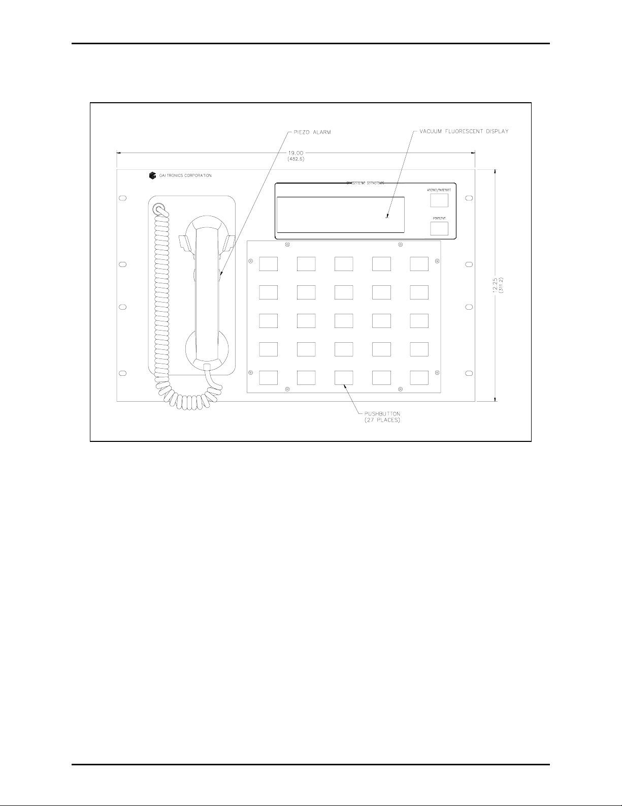
The main components of the Model 12576-125 Access Panel are as follows:
• Vacuum fluorescent display
• 27 push buttons
• Handset
• Piezo alarm
The function of each of the 27 push buttons is software configurable. Contact GAI-Tronics for more
information on configuration of the access panel.
Of the 27 push buttons, 23 contain an LED lamp that can be configured to provide system status
information. The four remaining push buttons, including the lower push button to the right of the VFD
and the lower three push buttons in the rightmost column of five switches, contain non-functional LEDs.
These non-functional LEDs may be used as spares.
GAI-Tronics Corporation 400 E. Wyomissing Ave. Mohnton, PA 19540 USA
610-777-1374 800-492-1212 Fax: 610-796-5954
V
ISIT WWW.GAI-TRONICS.COM FOR PRODUCT LITERATURE AND MANUALS
Page 2
Pub. 42004-636L2B
Model 12576-125 Access Panel with VFD Page: 2 of 8
Hardware Configuration
Figure 1. Model 12576-125 Access Panel (Front View)
f:\standard ioms - current release\42004 instr. manuals\42004-636l2b.doc
11/10
Page 3
Pub. 42004-636L2B
Model 12576-125 Access Panel with VFD Page: 3 of 8
Interfaces
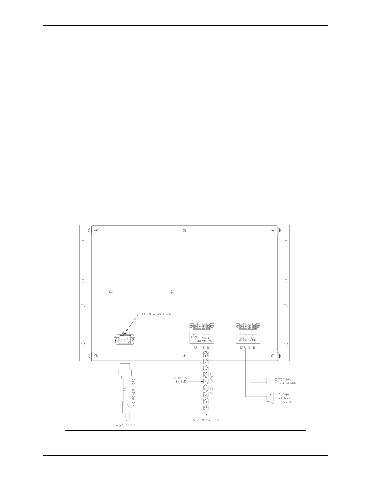
A three-conductor ac power cord is included with the access panel. One end of the power cord is
connected to the three-prong connector located on the back of the access panel, while the other end is
plugged into a grounded ac electrical outlet . The compati ble ac inpu t vo ltag es are 120 V ac /240 V ac
(auto-ranging), 50/60 Hz.
Data and audio connection to the system control unit is provided by a four-position terminal block located
at the rear of the panel. The physical connection is a single twisted-pair cable connection using two of the
four terminal points. One of the remaining two points is tied to chassis ground and may be used to
connect to a cable shield if shielded cable is pre ferred.
OTE: Ensure that only one end of the cable’s shield is grounded in order to avoid ground loops. The
N
remaining terminal point is not used.
A second four-position terminal block is provided for optional connections:
• Two terminals are available to connect a single 40-ohm (nominal) external speaker for page audio
monitoring.
• Two terminals are available to drive an external piezo alarm.
Contact GAI-Tronics Service Department for further information.
OTE: The piezo alarm is a polarity-sensitive device. Ensure that proper polarity is observed when
N
connecting it to the access panel.
Figure 2. Model 12576-125 Access Panel Typical Connections (Rear View)
f:\standard ioms - current release\42004 instr. manuals\42004-636l2b.doc
11/10
Page 4

Pub. 42004-636L2B
Model 12576-125 Access Panel with VFD Page: 4 of 8
Installation
WARNING
Please adhere to all warnings, safety, and operating instructions on the unit and in the installation
manual.
1. Disconnect power before servicing.
2. Avoid servicing the unit during electrical storms.
3. Do not touch uninsulated wires.
Mounting
NOTE: Mounting hardware is not included with this assembly and must be purchased separately.
Remove the access panel from its protective packing. Position the access panel in the 19-inch EIA
enclosure and secure it with the appropriate screws. When installed correctly, the handset will be on the
left side of the access panel.
Data Connection
Connect a twisted-pair cable from the access panel terminal block points labeled VOICE/DATA COM. to
the corresponding connector on the appropriate termination block of the control unit. This connection is
not polarity-sensitive and may be wired in either orientation. A chassis ground (labeled E-GND) is also
provided on this terminal block to connect to a cable shield, if shielded cable is used.
OTES:
N
1. The data cable is not included with this assembly and must be purchased separately.
2. If shielded cable is used, only one
ground loops.
end of the cable’s shield should be grounded in order to avoid
External Speaker Connection
Connect the optional external 40-ohm speaker to the access panel at the terminal block points labeled
SPKR+/- at the back of the unit. Contact GAI-Tronics Service Department for further information.
N
OTE: The optional external speaker is not included with this assembly and must be purchased
separately.
External Piezo Alarm Connection
Connect the optional external piezo alarm to the access panel at the terminal block points labeled PIEZO
ALARM+/- at the back of the unit. Contact GAI-Tronics Service Department for further information.
OTES:
N
1. The optional external piezo alarm is not included with this assembly and must be purchased
separately.
2. The external piezo alarm is a polarity-sensitive device and care must be taken to ensure that proper
polarity is observed when connecting it to the access panel.
f:\standard ioms - current release\42004 instr. manuals\42004-636l2b.doc
11/10
Page 5

Pub. 42004-636L2B
Model 12576-125 Access Panel with VFD Page: 5 of 8
Power
Connect the three-conductor ac power cord prov ide d with the access pane l as follo ws:
1. Loosen the captive screw on the connector lock of the three-prong power connector at the rear of the
access panel.
2. Plug one end of the power cord into the three-prong power connector at the rear of the access panel.
3. Tighten the captive screw in order to clamp the connector lock around the power cord. Plug the other
end into a grounded ac electrical outlet.
4. The access panel does not contain an internal power switch. The access panel will power up
immediately.
Push Button Overlay
To install or replace the push button overlay, proceed as follows:
1. Loosen the eight mounting screws located along the edge of the existing push button overlay using a
1/16-inch Allen wrench or equivalent. Save these mounting screws.
2. Lift the existing push button overlay away from the access panel.
3. Mount the new push button overlay onto the access panel, aligning the screw-holes on the overlay
with those on the access panel.
4. Replace and tighten the eight mounting screws using a 1/16-inch Allen wrench or equivalent.
f:\standard ioms - current release\42004 instr. manuals\42004-636l2b.doc
11/10
Page 6

Pub. 42004-636L2B
Model 12576-125 Access Panel with VFD Page: 6 of 8
Operation
Operation of this assembly is highly dependent on the attached system’s software configuration. The
software is factory-created and sub sequ ently downloaded to the system control unit via an external PC at
system start-up.
This access panel offers the following standard features in addition to the configurable features. The
standard features include a handset used for page and party functions, a vacuum fluorescent display
(VFD) used to provide system status in a text format, and a piezo alarm that can be activated to alert a
user of a change in system status.
Handset Communications
The handset is used for both page and party communications. Lifting the handset from the cradle creates
an off-hook condition. In a normal configuration, lifting the handset causes it to be connected to a party
line.
Va cuum Fluorescent Display (VFD ) and Control
The VFD displays status messages from the system control unit in a text format. Typically, the push
buttons to the right of the VFD are configured for NE XT and PREVIOUS functions. Use the NEXT
push button to view each additional new message. The NEXT push button can be configured to flash
when a new message is available. Use the PREVIOUS to cycle backward in order to review old status
messages.
Piezo Alarm
The piezo alarm is an audible indicator. It is typically configured to sound when a new message is
available on the VFD. If configured as described above, press the NEXT push button to display each new
message. When the last available new message has been displayed, the piezo alarm turns off. The exact
details of the operation of the piezo alarm are configurable.
f:\standard ioms - current release\42004 instr. manuals\42004-636l2b.doc
11/10
Page 7

Pub. 42004-636L2B
Model 12576-125 Access Panel with VFD Page: 7 of 8
How to Diagnose Assembly Faults
Servicing Guideli nes
1. Notify plant personnel of a system shutdown prior to servicing the unit.
2. Disconnect power before connecting external wiring or installing or removing the access panel.
Symptom Action
Access panel does not
function. (No push buttons
detected, no LED lamps
activate, VFD is blank, and
handset is not functioning.)
No push buttons are detected.
Some push buttons are not
detected.
No LED lamps activate.
Some LED lamps do not
activate.
Piezo alarm does not function.
• Verify ac power is applied to access panel. Verify that ac power
cord is plugged in. Also verify that ac outlet is active.
• Verify that the twisted-pair data cable is properly connected between
the access panel and the control unit.
• Call for service of the access panel.
• Verify that the twisted-pair data cable is properly connected between
the access panel and the control unit.
• Call for service of the access panel.
Call for service of the access panel.
• Verify that the twisted-pair data cable is properly connected between
the access panel and the control unit.
• Call for service of the access panel.
• Verify that none of the potentially faulty LED lamps are in the set of
4 inactive LED lamps (the 3 lower LED lamps located in the
rightmost column and the lower LED lamp to the right of the VFD.)
• Verify that an LED lamp is installed in the faulty illuminated push
button(s).
• Replace the faulty LED lamp(s).
• Call for service of the access panel.
Call for service of the access panel.
VFD does not function, even
during a lamp test.
Handset does not function
properly.
External speaker interface does
not function.
f:\standard ioms - current release\42004 instr. manuals\42004-636l2b.doc
11/10
Call for service of the access panel.
Call for service of the access panel.
• Verify wiring between the speaker connector on the access panel
and the speaker itself.
• Determine if speaker is faulty by connecting a different speaker to
the speaker interface and verifying operation.
• Call for service of the access panel.
Page 8

Pub. 42004-636L2B
Model 12576-125 Access Panel with VFD Page: 8 of 8
Specification s
Electrical
Input voltage..................................................................................................................... 120 V ac/240 V ac
Auto-ranging
Input frequency................................................................................................................................ 50/60 Hz
Input current draw.................................................................................................... 1 amp max. @ 120 V ac
Line length....................................................................3.0 km with No. 24 AWG, attenuation = 8.0 dB/km
2.2 km with No. 26 AWG, attenuation = 11.5 dB/km
Environmental
Operating temperature range.................................................................. +32° F to +120 °F (0° C to +49° C)
Relative humidity.................................................................................................Non-condensing 85% max.
Mechanical
Unit dimensions.......................................12.25 H × 19.00 W × 9.13 D inches (311.2 × 482.6 × 232.2 mm)
Unit weight.........................................................................................................................................12.9 lbs.
Handset material...........................................................................................................................Black ABS
Handset microphone..............................................................................................Dynamic, noise-canceling
Handset receiver..............................................................Dynamic, hearing aid compatible per FCC part 68
Handset cord....................................................................................... Hytrel, 6-foot (1.8 m) when extended
Handset cradle............................................................................................Fixed. Built-in off-hook detector
External controls............................................................................................................Press-to-page switch
27 configurable push buttons
Approval
CE Mark
Replacements Par ts
Model Number Description
12509-009 LED Lamp Replacement Kit
54003-001 LED Lamp Holder Tool
54003-002 Lens Removal Tool
61002-007 Replacement Line Cord
Ref erence Material
Reference to Assembly/Model Drawings
Published by Title GAI-Tronics Ref. No.
GAI-Tronics Model 12576-125 Access Panel Outline 72121
f:\standard ioms - current release\42004 instr. manuals\42004-636l2b.doc
11/10
Page 9

Warranty
Equipment. GAI-Tronics warrants for a period of one (1) year from the date of shipment, that any
GAI-Tronics equipment supplied hereunder shall be free of defects in material and workmanship, shall
comply with the then-current product specifications and product literature, and if applicable, shall be fit
for the purpose specified in the agreed-upon quotation or proposal document. If (a) Seller’s goods prove
to be defective in workmanship and/or material under normal and proper usage, or unfit for the purpose
specified and agreed upon, and (b) Buyer’s claim is made within the warranty period set forth above,
Buyer may return such goods to GAI-Tronics’ nearest depot repair facility, freight prepaid, at which time
they will be repaired or replaced, at Seller’s option, without charge to Buyer. Repair or replacement shall
be Buyer’s sole and exclusive remedy. The warranty period on any repaired or replacement equipment
shall be the greater of the ninety (90) day repair warranty or one (1) year from the date the original
equipment was shipped. In no event shall GAI-Tronics warranty obligations with respect to equipment
exceed 100% of the total cost of the equipment supplied hereunder. Buyer may also be entitled to the
manufacturer’s warranty on any third-party goods supplied by GAI-Tronics hereunder. The applicability
of any such third-party warranty will be determined by GAI-Tronics.
Services. Any services GAI-Tronics provides hereunder, whether directly or through subcontractors,
shall be performed in accordance with the standard of care with which such services are normally
provided in the industry. If the services fail to meet the applicable industry standard, GAI-Tronics will
re-perform such services at no cost to buyer to correct said deficiency to Company's satisfaction provided
any and all issues are identified prior to the demobilization of the Contractor’s personnel from the work
site. Re-performance of services shall be Buyer’s sole and exclusive remedy, and in no event shall GAITronics warranty obligations with respect to services exceed 100% of the total cost of the services
provided hereunder.
Warranty Periods. Every claim by Buyer alleging a defect in the goods and/or services provided
hereunder shall be deemed waived unless such claim is made in writing within the applicable warranty
periods as set forth above. Provided, however, that if the defect complained of is latent and not
discoverable within the above warranty periods, every claim arising on account of such latent defect shall
be deemed waived unless it is made in writing within a reasonable time after such latent defect is or
should have been discovered by Buyer.
Limitations / Exclusions. The warranties herein shall not apply to, and GAI-Tronics shall not be
responsible for, any damage to the goods or failure of the services supplied hereunder, to the extent
caused by Buyer’s neglect, failure to follow operational and maintenance procedures provided with the
equipment, or the use of technicians not specifically authorized by GAI-Tronics to maintain or service the
equipment. THE WARRANTIES AND REMEDIES CONTAINED HEREIN ARE IN LIEU OF AND
EXCLUDE ALL OTHER WARRANTIES AND REMEDIES, WHETHER EXPRESS OR IMPLIED BY
OPERATION OF LAW OR OTHERWISE, INCLUDING ANY WARRANTIES OF
MERCHANTABILITY OR FITNESS FOR A PARTICULAR PURPOSE.
Return Policy
If the equipment requires service, contact your Regional Service Center for a return authorization number
(RA#). Equipment should be shipped prepaid to GAI-Tronics with a return authorization number and a
purchase order number. If the equipment is under warranty, repairs or a replacement will be made in
accordance with the warranty policy set forth above. Please include a written explanation of all defects to
assist our technicians in their troubleshooting efforts.
Call 800-492-1212 (inside the USA) or 610-777-1374 (outside the USA) for help identifying the
Regional Service Center closest to you.
(Rev. 10/06)
 Loading...