

Page 1
Pub. 42003-263B
GAI-TRONICS® CORPORATION
A HUBBELL COMPANY
VoIP and VoIP WiFi T e lephone PCBA
Replacement Kits
Models 12565-701, -702, & -802
Confidential ity Notice
This manual is provided solely as an operational, installation, and maintenance guide and contains
sensitive business and technical information that is confidential and proprietary to GAI-Tronics.
GAI-Tronics retains all intellectual property and other rights in or to the information contained herein,
and such information may only be used in connection with the operation of your GAI-Tronics product or
system. This manual may not be disclosed in any form, in whole or in part, directly or indirectly, to any
third party.
General Information
The Model 12565-701, -702, and -802 VoIP and VoIP WiFi Replacement Kits contain two
interconnected circuit board assemblies (Carrier and VoIP) which serve as replacement for the PCB
assemblies found in the GAI-Tronics VoIP Telephones listed in Table 1 below.
Table 1. Model Chart
Kit Model Applies to GAI-Tronics Telephones:
12565-701 226-700, 246-700, 256-700, and 276-700 VoIP Telephones
12565-702 393-700, 393AL-700, 394AL-702, 397-700, 397-701, 398-701, and 398-702 VoIP
Hands-free Telephones
12565-802 393-800A, 393AL-800A, 394AL-802A, 397-800A, 398-801A, and 398-802A VoIP
WiFi Hands-free Telephones
Electrostatic Discharge (ESD) Protection:
Your telephone may have an earth ground terminal provision. If so, ensure that it is connected to ground
in accordance with all local safety regulations and the National Electrical Code (NEC). Grounding has to
be ensured for safe and stable communications. Do not use long and coiled ground wires. Trim ground
wires to the required length. Use a star configuration whenever possible.
GAI-Tronics Corporation 400 E. Wyomissing Ave. Mohnton, PA 19540 USA
610-777-1374 800-492-1212 Fax: 610-796-5954
V
ISIT WWW.GAI-TRONICS.COM FOR PRODUCT LITERATURE AND MANUALS
Page 2
Pub. 42003-263B
ODEL 12565-701, -702, & -802 VOIP & VOIP WIFI TELEPHONE PCBA REPLACEMENT KITS Page 2 of 16
M
Installation
Model 226-700
Removing the Old PCBA Assembly
1. Use the Model 233-001 Security Screwdriver to remove the eight front panel screws and remove the
panel from the enclosure after disconnecting the Cat5 or CatE5 cable from the VoIP Circuit PCBA.
2. Disconnect the handset, hookswitch, volume control push button, keypad, and ringer cables from the
PCBA.
3. Disconnect any optional (input/output) cables from the PCBA.
4. Depress the locking tab on each nylon standoff while lifting up on the corner of the PCBA to remove
it.
Installing the New PCBA
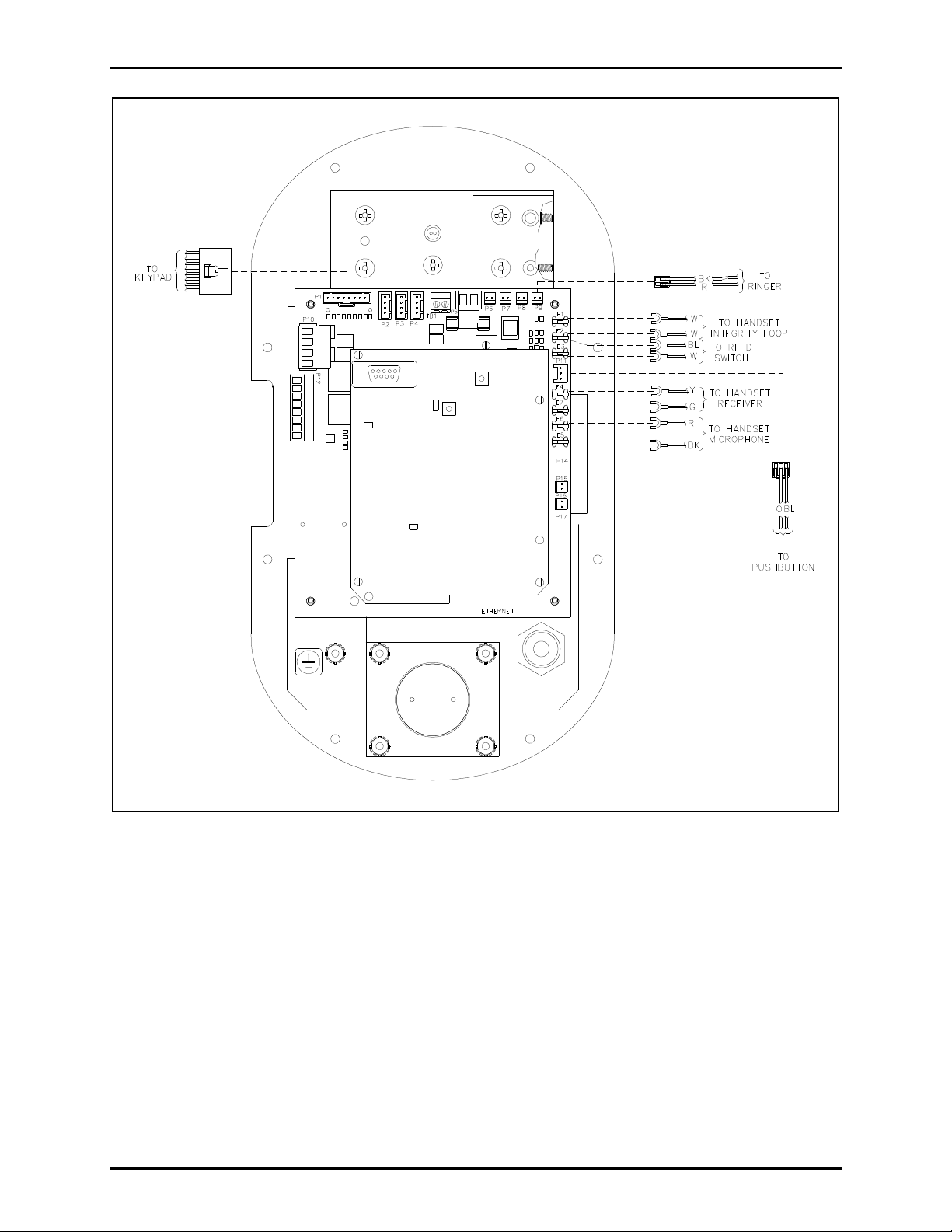
1. Align the holes of the new PCBA with the snap-on nylon standoffs in the telephone, maintaining
proper orientation. Refer to Figure 1 as an example.
2. Press firmly on each corner of the PCBA to lock the standoffs.
3. Reconnect the handset, hookswitch, volume control push button, keypad, and ringer cables to the
PCBA. Refer to Figure 1.
4. Reconnect any optional (input/output) cables from the PCBA.
5. Use the Model 233-001 Security Screwdriver to install the eight front panel screws.
OTE: For Model 226-700 VoIP Telephones purchased prior to December 2013, the ringer assembly and
N
volume control push button assembly must be replaced for proper operation when the PCBAs in this kit
are replaced.
f:\standard ioms - current release\42003 kit manuals \42003-263b. doc
02/15
Page 3
Pub. 42003-263B
ODEL 12565-701, -702, & -802 VOIP & VOIP WIFI TELEPHONE PCBA REPLACEMENT KITS Page 3 of 16
M
Figure 1. Model 226-700
f:\standard ioms - current release\42003 kit manuals \42003-263b. doc
02/15
Page 4

Pub. 42003-263B
ODEL 12565-701, -702, & -802 VOIP & VOIP WIFI TELEPHONE PCBA REPLACEMENT KITS Page 4 of 16
M
Models 246-700 and 256-700
Removing the Old PCBA Assembly
1. Use a Phillips screwdriver to remove the four front panel screws and remove the panel from the
enclosure after disconnecting the Ethernet cable.
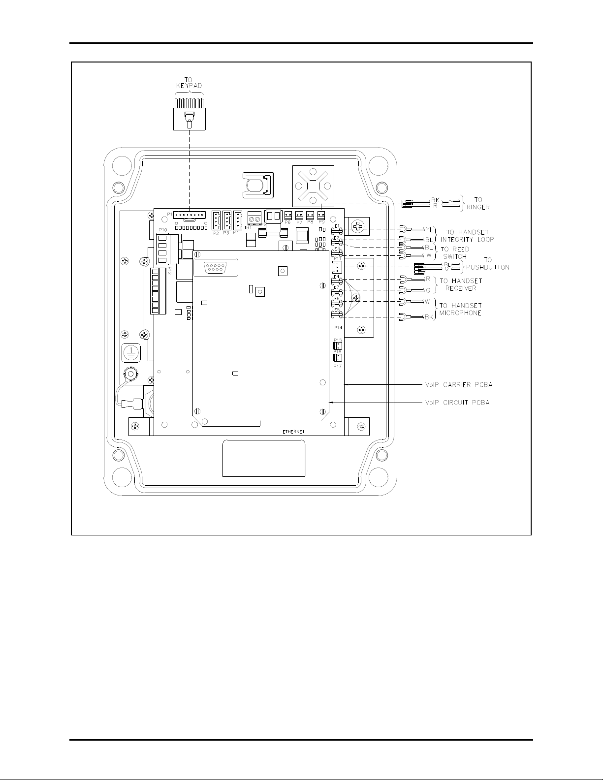
2. Disconnect the handset, hookswitch, push button, keypad, and ringer cables from the VoIP Carrier
PCBA. Record the location of each connection for later reconnection. See Figure 2.
3. Depress the locking tab on each nylon standoff while lifting up that corner of the PCBA to remove it.
4. Clip any tie wraps securing the wires together.
Installing the New PCBA
1. Align the holes of the new PCBA with the snap-on nylon standoffs in the telephone. Refer to Figure
2 for correct PCBA orientation.
2. Press firmly on each corner of the PCBA to lock in the standoffs.
3. Reconnect the Ethernet cable.
4. Refer to Figure 2 for locations of the connectors on the new PCBA.
5. Secure wires as before using the tie wraps provided.
6. Use a Philips screwdriver to install the four front panel screws.
OTE: For Model 246-700 and 256-700 VoIP Telephones purchased prior to December 2013, the ringer
N
assembly and volume control push button assembly must be replaced for proper operation when the
PCBAs in this kit are replaced.
f:\standard ioms - current release\42003 kit manuals \42003-263b. doc
02/15
Page 5
Pub. 42003-263B
M
ODEL 12565-701, -702, & -802 VOIP & VOIP WIFI TELEPHONE PCBA REPLACEMENT KITS Page 5 of 16
Figure 2. Models 246-70
f:\standard ioms - cur rent release\4 2003 kit manuals\42003-263b.doc
02/15
0/ 256-700
Page 6
Pub. 42003-263B
ODEL 12565-701, -702, & -802 VOIP & VOIP WIFI TELEPHONE PCBA REPLACEMENT KITS Page 6 of 16
M
Model 276-700
Removing the Old PCBA Assembly
1. Use the Model 233-001 Security Screwdriver to remove the six front panel screws and remove the
panel from the enclosure after disconnecting the Cat5 or Cat5e cable from the VoIP Circuit PCBA.
2. Disconnect the handset, hookswitch, volume control push button, keypad, and ringer cables form the
PCBA.
3. Disconnect any optional (input/output) cables from the PCBA.
4. Depress the locking tab on each nylon standoff while lifting up on the corner of the PCBA to remove
it.
Installing the New PCBA
1. Align the holes of the new PCBA with the snap-on nylon standoffs in the telephone, maintaining
proper orientation. Refer to Figure 3 as an example.
2. Press firmly on each corner of the PCBA to lock the standoffs.
3. Reconnect the handset, hookswitch, volume control push button, keypad, and ringer cables to the
PCBA. Refer to Figure 3.
4. Reconnect the Cat5 or Cat5e cable to the VoIP Circuit PCBA. Refer to Figure 3.
5. Reconnect any optional (input/output) cables from the PCBA.
6. Use the Model 233-001 Security Screwdriver to install the six front panel screws.
OTE: For Model 276-700 VoIP Telephones purchased prior to December 2013, the ringer assembly and
N
volume control push button assembly must be replaced for proper operation when the PCBAs in this kit
are replaced.
f:\standard ioms - current release\42003 kit manuals \42003-263b. doc
02/15
Page 7

Pub. 42003-263B
ODEL 12565-701, -702, & -802 VOIP & VOIP WIFI TELEPHONE PCBA REPLACEMENT KITS Page 7 of 16
M
Figure 3. Model 276-700
f:\standard ioms - current release\42003 kit manuals \42003-263b. doc
02/15
Page 8

Pub. 42003-263B
ODEL 12565-701, -702, & -802 VOIP & VOIP WIFI TELEPHONE PCBA REPLACEMENT KITS Page 8 of 16
M
Models 393-700, 393AL-700 and 394AL-702
Removing the Old PCBA Assembly
1. Use the Model 233-001 Security Screwdriver to remove the four front cover screws, and remove the
front cover after disconnecting the Ethernet cable and ground wire, if applicable.
2. Disconnect the microphone, speaker, LED indicator, and push-button switch cables from the PCBA.
OTE: For Model 394AL-702 there will also be a second push-button switch connection and a
N
keypad cable connection. Record the location of each connection for later reconnection.
See Figure 4.
3. Unscrew the four screws securing the PCBA. Save the screws for later reassembly.
4. If necessary, clip any tie wraps securing the wires together.
Installing the New PCBA
1. Align the holes in the four corners of the new PCBA with the standoffs in the telephone, maintaining
proper orientation. See Figure 4.
2. Use the screws (from step 3 in the previous section) to secure the PCBA.
3. Reconnect the microphone, speaker, LED indicator, and push-button switch cable.
NOTE: For Model 394AL-702, there will also be a second push-button switch connection and a
keypad cable connection.
4. Secure wires as before using the tie wraps provided.
5. Reconnect the Ethernet cable and ground wire, if applicable.
6. Use the Model 233-001 Security Screwdriver to install the four front cover screws.
f:\standard ioms - current release\42003 kit manuals \42003-263b. doc
02/15
Page 9

Pub. 42003-263B
ODEL 12565-701, -702, & -802 VOIP & VOIP WIFI TELEPHONE PCBA REPLACEMENT KITS Page 9 of 16
M
Figure 4.
f:\standard ioms - current release\42003 kit manuals \42003-263b. doc
02/15
Page 10

Pub. 42003-263B
ODEL 12565-701, -702, & -802 VOIP & VOIP WIFI TELEPHONE PCBA REPLACEMENT KITS Page 10 of 16
M
Models 397-700, 397-701, 398-701, and 398-702
Removing the Old PCBA
1. Use the Model 233-001 Security Screwdriver to remove the six front panel screws, and remove the
front cover after disconnecting the Ethernet cable, ground wire and any applicable external cables to
the PCBA, input/output, or local power connections. See Figure 5 and Figure 9.
2. Disconnect the microphone, speaker, LED indicator, and push-button switch cables from the PCBA.
a. Model 397-701: There will also be a second push-button switch cable.
b. Model 398-701: There will also be a keypad cable connection.
c. Model 398-702: There will be a second push-button switch cable and a keypad cable connection.
Record the location of each connection for later reconnection. See Figure 5.
3. Unscrew the four screws securing the PCBA. Save the screws for later reassembly.
4. If necessary, clip any tie wraps securing the wires together.
Installing the New PCBA
1. Align the holes in the four corners of the new PCBA with the standoffs in the telephone, m ain ta ining
proper orientation. See Figure 5.
2. Use the screws (from step 3 in previous section) to secure PCBA.
3. Reconnect the microphone, speaker, LED indicator and push-button swi tch cable.
Make note in step 2 above of any additional connections for each model.
4. Reconnect the Ethernet cable, ground wire and any additional external wires. Refer to Figure 9 on
page 16.
5. Secure wires as before using the tie wraps provided.
6. Use the Model 233-001 Security Screwdriver to install the six front cover screws.
f:\standard ioms - current release\42003 kit manuals \42003-263b. doc
02/15
Page 11

Pub. 42003-263B
ODEL 12565-701, -702, & -802 VOIP & VOIP WIFI TELEPHONE PCBA REPLACEMENT KITS Page 11 of 16
M
Figure 5.
f:\standard ioms - current release\42003 kit manuals \42003-263b. doc
02/15
Page 12

Pub. 42003-263B
ODEL 12565-701, -702, & -802 VOIP & VOIP WIFI TELEPHONE PCBA REPLACEMENT KITS Page 12 of 16
M
Models 393-800A, 393AL-800A and 394AL-802A
Removing the Old PCBA Assembly
1. Use the Model 233-001 Security Screwdriver to remove the four front cover screws.
2. For Models 393AL-800A and 394AL-802A, gently pull the front cover away from the back box.
Disconnect the antenna cable from the antenna connection mounted on the PCBA. See Figure 6.
3. Disconnect ground wire.
4. Disconnect the microphone, speaker, LED indicator, and push-button switch cables from the PCBA.
NOTE: For Model 394AL-702, there will also be a second push-button switch connection and a
keypad cable connection. Record the location of each connection for later reconnection. See Figure
6.
5. Unsnap the U.FL connection from the WiFi Module on the Carrier PCBA. Unplug the Cat5 cable
from the J2 connector on the carrier PCBA. Remove the two screws securing the bracket with the RF
cable assembly mounted to it from the Carrier PCBA, and set aside for later reassembly.
N
OTE: For Model 393-800A, the antenna is attached to this bracket/cable assembly. See Figure 7.
6. Unscrew the three remaining screws securing the PCBA. Save all the screws for later reass e m b ly .
7. If necessary, clip any tie wraps securing the wires together.
Installing the New PCBA
1. Align the holes in the four corners of the new PCBA with the standoffs in the telephone, m ain ta ining
proper orientation. See Figure 6. Unplug the Cat5 cable from the J2 connector on the carrier PCBA.
2. Reattach the bracket with the RF cable assembly (with antenna for the Model 393-800A) to the lower
left hand corner of the PCBA. Plug the Cat5 Cable into J2 on the carrier PCBA.
3. Use the screws (from step 6 in previous section) to secure PCBA.
4. Secure wires as before using the tie wraps provided.
5. Snap the U.FL connector to the WiFi module located on the carrier PCBA.
6. Reconnect the microphone, speaker, LED indicator and push-button swi tch cable.
N
OTE: For Model 394AL-702 there will also be a second push-button switch connection and a
keypad cable connection.
7. For Models 393AL-800A and 394AL-802A reconnect the antenna cable and ground wire.
8. Use the Model 233-001 Security Screwdriver to install the four front cover screws.
f:\standard ioms - current release\42003 kit manuals \42003-263b. doc
02/15
Page 13

Pub. 42003-263B
ODEL 12565-701, -702, & -802 VOIP & VOIP WIFI TELEPHONE PCBA REPLACEMENT KITS Page 13 of 16
M
Figure 6.
f:\standard ioms - current release\42003 kit manuals \42003-263b. doc
02/15
Figure 7.
Page 14

Pub. 42003-263B
ODEL 12565-701, -702, & -802 VOIP & VOIP WIFI TELEPHONE PCBA REPLACEMENT KITS Page 14 of 16
M
Models 397-800A, 397-801A, 398-801A, and 398-802A
Removing the Old PCBA
1. Use the Model 233-001 Security Screwdriver to remove the six front panel screws, and remove the
front cover after disconnecting the ground wire and any applicable external cables to the PCBA,
antenna cable, input/output or local power connections. Refer to Figure 9 on page 16.
2. Disconnect the microphone, speaker, LED indicator, and push-button switch cables from the PCBA.
a. Model 397-801A: There will also be a second push-button switch cable.
b. Model 398-801A: There will also be a keypad cable connection.
c. Model 398-802A: There will be a second push-button switch cable and a keypad cable
connection. Record the location of each connection for later reconnection. See Figure 8.
3. Unsnap the U.FL connection from the WiFi Module on the Carrier PCBA. Unplug the Cat5 cable
from the J2 connector on the Carrier PCBA. Remove the two screws securing the bracket with the
RF cable assembly mounted to it from the carrier PCBA. Set aside for later reassembly.
4. Unscrew the three remaining screws securing the PCBA. Save the screws for later reassembly.
5. If necessary, clip any tie wraps securing the wires together.
Installing the New PCBA
1. Align the holes in the four corners of the new PCBA with the standoffs in the telephone, m ain ta ining
proper orientation.
2. Unplug the Cat5 cable from the J2 connector on the carrier PCBA. See Figure 8.
3. Reattach the bracket with the RF cable assembly to the lower left hand corner of the PCBA. Plug the
Cat5 cable into J2 on the carrier PCBA.
4. Use the screws (from step 3 in previous section) to secure PCBA.
5. Snap the U.FL connector to the WiFi Module located on the Carrier PCBA.
6. Secure wires as before using the tie wraps provided.
7. Reconnect the microphone, speaker, LED indicator and push-button switch cable. Note in step 2 of
the previous section the additional connections for each model. See Figure 8.
8. Use the screws (from step 4 in previous section) to secure PCBA.
9. Reconnect the ground wire and any external connections previously used.
10. Use the Model 233-001 Security Screwdriver to install the six front cover screws.
f:\standard ioms - current release\42003 kit manuals \42003-263b. doc
02/15
Page 15

Pub. 42003-263B
ODEL 12565-701, -702, & -802 VOIP & VOIP WIFI TELEPHONE PCBA REPLACEMENT KITS Page 15 of 16
M
f:\standard ioms - current release\42003 kit manuals \42003-263b. doc
02/15
Figure 8.
Page 16

Pub. 42003-263B
ODEL 12565-701, -702, & -802 VOIP & VOIP WIFI TELEPHONE PCBA REPLACEMENT KITS Page 16 of 16
M
Figure 9. VoIP/WiFi shown
(VoIP has the same input/output and local power connections)
f:\standard ioms - current release\42003 kit manuals \42003-263b. doc
02/15
Page 17

Warranty
Equipment. GAI-Tronics warrants for a period of one (1) year from the date of shipment, that any
GAI-Tronics equipment supplied hereunder shall be free of defects in material and workmanship, shall
comply with the then-current product specifications and product literature, and if applicable, shall be fit
for the purpose specified in the agreed-upon quotation or proposal document. If (a) Seller’s goods prove
to be defective in workmanship and/or material under normal and proper usage, or unfit for the purpose
specified and agreed upon, and (b) Buyer’s claim is made within the warranty period set forth above,
Buyer may return such goods to GAI-Tronics’ nearest depot repair facility, freight prepaid, at which time
they will be repaired or replaced, at Seller’s option, without charge to Buyer. Repair or replacement shall
be Buyer’s sole and exclusive remedy. The warranty period on any repaired or replacement equipment
shall be the greater of the ninety (90) day repair warranty or one (1) year from the date the original
equipment was shipped. In no event shall GAI-Tronics warranty obligations with respect to equipment
exceed 100% of the total cost of the equipment supplied hereunder. Buyer may also be entitled to the
manufacturer’s warranty on any third-party goods supplied by GAI-Tronics hereunder. The applicability
of any such third-party warranty will be determined by GAI-Tronics.
Services. Any services GAI-Tronics provides hereunder, whether directly or through subcontractors,
shall be performed in accordance with the standard of care with which such services are normally
provided in the industry. If the services fail to meet the applicable industry standard, GAI-Tronics will
re-perform such services at no cost to buyer to correct said deficiency to Company's satisfaction provided
any and all issues are identified prior to the demobilization of the Contractor’s personnel from the work
site. Re-performance of services shall be Buyer’s sole and exclusive remedy, and in no event shall GAITronics warranty obligations with respect to services exceed 100% of the total cost of the services
provided hereunder.
Warranty Periods. Every claim by Buyer alleging a defect in the goods and/or services provided
hereunder shall be deemed waived unless such claim is made in writing within the applicable warranty
periods as set forth above. Provided, however, that if the defect complained of is latent and not
discoverable within the above warranty periods, every claim arising on account of such latent defect shall
be deemed waived unless it is made in writing within a reasonable time after such latent defect is or
should have been discovered by Buyer.
Limitations / Exclusions. The warranties herein shall not apply to, and GAI-Tronics shall not be
responsible for, any damage to the goods or failure of the services supplied hereunder, to the extent
caused by Buyer’s neglect, failure to follow operational and maintenance procedures provided with the
equipment, or the use of technicians not specifically authorized by GAI-Tronics to maintain or service the
equipment. THE WARRANTIES AND REMEDIES CONTAINED HEREIN ARE IN LIEU OF AND
EXCLUDE ALL OTHER WARRANTIES AND REMEDIES, WHETHER EXPRESS OR IMPLIED BY
OPERATION OF LAW OR OTHERWISE, INCLUDING ANY WARRANTIES OF
MERCHANTABILITY OR FITNESS FOR A PARTICULAR PURPOSE.
Return Policy
If the equipment requires service, contact your Regional Service Center for a return authorization number
(RA#). Equipment should be shipped prepaid to GAI-Tronics with a return authorization number and a
purchase order number. If the equipment is under warranty, repairs or a replacement will be made in
accordance with the warranty policy set forth above. Please include a written explanation of all defects to
assist our technicians in their troubleshooting efforts.
Call 800-492-1212 (inside the USA) or 610-777-1374 (outside the USA) for help identifying the
Regional Service Center closest to you.
(Rev. 10/06)
 Loading...