

Page 1

Pub. 42003-274A
GAI-TRONICS® CORPORATION
A HUBBELL COMPANY
Ring Detect Relay Kits
Models 12565-009 & 12565-010
Confidential ity Notice
This manual is provided solely as an operational, installation, and maintenance guide and contains
sensitive business and technical information that is confidential and proprietary to GAI-Tronics.
GAI-Tronics retains all intellectual property and other rights in or to the information contained herein,
and such information may only be used in connection with the operation of your GAI-Tronics product or
system. This manual may not be disclosed in any form, in whole or in part, directly or indirectly, to any
third party.
General Information
The Model 12565-009 Ring Detect Relay Kit is for use in the Models 354-001 NEMA 4X Industrial
Telephone and 276-001 Flush-Mount Handset Telephone with Keypad.
The Model 12565-010 Ring Detect Relay Kit is for use in Models 246-001 Indoor Industrial Telephone
and 256-001 Outdoor Industrial Telephone.
These Ring Relay Kits allow the telephone to activate a peripheral device, such as a beacon or sounder,
when ring voltage is present. The kit includes a PCBA, mounting hardware and USOC RJ11C Module
connector cord.
When installed the Ring Relay PCBA is connected to the Industrial Telephone PCBA via the USOC
RJ11C modular connector cord. This allows the telephone input wiring to be connected directly to the
Ring Relay PCBA. The Ring Relay PCBA is installed on the back of the front panel for all models.
Please see the mounting details for individual models.
The Model 12565-009 Kit includes the following:
Qty Description
1 Ringer Relay PCBA
2
2
2
1 Modular connector cord, USOC RJ11C
Standoffs, 6-32 1.00 inch, F/F
Standoffs, 6-32 1.25 inches, F/F
Phillips head machine screws, 6-32
5/16-inch
GAI-Tronics Corporation 400 E. Wyomissing Ave. Mohnton, PA 19540 USA
610-777-1374 800-492-1212 Fax: 610-796-5954
V
ISIT WWW.GAI-TRONICS.COM FOR PRODUCT LITERATURE AND MANUALS
Page 2

Pub. 42003-274A
ODEL 12565-009 AND 12565-010 RING DETECT KITS Page 2 of 7
M
The Model 12565-010 Kit includes the following:
Qty Description
1 Ringer Relay PCBA
2
2
6
Standoffs, 4-40 1.18 inches, M/F
Standoffs, 4-40 1.25 inches, M/F
Phillips head machine screws, 4-40
5/16-inch
1 PCBA mounting plate
1 Modular connector cord, USOC RJ11C
Model 354-001 In stallation
Using the parts provided in the Model 12565-009 Ring Detect Relay Kit:
1. Remove the four 10-32 security screws from the front cover of the telephone. Pull the cover away
from the back box/enclosure. Retain the screws.
2. Disconnect the incoming subscriber line; red (ring) and green (tip) from TB1 on the Industrial
Telephone PCBA.
3. Install the two 6-32 1.00 inch F/F standoffs (provided) onto the two weld studs on the back of the
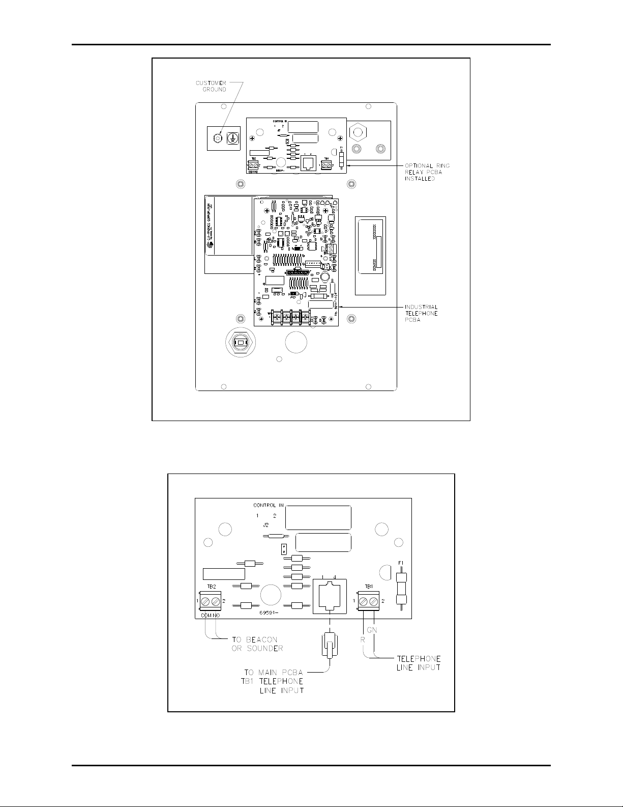
panel. See Figure 1.
4. Align the Ring Relay PCBA with the two standoffs. Make note of the PCBA orientation in Figure 1.
5. Secure using two #6-32 screws provided.
6. Connect the incoming subscriber telephone line to TB1 on the Ring Relay PCBA as shown in
Figure 2.
7. Connect the external sounder or beacon to TB2 on the Ring Relay PCBA for activation with an
incoming telephone call. See Figure 2 and Figure 3.
8. Before reattaching the panel assembly, connect the USOC RJ11C modular connector cord (provided)
from the Industrial Telephone PCBA shown in Figure 4 to the Ring Relay PCBA shown in Figure 2.
f:\standard ioms - current release\42003 kit manuals \42003-274a. docx
01/15
Page 3
Pub. 42003-274A
ODEL 12565-009 AND 12565-010 RING DETECT KITS Page 3 of 7
M
Figure 1. Interior of the Front Panel
Figure 2. Ring Relay PCBA Wiring
f:\standard ioms - current release\42003 kit manuals \42003-274a. docx
01/15
Page 4

Pub. 42003-274A
ODEL 12565-009 AND 12565-010 RING DETECT KITS Page 4 of 7
M
Figure 3. Device Interconnection
Figure 4. TB1 Terminal Block on Industrial Telephone PCBA
Model 276-001 In stallation
Using the parts provided in the Model 12565-009 Ring Detect Relay Kit:
1. Remove six 10-32 security screws from front cover of telephone. Pull cover away from the back
box/enclosure. Retain the screws.
2. Disconnect the incoming subscriber telephone line; red (ring) and green (tip) from TB1 on the
Industrial Phone PCBA.
3. Install the two 6-32 1.25-inches F/F standoffs (provided) onto the two weld studs on the back of the
panel. See Figure 5.
4. Align the Ring Relay PCBA with the two standoffs. (Note the PCBA orientation in Figure 1).
5. Secure using two #6-32 screws provided.
6. Connect the incoming subscriber telephone line to TB1 on the Ring Relay PCBA as shown on
Figure 2.
7. Connect the external sounder or beacon to TB2 on the Ring Relay PCBA for activation with an
incoming telephone call. See Figure 2 and Figure 3.
8. Before reattaching the panel assembly, connect the USOC RJ11C modular connector cord (provided)
from the Industrial Phone PCBA shown in Figure 4 to the Ring Relay PCBA shown in Figure 2.
f:\standard ioms - current release\42003 kit manuals \42003-274a. docx
01/15
Page 5

Pub. 42003-274A
ODEL 12565-009 AND 12565-010 RING DETECT KITS Page 5 of 7
M
Figure 5.
f:\standard ioms - current release\42003 kit manuals \42003-274a. docx
01/15
Page 6

Pub. 42003-274A
ODEL 12565-009 AND 12565-010 RING DETECT KITS Page 6 of 7
M
Model 246-001 an d 256-001 Installatio n
Using the parts provided in the Model 12565-010 Ring Detect Relay Kit:
1. Remove four 10-32 screws from front cover of telephone. Pull cover away from the back
box/enclosure. Retain the screws.
2. Disconnect the incoming subscriber telephone line; red (ring) and green (tip) from TB1 on the
Industrial Phone PCBA.
3. Remove two #4-40 screws installed above ringer. See Figure 6. Replace with two #4-40 1.18-
inches M/F standoffs (provided).
4. Install two #4-40 1.25-inches M/F sta ndof fs (pr ov ided) into front cover inserts located below
ringer.
5. Align Ringer Relay PCBA mounting plate (provided) to four standoffs. Note orientation of plate.
6. Secure with four #4-40 screws (provided).
7. Align the Ring Relay PCBA with the two standoffs (part of the Ringer Relay Mounting Plate). (Note
the PCBA orientation in Figure 7).
8. Secure using two #4-40 screws provided.
9. Connect the incoming subscriber telephone line to TB1 on the Ring Relay PCBA as shown on
Figure 2.
10. Connect the external sounder or beacon to TB2 on the Ring Relay PCBA for activation with and
incoming telephone call. See Figure 2 and Figure 3.
11. Before reattaching the panel assembly, connect the USOC RJ11C modular connector cord (provided)
from the Industrial Phone PCBA shown in Figure 4 to the Ring Relay PCBA shown in Figure 2.
f:\standard ioms - current release\42003 kit manuals \42003-274a. docx
01/15
Page 7

Pub. 42003-274A
ODEL 12565-009 AND 12565-010 RING DETECT KITS Page 7 of 7
M
Figure 6.
f:\standard ioms - current release\42003 kit manuals \42003-274a. docx
01/15
Figure 7.
Page 8

Warranty
Equipment. GAI-Tronics warrants for a period of one (1) year from the date of shipment, that any
GAI-Tronics equipment supplied hereunder shall be free of defects in material and workmanship, shall
comply with the then-current product specifications and product literature, and if applicable, shall be fit
for the purpose specified in the agreed-upon quotation or proposal document. If (a) Seller’s goods prove
to be defective in workmanship and/or material under normal and proper usage, or unfit for the purpose
specified and agreed upon, and (b) Buyer’s claim is made within the warranty period set forth above,
Buyer may return such goods to GAI-Tronics’ nearest depot repair facility, freight prepaid, at which time
they will be repaired or replaced, at Seller’s option, without charge to Buyer. Repair or replacement shall
be Buyer’s sole and exclusive remedy. The warranty period on any repaired or replacement equipment
shall be the greater of the ninety (90) day repair warranty or one (1) year from the date the original
equipment was shipped. In no event shall GAI-Tronics warranty obligations with respect to equipment
exceed 100% of the total cost of the equipment supplied hereunder. Buyer may also be entitled to the
manufacturer’s warranty on any third-party goods supplied by GAI-Tronics hereunder. The applicability
of any such third-party warranty will be determined by GAI-Tronics.
Services. Any services GAI-Tronics provides hereunder, whether directly or through subcontractors,
shall be performed in accordance with the standard of care with which such services are normally
provided in the industry. If the services fail to meet the applicable industry standard, GAI-Tronics will
re-perform such services at no cost to buyer to correct said deficiency to Company's satisfaction provided
any and all issues are identified prior to the demobilization of the Contractor’s personnel from the work
site. Re-performance of services shall be Buyer’s sole and exclusive remedy, and in no event shall GAITronics warranty obligations with respect to services exceed 100% of the total cost of the services
provided hereunder.
Warranty Periods. Every claim by Buyer alleging a defect in the goods and/or services provided
hereunder shall be deemed waived unless such claim is made in writing within the applicable warranty
periods as set forth above. Provided, however, that if the defect complained of is latent and not
discoverable within the above warranty periods, every claim arising on account of such latent defect shall
be deemed waived unless it is made in writing within a reasonable time after such latent defect is or
should have been discovered by Buyer.
Limitations / Exclusions. The warranties herein shall not apply to, and GAI-Tronics shall not be
responsible for, any damage to the goods or failure of the services supplied hereunder, to the extent
caused by Buyer’s neglect, failure to follow operational and maintenance procedures provided with the
equipment, or the use of technicians not specifically authorized by GAI-Tronics to maintain or service the
equipment. THE WARRANTIES AND REMEDIES CONTAINED HEREIN ARE IN LIEU OF AND
EXCLUDE ALL OTHER WARRANTIES AND REMEDIES, WHETHER EXPRESS OR IMPLIED BY
OPERATION OF LAW OR OTHERWISE, INCLUDING ANY WARRANTIES OF
MERCHANTABILITY OR FITNESS FOR A PARTICULAR PURPOSE.
Return Policy
If the equipment requires service, contact your Regional Service Center for a return authorization number
(RA#). Equipment should be shipped prepaid to GAI-Tronics with a return authorization number and a
purchase order number. If the equipment is under warranty, repairs or a replacement will be made in
accordance with the warranty policy set forth above. Please include a written explanation of all defects to
assist our technicians in their troubleshooting efforts.
Call 800-492-1212 (inside the USA) or 610-777-1374 (outside the USA) for help identifying the
Regional Service Center closest to you.
(Rev. 10/06)
 Loading...