

Page 1
Pub. 42003-248C
GAI-TRONICS® CORPORATION
A HUBBELL COMPANY
SMART Handset Telephone PCBA
Replacement Kit
Model 12562-110
Confidential ity Notice
This manual is provided solely as an operational, installation, and maintenance guide and contains sensitive
business and technical information that is confidential and proprietary to GAI-Tronics. GAI-Tronics
retains all intellectual property and other rights in or to the information contained herein, and such
information may only be used in connection with the operation of your GAI-Tronics product or system.
This manual may not be disclosed in any form, in whole or in part, directly or indirectly, to any third party.
General Information
The Model 12562-110 SMART Handset Telephone PCBA Replacement Kit contains a printed circuit
board assembly (PCBA) to be used in the following GAI-Tronics SMART Handset telephones:
226-005 246-005 256-005 276-005
227-005 247-005 257-005 277-005
The PCBA included in this kit can also be used as a replacement in the following GAI-Tronics telephone
models:
246-003 256-003 276-003
247-003 257-003 277-003
Important Note about TMA
ATTENTION
The PCBA included in this kit r equires the use of TMA version 7.4.1 or newer.
Failure to upgrade an operating TMA system to version 7.4.1 will result in the newly upgraded
telephone having a Configuration Synchronization error. Upgrading to TMA 7.4.1 eliminates this
issue and will not affect the operation of existing SMART Telephones (2xx-003 Series).
To upgrade an existing TMA system, please follow these instructions:
Using the TMA computer, go to www.gai-tronics.com.
Locate the TMA Upgrade button at the upper left side of the home page and click. This will take you
to the upgrade page. Follow the instructions noted on this page.
GAI-Tronics Corporation 400 E. Wyomissing Ave. Mohnton, PA 19540 USA
610-777-1374 800-492-1212 Fax: 610-796-5954
V
ISIT WWW.GAI-TRONICS.COM FOR PRODUCT LITERATURE AND MANUALS
Page 2

Pub. 42003-248C
ODEL 12562-110 SMART HANDSET TELEPHONE PCBA REPLACEMENT KIT Page 2 of 10
M
Installation
Electrostatic Discharge (ESD) Protection
Your telephone may have an earth ground terminal provision. If so, ensure that it is connected to ground
in accordance with all local safety regulations and the National Electrical Code (NEC). Grounding has to
be ensured for safe and stable communications. Do not use long and coiled ground wires. Trim ground
wires to the required length. Use a star configuration whenever possible.
Models 246-003, 247-003, 256-003 & 257-003
Removing the Old PCBA
1. Use a Phillips screwdriver to remove the four front panel screws and remove the panel from the
enclosure after disconnecting the telephone line.
2. Disconnect the handset, hookswitch, push button, keypad (Models 246-003 and 256-003 only), and
ringer cable(s) from the PCBA. Record the location of each connect ion for later reconne ct ion.
3. Disconnect the red and green wires from the telephone line connection on the PCBA. Save the
modular cord.
4. Depress the locking tab on each nylon standoff while lifting up on that corner of the PCBA to remove
it.
5. Clip the tie wrap securing the wires together.
Installing the New PCBA
1. Align the holes of the new PCBA with the snap-on nylon standoffs in the telephone, maintaining
proper orientation. See Figure 3 as an example.
2. Press firmly on each corner of the PCBA to lock in the standoffs.
3. Reconnect the red (ring) and green (tip) telephone wires to the PCBA.
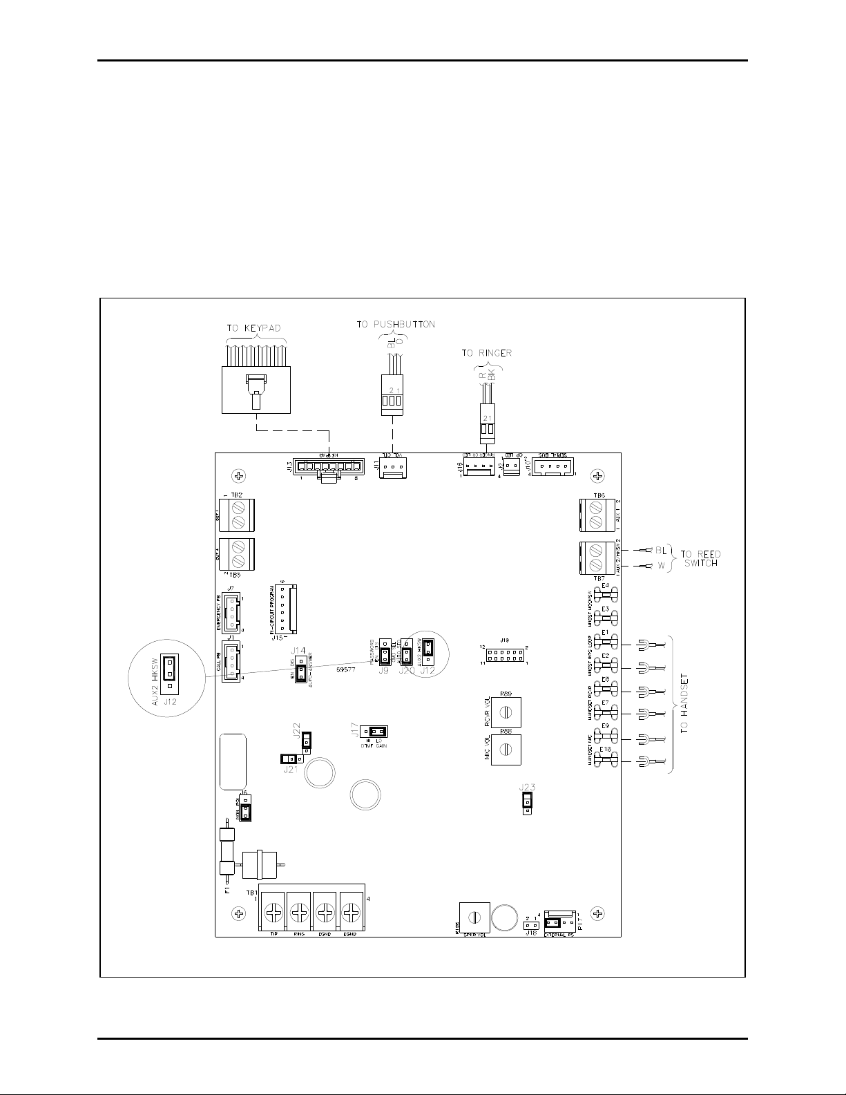
4. Refer to Figure 1 for locations of the connectors on the new PCBA. (N
OTE: Keypad connector is
used in Models 246-003 and 256-003 only.)
5. Secure wires using tie wrap included.
6. Move jumper J12 from its current position to that shown in Figure 1.
7. Please refer to Pub. 42004-439, available at www.gai-tronics.com
, for further information regarding
board jumpers.
f:\standard ioms - current release\42003 kit manuals \42003-248c.doc
02/13
Page 3
Pub. 42003-248C
ODEL 12562-110 SMART HANDSET TELEPHONE PCBA REPLACEMENT KIT Page 3 of 10
M
Synchronize with TMA
After installing this replacement PCBA in any -003 telephone, use TMA to synchronize the TMA phone
record to the telephone:
1. Right click on the TMA phone icon, select Quick Poll, choose the option None, and click OK.
2. Right click on the TMA phone icon, select Quick Poll, choose the option Send All, and click OK.
After poll call of step 1 completes, the phone’s icon will change from being a Type B handset type
showing a gray surface-mount 246-style (black background) to a view of a Type A type silver flushmount faceplate with a black handset.
f:\standard ioms - current release\42003 kit manuals \42003-248c.doc
02/13
Figure 1.
Page 4

Pub. 42003-248C
ODEL 12562-110 SMART HANDSET TELEPHONE PCBA REPLACEMENT KIT Page 4 of 10
M
Models 276-003 and 277-003
Removing the Old PCBA
1. Use the Model 233-001 Security Screwdriver to remove the six front panel screws and remove the
panel from its back box after disconnecting the telephone line.
2. Disconnect the handset, hookswitch, push button, keypad (Model 276-003 only), and ringer cable(s)
from the PCBA. Record the location of each connection for later reconnection.
3. Disconnect the red and green wires from the telephone line connection on the PCBA. Save the
modular cord.
4. Depress the locking tab on each nylon standoff while lifting up on that corner of the PCBA to remove
it.
5. Clip the tie wrap securing the wires together.
Installing the New PCBA
1. Align the holes of the new PCBA with the snap-on nylon standoffs in the telephone, maintaining
proper orientation. See Figure 4 as an example.
2. Press firmly on each corner of the PCBA to lock in the standoffs.
3. Reconnect the red (ring) and green (tip) telephone wires to the PCBA.
4. Install the ring lug of the (longer) ground cable provided to the ground stud on the front panel, and the
spade lug to the terminal block (TB1)
5. Refer to Figure 1 for locations of the connectors on the new PCBA. (N
EGND.
OTE: Keypad connector used
in Model 276-003 only.)
6. Secure wires using tie wrap included.
7. Move jumper J12 from its current position to that shown in Figure 1.
8. Please refer to Pub. 42004-439, available at www.gai-tronics.com
, for further information regarding
board jumpers.
Synchronize with TMA
After installing this replacement PCBA in any -003 telephone, use TMA to synchronize the TMA phone
record to the telephone:
1. Right click on the TMA phone icon, select Quick Poll, choose the option None, and click OK.
2. Right click on the TMA phone icon, select Quick Poll, choose the option Send All, and click OK.
After poll call of step 1 completes, the phone’s icon will change from being a Type B handset type
showing a gray surface-mount 246-style (black background) to a view of a Type A type silver flushmount faceplate with a black handset.
f:\standard ioms - current release\42003 kit manuals \42003-248c.doc
02/13
Page 5

Pub. 42003-248C
ODEL 12562-110 SMART HANDSET TELEPHONE PCBA REPLACEMENT KIT Page 5 of 10
M
Models 226-005 and 227-005
Removing the Old PCBA
1. Use the Model 233-001 Security Screwdriver to remove the eight front panel screws and remove the
panel from the enclosure after disconnecting the telephone line.
2. Disconnect the handset, hookswitch, push button, keypad (Model 226-005 only), and ringer cable(s)
from the PCBA. Record the location of each connection for later reconnection.
3. Disconnect the red and green wires and ground wire (if present) from the telephone line connection
on the PCBA. Save the modular cord.
4. Depress the locking tab on each nylon standoff while lifting up on that corner of the PCBA to remove
it.
Installing the New PCBA
1. Align the holes of the new PCBA with the snap-on nylon standoffs in the telephone, maintaining
proper orientation. Refer to Figure 2 as an example.
2. Press firmly on each corner of the PCBA to lock in the standoffs.
3. Reconnect the red (ring) and green (tip) telephone wires to the PCBA.
4. Reconnect the handset, hookswitch, push button, keypad (Model 226-005 only), and ringer cable(s) to
the PCBA.
5. If not previously installed, attach the ring lug of the (shorter) ground cable provided to the ground
stud on the front panel; and the spade lug to terminal block TB1. See Figure 2.
If the ground wire was present, reconnect it to TB1.
6. Use the Model 233-001 Security Screwdriver to install the eight front panel screws.
7. Press firmly on each corner of the PCBA to lock in the standoffs.
8. Reconnect the red (ring) and green (tip) telephone wires to the PCBA.
9. Reconnect the handset, hookswitch, push button, keypad (Model 226-005 only), and ringer cable(s) to
the PCBA.
10. Use the Model 233-001 Security Screwdriver to install the eight front panel screws.
f:\standard ioms - current release\42003 kit manuals \42003-248c.doc
02/13
Page 6

Pub. 42003-248C
ODEL 12562-110 SMART HANDSET TELEPHONE PCBA REPLACEMENT KIT Page 6 of 10
M
Figure 2. PCBA Connections for Models 226-005 and 227-005
f:\standard ioms - current release\42003 kit manuals \42003-248c.doc
02/13
Page 7

Pub. 42003-248C
ODEL 12562-110 SMART HANDSET TELEPHONE PCBA REPLACEMENT KIT Page 7 of 10
M
Models 246-005, 247-005, 256-005, and 257-005
Removing the Old PCBA
1. Use a Phillips screwdriver to remove the four front panel screws and remove the panel from the
enclosure after disconnecting the telephone line.
2. Disconnect the handset, hookswitch, push button, keypad (Models 246-005 and 256-005 only), and
ringer cable(s) from the PCBA. Record the location of each connect ion for later reconne ct ion.
3. Disconnect the red and green wires from the telephone line connection on the PCBA. Save the
modular cord.
4. Depress the locking tab on each nylon standoff while lifting up on that corner of the PCBA to remove
it.
Installing the New PCBA
1. Align the holes of the new PCBA with the snap-on nylon standoffs in the telephone, maintaining
proper orientation. See Figure 3.
2. Press firmly on each corner of the PCBA to lock in the standoffs.
3. Reconnect the red (ring) and green (tip) telephone wires to the PCBA.
4. Reconnect the handset, hookswitch, push button, keypad (Models 246-005 and 256-005 only), and
ringer cable(s) to the PCBA.
5. Use a Phillips screwdriver to install the four front panel screws.
f:\standard ioms - current release\42003 kit manuals \42003-248c.doc
02/13
Page 8

Pub. 42003-248C
ODEL 12562-110 SMART HANDSET TELEPHONE PCBA REPLACEMENT KIT Page 8 of 10
M
Figure 3. PCBA Connections for Models 246-005, 247-005, 256-005, and 257-005
f:\standard ioms - current release\42003 kit manuals \42003-248c.doc
02/13
Page 9

Pub. 42003-248C
ODEL 12562-110 SMART HANDSET TELEPHONE PCBA REPLACEMENT KIT Page 9 of 10
M
Models 276-005 and 277-005
Removing the Old PCBA
1. Use the Model 233-001 Security Screwdriver to remove the six front panel screws and remove the
panel from its back box after disconnecting the telephone line.
2. Disconnect the handset, hookswitch, push button, keypad (Model 276-005 only), and ringer cable(s)
from the PCBA. Record the location of each connection for later reconnection.
3. Disconnect the red and green wires and ground wire (if present) from the telephone line connection
on the PCBA. Save the modular cord.
4. Depress the locking tab on each nylon standoff while lifting up on that corner of the PCBA to remove
it.
Installing the New PCBA
1. Align the holes of the new PCBA with the snap-on nylon standoffs in the telephone, maintaining
proper orientation. See Figure 4.
2. Press firmly on each corner of the PCBA to lock in the standoffs.
3. Reconnect the red (ring) and green (tip) telephone wires to the PCBA.
4. If not previously installed, attach the ring lug of the (longer) ground cable provided to the ground stud
on the front panel and the spade lug to terminal block TB1. See Figure 4.
If the ground wire was present, reconnect to TB1.
5. Reconnect the handset, hookswitch, push button, keypad (Model 276-005 only), and ringer cable(s) to
the PCBA.
6. Use the Model 233-001 Security Screwdriver to install the six front panel screws.
f:\standard ioms - current release\42003 kit manuals \42003-248c.doc
02/13
Page 10

Pub. 42003-248C
ODEL 12562-110 SMART HANDSET TELEPHONE PCBA REPLACEMENT KIT Page 10 of 10
M
Figure 4. PCBA Connections for Models 276-005 and 277-005
f:\standard ioms - current release\42003 kit manuals \42003-248c.doc
02/13
Page 11

Warranty
Equipment. GAI-Tronics warrants for a period of one (1) year from the date of shipment, that any
GAI-Tronics equipment supplied hereunder shall be free of defects in material and workmanship, shall
comply with the then-current product specifications and product literature, and if applicable, shall be fit
for the purpose specified in the agreed upon quotation or proposal document. If (a) Seller’s goods prove
to be defective in workmanship and/or material under normal and proper usage, or unfit for the purpose
specified and agreed upon, and (b) Buyer’s claim is made within the warranty period set forth above,
Buyer may return such goods to GAI-Tronics nearest depot repair facility, freight prepaid, at which time
they will be repaired or replaced, at Seller’s option, without charge to Buyer. Repair or replacement shall
be Buyer’s sole and exclusive remedy. The warranty period on any repaired or replacement equipment
shall be the greater of the ninety (90) day repair warranty or one (1) year from the date the original
equipment was shipped. In no event shall GAI-Tronics warranty obligations with respect to equipment
exceed 100% of the total cost of the equipment supplied hereunder. Buyer may also be entitled to the
manufacturer’s warranty on any third-party goods supplied by GAI-Tronics hereunder. The applicability
of any such third-party warranty will be determined by GAI-Tronics.
Services. Any services GAI-Tronics provides hereunder, whether directly or through subcontractors,
shall be performed in accordance with the standard of care with which such services are normally
provided in the industry. If the services fail to meet the applicable industry standard, GAI-Tronics will reperform such services at no cost to buyer to correct said deficiency to Company's satisfaction provided
any and all issues are identified prior to the demobilization of the Contractor's personnel from the work
site. Re-performance of services shall be Buyer's sole and exclusive remedy, and in no event shall GAITronics warranty obligations with respect to services exceed 100% of the total cost of the services
provided hereunder.
Warranty Periods. Every claim by Buyer alleging a defect in the goods and/or services provided
hereunder shall be deemed waived unless such claim is made in writing within the applicable warranty
periods as set forth above. Provided, however, that if the defect complained of is latent and not
discoverable within the above warranty periods, every claim arising on account of such latent defect shall
be deemed waived unless it is made in writing within a reasonable time after such latent defect is or
should have been discovered by Buyer.
Limitations / Exclusions. The warranties herein shall not apply to, and GAI-Tronics shall not be
responsible for, any damage to the goods or failure of the services supplied hereunder, to the extent
caused by Buyer’s neglect, failure to follow operational and maintenance procedures provided with the
equipment, or the use of technicians not specifically authorized by GAI-Tronics to maintain or service the
equipment. THE WARRANTIES AND REMEDIES CONTAINED HEREIN ARE IN LIEU OF AND
EXCLUDE ALL OTHER WARRANTIES AND REMEDIES, WHETHER EXPRESS OR IMPLIED BY
OPERATION OF LAW OR OTHERWISE, INCLUDING ANY WARRANTIES OF
MERCHANTABILITY OR FITNESS FOR A PARTICULAR PURPOSE.
Return Policy
If the equipment requires service, contact your Regional Service Center for a return authorization number
(RA#). Equipment should be shipped prepaid to GAI-Tronics with a return authorization number and a
purchase order number. If the equipment is under warranty, repairs or a replacement will be made in
accordance with the warranty policy set forth above. Please include a written explanation of all defects to
assist our technicians in their troubleshooting efforts.
Call 800-492-1212 (inside the USA) or 610-777-1374 (outside the USA) for help identifying the
Regional Service Center closest to you.
(Rev. 10/06)
 Loading...