

Page 1

Pub. 42003-185A
GAI-TRONICS® CORPORATION
A HUBBELL COMPANY
AC Transformer Shield Kit
Model 12560-101
Confidentiality Notice
This manua l is provide d sole ly as an operatio nal, installation, and ma inte nance guide and conta ins
sensitive business and t e chnic al infor ma tion w hich is conf ident ial and pr op riet ary to GAI-Tro nics.
GAI-Tronics retains all intellectual property and other rights in or to the information contained herein,
and such information may only be used in connection with the operation of your GAI-Tronics product or
system. This manu al may not be dis clos e d in any form, in whole or in pa rt, direct ly or i ndir ectly, to a ny
third pa r ty.
General Information
The Model 12560-101 AC Transformer Shield Kit is installed with the speaker amp/power supply PCBA
when used in SmartSeries Models 701-902 and 701-904. This kit includes the following components:
Qty Description
2
4-40 × 1-5/8 inches long Phillips head machine screw
2
Nylon self-retaining spacer #4 × 3/8 inches long
1 Steel shield
1 Instruction sheet
Recommende d Tools
• #1 Phillips screwdriver
• #2 Phillips screwdriver
Installation
Installation of the shield is as follows:
WARNING
1. Disconnect ac power to the unit.
Disconnect ac po wer from the unit before o pening o r s erv icing unit.
2. Loosen the four front panel screws holding unit into enclosure and retain.
GAI-Tronics Corporation P.O. Box 1060, Readi ng, PA 19607-1060 USA
610-777-1374 800-492-1212 Fax: 610-796-5954
ISIT WWW.GAI-TRONICS.COM FOR PRODUCT LITERATURE AND MANUALS
V
Page 2
Pub. 42003-185A
M
ODEL 12560-101 AC TRANSFORMER SHIELD KIT Page: 2 of 2
3. Loosen the four side screws holding the front panel to the rear chassis.
4. Carefully slide and separate the front panel from the rear chassis and lay the panel over to the right
side.
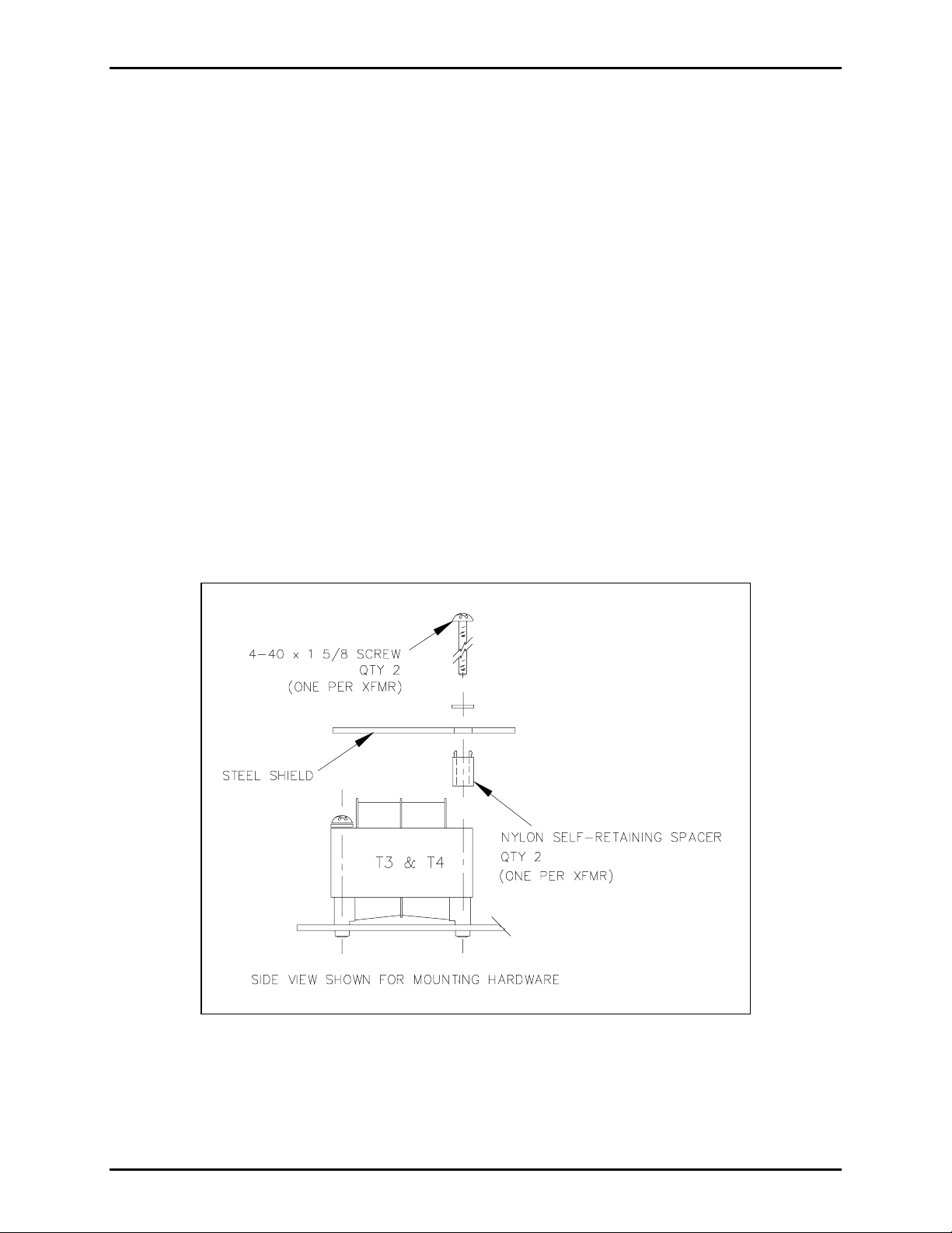
5. Remove the inner two 4-40 screws that secure the T3 and T4 transformers to the 69382-001 PCBA.
(One s c rew, located closest t o the ce nter of PCBA, is r e moved from each t ransf ormer .) R efer to
Figure 1 below.
N
OTE: Retain the two #4 internal tooth washers.
6. Insert the two spacers that are supplied into the same side of the shield.
7. Place the shield over top of T3 and T4 insuring that the spacers are against the core of the
transformers.
8. Using the retained lock washers and the longer, supplied screws, tighten the shield and T3 and T4
transformers to the PCBA.
9. Carefully mate the front panel to the rear chassis. Insure that all four side-mounted screws are
correctly located in the rear chassis and tighten.
10. Install the unit into enclosure, replace the four mounting screws, and tighten.
11. Apply ac pow er and check for prop er operation.
Figure 1.
\\s_eng\gtc proddoc s \st andard iom s - current release\42003 kit manuals \ 42003-185a.doc
6/00
Page 3

Warranty
Equipment. GAI-Tronics warrants for a period of one (1) year from the date of shipment, that any
GAI-Tronics equipment supplied hereunder shall be free of defects in material and workmanship, shall
comply with the then-current product specifications and product literature, and if applicable, shall be fit
for the purpose specified in the agreed-upon quotation or proposal document. If (a) Seller’s goods prove
to be defective in workmanship and/or material under normal and proper usage, or unfit for the purpose
specified and agreed upon, and (b) Buyer’s claim is made within the warranty period set forth above,
Buyer may return such goods to GAI-Tronics’ nearest depot repair facility, freight prepaid, at which time
they will be repaired or replaced, at Seller’s option, without charge to Buyer. Repair or replacement shall
be Buyer’s sole and exclusive remedy. The warranty period on any repaired or replacement equipment
shall be the greater of the ninety (90) day repair warranty or one (1) year from the date the original
equipment was shipped. In no event shall GAI-Tronics warranty obligations with respect to equipment
exceed 100% of the total cost of the equipment supplied hereunder. Buyer may also be entitled to the
manufacturer’s warranty on any third-party goods supplied by GAI-Tronics hereunder. The applicability
of any such third-party warranty will be determined by GAI-Tronics.
Services. Any services GAI-Tronics provides hereunder, whether directly or through subcontractors,
shall be performed in accordance with the standard of care with which such services are normally
provided in the industry. If the services fail to meet the applicable industry standard, GAI-Tronics will
re-perform such services at no cost to buyer to correct said deficiency to Company's satisfaction provided
any and all issues are identified prior to the demobilization of the Contractor’s personnel from the work
site. Re-performance of services shall be Buyer’s sole and exclusive remedy, and in no event shall GAITronics warranty obligations with respect to services exceed 100% of the total cost of the services
provided hereunder.
Warranty Periods. Every claim by Buyer alleging a defect in the goods and/or services provided
hereunder shall be deemed waived unless such claim is made in writing within the applicable warranty
periods as set forth above. Provided, however, that if the defect complained of is latent and not
discoverable within the above warranty periods, every claim arising on account of such latent defect shall
be deemed waived unless it is made in writing within a reasonable time after such latent defect is or
should have been discovered by Buyer.
Limitations / Exclusions. The warranties herein shall not apply to, and GAI-Tronics shall not be
responsible for, any damage to the goods or failure of the services supplied hereunder, to the extent
caused by Buyer’s neglect, failure to follow operational and maintenance procedures provided with the
equipment, or the use of technicians not specifically authorized by GAI-Tronics to maintain or service the
equipment. THE WARRANTIES AND REMEDIES CONTAINED HEREIN ARE IN LIEU OF AND
EXCLUDE ALL OTHER WARRANTIES AND REMEDIES, WHETHER EXPRESS OR IMPLIED BY
OPERATION OF LAW OR OTHERWISE, INCLUDING ANY WARRANTIES OF
MERCHANTABILITY OR FITNESS FOR A PARTICULAR PURPOSE.
Return Policy
If the equipment requires service, contact your Regional Service Center for a return authorization number
(RA#). Equipment should be shipped prepaid to GAI-Tronics with a return authorization number and a
purchase order number. If the equipment is under warranty, repairs or a replacement will be made in
accordance with the warranty policy set forth above. Please include a written explanation of all defects to
assist our technicians in their troubleshooting efforts.
Call 800-492-1212 (inside the USA) or 610-777-1374 (outside the USA) for help identifying the
Regional Service Center closest to you.
(Rev. 10/06)
 Loading...