

Page 1

Pub. 42003-159
GAI-TRONICS® CORPORATION
A HUBBELL COMPANY
FSK Mode m Repl acement PCBA
Model 12555-001
Confidentiality Notice
This manua l is provide d sole ly as an operatio nal, installation, and ma inte nance guide and conta ins
sensitive business and t e chnical informatio n tha t is confidentia l and pr opri et ary to GAI- Tronics.
GAI-Tronics retains all intellectual property and other rights in or to the information contained herein,
and such information may only be used in connection with the operation of your GAI-Tronics product or
system. This manu al may not be dis clos e d in any form, in whole or in pa rt, direct ly or i ndir ectly, to a ny
third pa r ty.
General Information
The 1255-001 FSK Modem Kit contains one 69277-102 PCBA for use in GAI-Tronics SmartHandset™
Sta tions and S ma rtAmplifier™ Stations.
Instructions
WARNING
Removal of Old PCBA
NOTE: When disassembling unit be sure to save all hardware, as it will be needed with unit is
reassembled.
1. Loosen four screws at corners of front panel and pull plug-in amp from enclosure. All maintenance
work f rom this p oint s hould be performed a t a work bench with the operator prop erly grounded t o
avoid static dis charge.
2. Loosen four chassis screws (Phillips) on the top and bottom of the unit.
3. Carefully slide the chassis to the left and separate from the front panel. CAUTION – the Power
Supply harness inside is short; do not pull apart abruptly.
4. Remove power supply wire harness from J6 of 69241 PCBA by depressing tab on locking connector.
5. Remove aux/subset connector at J2 from 69228 PCBA (for 701-804 only).
6. Disconnect spade terminals at E1, E2,…E7. Needle nose pliers may be required.
Remove power to station prior to servicing.
GAI-Tronics Corporation P.O. Box 1060, Readi ng, PA 19607-1060 USA
610-777-1374 800-492-1212 Fax: 610-796-5954
ISIT WWW.GAI-TRONICS.COM FOR PRODUCT LITERATURE AND MANUALS
V
Page 2
Pub. 42003-159
12555-001
REPLACEMENT PCBA KIT Page: 2 of 2
7. Remove four screws that secure the 69228 PCBA. Disconnect the assembly by grabbing the PCBA
at the sides near the J1 connector. Unplug from the PCBA below and set aside.
8. Remove the four ¼-inch hex standoffs from the corners of the 69227 PCBA.
9. Unplug the 69227 PCBA from the baseboard by grabbing at the sides near the J1 connector.
Installatio n of New PC BA
1. Plug new 69227 into 69241 baseboard at J1 connector.
2. Secure 69227 PCBA with existing standoffs.
3. Plug 69228 handset PCBA back into J1 of the 69227 PCBA and secure with existing screws.
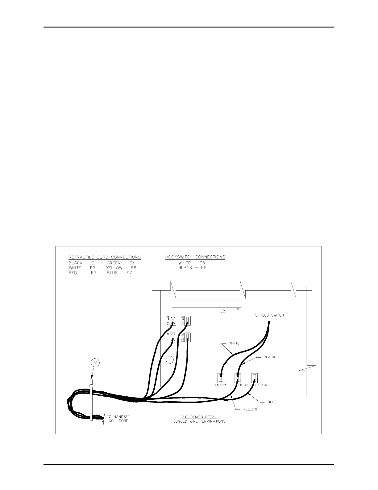
4. Reconnect spade lugs. See Figure 1.
5. Reattach aux/subset connector at J2 of 69228 PCBA.
6. Reconnect 12 conductor wire harness from 69241 baseboard to 69242 Power Supply on front panel at
J1.
7. Reattach chassis and front panel, secure top and bottom chassis screws.
8. Plug amp into enclosure and tighten four front panel screws.
9. Re-apply power to the station.
Figure 1.
\\s_eng\gtc proddoc s \st andard iom s - current release\42003 kit manuals \ 42003-159. doc
9/96
Page 3

Warranty
Equipment. GAI-Tronics warrants for a period of one (1) year from the date of shipment, that any
GAI-Tronics equipment supplied hereunder shall be free of defects in material and workmanship, shall
comply with the then-current product specifications and product literature, and if applicable, shall be fit
for the purpose specified in the agreed-upon quotation or proposal document. If (a) Seller’s goods prove
to be defective in workmanship and/or material under normal and proper usage, or unfit for the purpose
specified and agreed upon, and (b) Buyer’s claim is made within the warranty period set forth above,
Buyer may return such goods to GAI-Tronics’ nearest depot repair facility, freight prepaid, at which time
they will be repaired or replaced, at Seller’s option, without charge to Buyer. Repair or replacement shall
be Buyer’s sole and exclusive remedy. The warranty period on any repaired or replacement equipment
shall be the greater of the ninety (90) day repair warranty or one (1) year from the date the original
equipment was shipped. In no event shall GAI-Tronics warranty obligations with respect to equipment
exceed 100% of the total cost of the equipment supplied hereunder. Buyer may also be entitled to the
manufacturer’s warranty on any third-party goods supplied by GAI-Tronics hereunder. The applicability
of any such third-party warranty will be determined by GAI-Tronics.
Services. Any services GAI-Tronics provides hereunder, whether directly or through subcontractors,
shall be performed in accordance with the standard of care with which such services are normally
provided in the industry. If the services fail to meet the applicable industry standard, GAI-Tronics will
re-perform such services at no cost to buyer to correct said deficiency to Company's satisfaction provided
any and all issues are identified prior to the demobilization of the Contractor’s personnel from the work
site. Re-performance of services shall be Buyer’s sole and exclusive remedy, and in no event shall GAITronics warranty obligations with respect to services exceed 100% of the total cost of the services
provided hereunder.
Warranty Periods. Every claim by Buyer alleging a defect in the goods and/or services provided
hereunder shall be deemed waived unless such claim is made in writing within the applicable warranty
periods as set forth above. Provided, however, that if the defect complained of is latent and not
discoverable within the above warranty periods, every claim arising on account of such latent defect shall
be deemed waived unless it is made in writing within a reasonable time after such latent defect is or
should have been discovered by Buyer.
Limitations / Exclusions. The warranties herein shall not apply to, and GAI-Tronics shall not be
responsible for, any damage to the goods or failure of the services supplied hereunder, to the extent
caused by Buyer’s neglect, failure to follow operational and maintenance procedures provided with the
equipment, or the use of technicians not specifically authorized by GAI-Tronics to maintain or service the
equipment. THE WARRANTIES AND REMEDIES CONTAINED HEREIN ARE IN LIEU OF AND
EXCLUDE ALL OTHER WARRANTIES AND REMEDIES, WHETHER EXPRESS OR IMPLIED BY
OPERATION OF LAW OR OTHERWISE, INCLUDING ANY WARRANTIES OF
MERCHANTABILITY OR FITNESS FOR A PARTICULAR PURPOSE.
Return Policy
If the equipment requires service, contact your Regional Service Center for a return authorization number
(RA#). Equipment should be shipped prepaid to GAI-Tronics with a return authorization number and a
purchase order number. If the equipment is under warranty, repairs or a replacement will be made in
accordance with the warranty policy set forth above. Please include a written explanation of all defects to
assist our technicians in their troubleshooting efforts.
Call 800-492-1212 (inside the USA) or 610-777-1374 (outside the USA) for help identifying the
Regional Service Center closest to you.
(Rev. 10/06)
 Loading...