

Page 1

Pub. 42003-122A
GAI-TRONICS® CORPORATION
A HUBBELL COMPANY
Rotar y Switch Harness Assembly
Replacement Kit
MODEL 61504-053
Confidentiality Notice
This manual is provided solely as an operational, installation, and maintenance guide and contains
sensitive business and technical information which is confidential and proprietary to GAI-Tronics. GAITronics retains all intellectual property and other rights in or to the information contained herein, and such
information may only be used in connection with the operation of your GAI-Tronics product or system.
This manual may not be disclosed in any form, in whole or in part, directly or indirectly, to any third party.
General Information
The Model 61504-053 Rotary Switch Harness Assembly Replacement Kit is intended for use on the
Model 478-002 Centra-Page II/Electro-Sound II (CPII/ESII) Desktop Subset.
Installation
Removing the Old Harness Assembly
1. Locate the party-line selector switch on the front panel of the subset. Use flat blade screwdriver to
pop out the cap in the center of the knob.
2. Using long-nosed pliers or a wrench, loosen, but do not remove, the hex nut inside the party-line
selector knob.
3. Remove the party-line selector knob.
4. Use the long-nose pliers or a wrench to remove and discard the collar nut securing the party-line
selector switch to the front panel.
5. Remove and save the four screws securing the housing to the bottom panel.
6. Hinge the housing forward to access the interior of the telephone. Locate the post header on the
printed circuit board marked
header.
J3, PARTY LINE SELECT. Disengage the connector from this post
7. Pull the party-line selector switch through the rear of the front panel, and discard the old harness
assembly.
8. Remove and discard the two-party line label.
GAI-Tronics Corporation 400 E. Wyomissing Ave. Mohnton, PA 19540 USA
610-777-1374 800-492-1212 Fax: 610-796-5954
ISIT WWW.GAI-TRONICS.COM FOR PRODUCT LITERATURE AND MANUALS
V
Page 2
Pub. 42003-122A
M
ODEL 61504-053 ROTARY SWITCH HARNESS REPLACEMENT KIT Page: 2 of 2
Installing the New Harness Assembly
NOTE: Steps 1–3 may not be required depending on when the unit was manufactured.
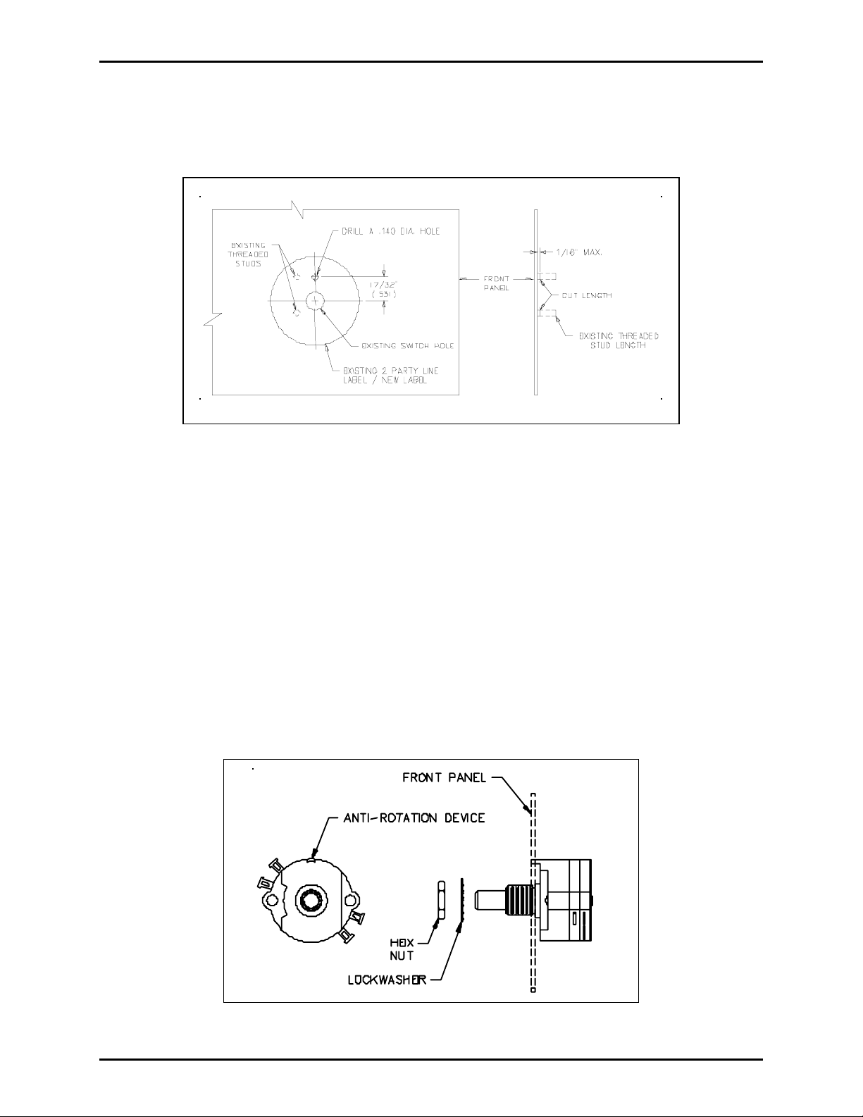
1. Drill a 0.140-inch (3.56 mm) hole in the front panel as shown in Figure 1.
Figure 1. Front Panel Modifications
2. Cut the threaded studs as shown in Figure 1.
3. Attach the two-party line label on the exterior of the front panel as shown in Figure 1.
4. Install the switch using the supplied hardware to the front panel as shown in Figure 2. The
anti-rotation device MUST go into the 0.140-inch (3.56 mm) drilled hole.
5. Reconnect the connector to the post header marked
J3, PARTY LINE SELECT.
6. Place the party-line selector knob over the top of the switch assembly.
7. Use a pair of pliers to tighten the hex nut, and to secure the party-line selector knob.
8. Snap the cap into the party-line selector knob.
9. Close the subset using the four screws from Step 5 in the previous section.
Figure2. Switch Assembly
f:\standard ioms - current release\42003 kit manuals\42003-122a.doc
01/12
Page 3

Warranty
Equipment. GAI-Tronics warrants for a period of one (1) year from the date of shipment, that any
GAI-Tronics equipment supplied hereunder shall be free of defects in material and workmanship, shall
comply with the then-current product specifications and product literature, and if applicable, shall be fit
for the purpose specified in the agreed-upon quotation or proposal document. If (a) Seller’s goods prove
to be defective in workmanship and/or material under normal and proper usage, or unfit for the purpose
specified and agreed upon, and (b) Buyer’s claim is made within the warranty period set forth above,
Buyer may return such goods to GAI-Tronics’ nearest depot repair facility, freight prepaid, at which time
they will be repaired or replaced, at Seller’s option, without charge to Buyer. Repair or replacement shall
be Buyer’s sole and exclusive remedy. The warranty period on any repaired or replacement equipment
shall be the greater of the ninety (90) day repair warranty or one (1) year from the date the original
equipment was shipped. In no event shall GAI-Tronics warranty obligations with respect to equipment
exceed 100% of the total cost of the equipment supplied hereunder. Buyer may also be entitled to the
manufacturer’s warranty on any third-party goods supplied by GAI-Tronics hereunder. The applicability
of any such third-party warranty will be determined by GAI-Tronics.
Services. Any services GAI-Tronics provides hereunder, whether directly or through subcontractors,
shall be performed in accordance with the standard of care with which such services are normally
provided in the industry. If the services fail to meet the applicable industry standard, GAI-Tronics will
re-perform such services at no cost to buyer to correct said deficiency to Company's satisfaction provided
any and all issues are identified prior to the demobilization of the Contractor’s personnel from the work
site. Re-performance of services shall be Buyer’s sole and exclusive remedy, and in no event shall GAITronics warranty obligations with respect to services exceed 100% of the total cost of the services
provided hereunder.
Warranty Periods. Every claim by Buyer alleging a defect in the goods and/or services provided
hereunder shall be deemed waived unless such claim is made in writing within the applicable warranty
periods as set forth above. Provided, however, that if the defect complained of is latent and not
discoverable within the above warranty periods, every claim arising on account of such latent defect shall
be deemed waived unless it is made in writing within a reasonable time after such latent defect is or
should have been discovered by Buyer.
Limitations / Exclusions. The warranties herein shall not apply to, and GAI-Tronics shall not be
responsible for, any damage to the goods or failure of the services supplied hereunder, to the extent
caused by Buyer’s neglect, failure to follow operational and maintenance procedures provided with the
equipment, or the use of technicians not specifically authorized by GAI-Tronics to maintain or service the
equipment. THE WARRANTIES AND REMEDIES CONTAINED HEREIN ARE IN LIEU OF AND
EXCLUDE ALL OTHER WARRANTIES AND REMEDIES, WHETHER EXPRESS OR IMPLIED BY
OPERATION OF LAW OR OTHERWISE, INCLUDING ANY WARRANTIES OF
MERCHANTABILITY OR FITNESS FOR A PARTICULAR PURPOSE.
Return Policy
If the equipment requires service, contact your Regional Service Center for a return authorization number
(RA#). Equipment should be shipped prepaid to GAI-Tronics with a return authorization number and a
purchase order number. If the equipment is under warranty, repairs or a replacement will be made in
accordance with the warranty policy set forth above. Please include a written explanation of all defects to
assist our technicians in their troubleshooting efforts.
Call 800-492-1212 (inside the USA) or 610-777-1374 (outside the USA) for help identifying the
Regional Service Center closest to you.
(Rev. 10/06)
 Loading...