

Page 1

Pub. 42003-149
GAI-TRONICS® CORPORATION
A HUBBELL COMPANY
Receiver/Amplifier Replacement Kit
MODEL 12550-102
Confidentiality Notice
This manual is pr ovided s olely as a n op erat ional, installation, and maintenance guide and contains sens itive
bus ines s and t echnic al infor ma tion which is conf idential and propriet ary to GAI-Tronics. GAI - Tronic s
retains a ll intellectual pr operty and other rights in or to t he inf ormation c ontained herein, and s uch
informa tion may only be used in connection wit h the operation of you r GAI- Tronic s pr oduct or system.
This ma nual may not be disclosed in any form, in whole or in p art, dir ec tly or indirectly, to any t hird pa rty.
General Information
This kit is used on the following model sta tions:
• 10450-003 • 10450-102 • 472-001 • 473-001 • 476-001 • 477-001 • 478-002
• 10450-101 • 10450-202 • 472-002 • 473-002 • 476-002 • 477-002
The Model 12550-102 kit includes the following components:
Description
Qty
1 Handset SMT PCBA
1 Headset receiver
2 Screw
2 Brass eyelet
Installation
Removing the Old Receiver
1. Unscrew the microphone cap , and remove the
microphone ass embly and nylon was her.
2. Loosen t he t wo screws on the micr ophone
assembly, and remove the three blac k wires a nd
brown wire. L oc ate the s plice connection of the
two white wir es . Remove the vinyl electrical tap e
fr o m the splice, a n d remove t h e l arger wh i te wire
(r eceiver wir e) fr o m the ju mper c lip. See Figure
1.
OTE: On older stations, the brown wire is
N
replaced by a green wir e.
Figure 1. J umper Clip Installation
GAI-Tronics Corporation P.O. Box 1060, Reading, PA 19607-1060 USA
610-777-1374 800-492-1212 Fax : 610-796-5954
ISIT WWW.GAI-TRONICS.COM FOR PRODUCT LITERATURE AND MANUALS
V
Page 2
Pub. 42003-149
M
ODEL 12550-102 RECEIVER AMPLIFIER REPLACEMENT KIT Page: 2 of 3
3. Remove the two sc rews that s ec ure the handset page swit ch to the handset. Ca refully remove the page
switch c over plate, actuat or cover, retur n spri ng, ac tua tor, and contact enclosure fr om t he handset
handle. See Figure 3.
4. Unscrew the receiver ca p , and c arefu lly remove the receiver/amplifier assembly.
5. Discard t he old receiver and amplifier assembly.
Installing the New Receiver and Amplifier PCBA
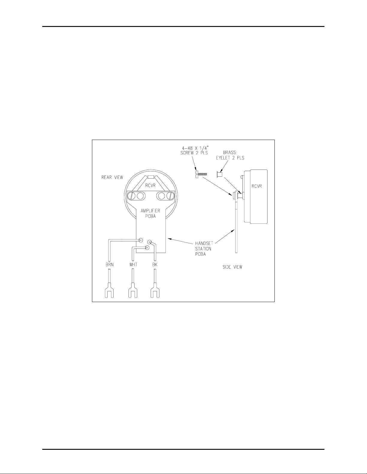
1. Place the new r eceiver element o n a fl at surface, and i n stall the a mplifier pri n ted circuit boa rd assembly
(PCBA) on the receiver using the brass eyelets and screws provided as shown in Fi gure 2.
Figure 2. Receiver/Amplifier I ns tallation Diagra m
2. Carefully ins ert t he wires fr om t he amplifier P CBA into t he handset handle (bla c k and br own wires go
to the microphone ca vity, and the white wir e goes to the page switch c utout midway on the handle).
3. Ins ert the a mplif i er P CBA in to t h e recei v er cavity of the handset handle u n til the r eceiver is pro per l y
seated i n the handset.
4. Rep l ace the receiver cap.
5. Insert the sp ade termina l f rom the receiver white wire into t he ju mper clip, along with the white wire
from the coil cord. See Figure 1. Tape the jumper clip with vinyl electrical tape.
\\s_eng\gtc proddoc s \ s tandard ioms - current release\ 42003 k it m anuals \42003-149.doc
8/95
Page 3

Pub. 42003-149
M
ODEL 12550-102 RECEIVER AMPLIFIER REPLACEMENT KIT Page: 3 of 3
6. Install the page switc h c ontact enclosure, actu ator, return spring, actu ator cover, and cover pla te using
the scr ews previously removed. See Figu re 3.
Figure 3. Pressbar Page Switch Detail Drawing
7. Connect the three black wir es from the r eceiver PC BA, pa ge s witch, and coil cor d to one termina l of
the microphone and the b rown wire f rom the receiver PC B A to the second terminal of the microphone.
See Figu re 4.
8. Carefully ins ert t he t ape sp lice into the micr op hone c avity, and push the wir es toward the pa ge s witch.
Install the coil cord st rain relief on the microp hone b rac ket as s hown in Figure 4. Insert the
microphone into the microphone cavit y on the handset.
9. Inst all the nylon wa sher on the microphone. See Figure 4.
10. R ep lace the microphone ca p.
Figure 4. Microphone Installation Dia gram
\\s_eng\gtc proddoc s \ s tandard ioms - current release\ 42003 k it m anuals \42003-149.doc
8/95
Page 4

Warranty
Equipment. GAI-Tronics warrants for a period of one (1) year from the date of shipment, that any
GAI-Tronics equipment supplied hereunder shall be free of defects in material and workmanship, shall
comply with the then-current product specifications and product literature, and if applicable, shall be fit
for the purpose specified in the agreed-upon quotation or proposal document. If (a) Seller’s goods prove
to be defective in workmanship and/or material under normal and proper usage, or unfit for the purpose
specified and agreed upon, and (b) Buyer’s claim is made within the warranty period set forth above,
Buyer may return such goods to GAI-Tronics’ nearest depot repair facility, freight prepaid, at which time
they will be repaired or replaced, at Seller’s option, without charge to Buyer. Repair or replacement shall
be Buyer’s sole and exclusive remedy. The warranty period on any repaired or replacement equipment
shall be the greater of the ninety (90) day repair warranty or one (1) year from the date the original
equipment was shipped. In no event shall GAI-Tronics warranty obligations with respect to equipment
exceed 100% of the total cost of the equipment supplied hereunder. Buyer may also be entitled to the
manufacturer’s warranty on any third-party goods supplied by GAI-Tronics hereunder. The applicability
of any such third-party warranty will be determined by GAI-Tronics.
Services. Any services GAI-Tronics provides hereunder, whether directly or through subcontractors,
shall be performed in accordance with the standard of care with which such services are normally
provided in the industry. If the services fail to meet the applicable industry standard, GAI-Tronics will
re-perform such services at no cost to buyer to correct said deficiency to Company's satisfaction provided
any and all issues are identified prior to the demobilization of the Contractor’s personnel from the work
site. Re-performance of services shall be Buyer’s sole and exclusive remedy, and in no event shall GAITronics warranty obligations with respect to services exceed 100% of the total cost of the services
provided hereunder.
Warranty Periods. Every claim by Buyer alleging a defect in the goods and/or services provided
hereunder shall be deemed waived unless such claim is made in writing within the applicable warranty
periods as set forth above. Provided, however, that if the defect complained of is latent and not
discoverable within the above warranty periods, every claim arising on account of such latent defect shall
be deemed waived unless it is made in writing within a reasonable time after such latent defect is or
should have been discovered by Buyer.
Limitations / Exclusions. The warranties herein shall not apply to, and GAI-Tronics shall not be
responsible for, any damage to the goods or failure of the services supplied hereunder, to the extent
caused by Buyer’s neglect, failure to follow operational and maintenance procedures provided with the
equipment, or the use of technicians not specifically authorized by GAI-Tronics to maintain or service the
equipment. THE WARRANTIES AND REMEDIES CONTAINED HEREIN ARE IN LIEU OF AND
EXCLUDE ALL OTHER WARRANTIES AND REMEDIES, WHETHER EXPRESS OR IMPLIED BY
OPERATION OF LAW OR OTHERWISE, INCLUDING ANY WARRANTIES OF
MERCHANTABILITY OR FITNESS FOR A PARTICULAR PURPOSE.
Return Policy
If the equipment requires service, contact your Regional Service Center for a return authorization number
(RA#). Equipment should be shipped prepaid to GAI-Tronics with a return authorization number and a
purchase order number. If the equipment is under warranty, repairs or a replacement will be made in
accordance with the warranty policy set forth above. Please include a written explanation of all defects to
assist our technicians in their troubleshooting efforts.
Call 800-492-1212 (inside the USA) or 610-777-1374 (outside the USA) for help identifying the
Regional Service Center closest to you.
(Rev. 10/06)
 Loading...