

Page 1
Pub. 42003-242A
GAI-TRONICS® CORPORATION
A HUBBELL COMPANY
Fiber Module Modification Kit
for LE200 Series
MODELS 12549-001 AND 12549-002
Confidentiality Notice
This manual is provided solely as an operational, installation, and maintenance guide and contains
sensitive business and technical information that is confidential and proprietary to GAI-Tronics. GAITronics retains all intellectual property and other rights in or to the information contained herein, and
such information may only be used in connection with the operation of your GAI-Tronics product or
system. This manual may not be disclosed in any form, in whole or in part, directly or indirectly, to any
third party.
General Information
The Model 12549-001 and 12549-002 Fiber Module Modification Kits are designed to allow an LE200
Series Line Extender to use the LE300 Series Line Extender Module in an existing cabinet.
These kits are intended for the following applications:
Kit For use with:
Model
12549-001
Model
12549-002
The Model 12549-001 and -002 Modification Kits contains the following components:
Model LE200-FLR Line Extender with Long-Range Fiber Optic Modem (T1)
Model LE200-FLR-E1 Line Extender with Long-Range Fiber Optic Modem (E1)
Model LE200-FSR Line Extender with Short-Range Optic Modem (T1)
Model LE200-FSR-E1 Line Extender with Short-Range Fiber Optic Modem (E1)
Qty. Description
1 Line Extender adapter plate
1 Wall-mount bracket media chassis
4
1
Flat head screws, #6-32 × 3/8-inch long
SM Fiber Optic Module (Model 12549-001 Kit only)
or
MM Fiber Optic Module (Model 12549-002 Kit only)
GAI-Tronics Corporation 400 E. Wyomissing Ave. Mohnton, PA 19540 USA
610-777-1374 800-492-1212 Fax: 610-796-5954
ISIT WWW.GAI-TRONICS.COM FOR PRODUCT LITERATURE AND MANUALS
V
Page 2
Pub. 42003-242A
M
ODEL 12549-001 AND 12549-002 LE200 FIBER MODULE MODIFICATION KITS Page: 2 of 4
Qty. Description
1 Fiber optic chassis
2 Nuts, #8-32
1 Wire, green/yellow, 18 inches long
1 No. 14 AWG ring lug
1 Spade terminal, #6, No. 14–16 AWG
2 Spade terminals, #6, No. 22–16 AWG
1
Ferrule, Twin 2 × No. 18/20 AWG, red
1 CAT5 cable with ferrules
1 Nylon tie cable, 1.25 inches long
Installation
1. Ensure the power is OFF.
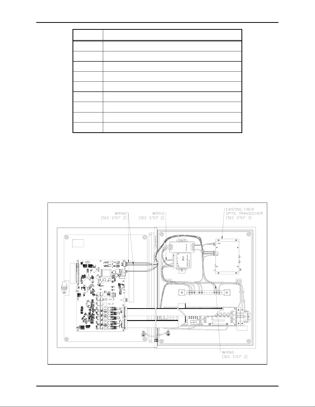
2. Disconnect the power wiring that runs from the Fiber Optic Transceiver and 12 V dc power supply,
and save for later use. Disconnect the data cable that runs from the Fiber Optic Transceiver to P19
on the Line Extender Main PCBA and discard. Remove the ground wire that runs from the Fiber
Optic Transceiver to the grounding bar and discard. Refer to Figure 1.
f:\standard ioms - current release\42003 kit manuals\42003-242a.doc
05/11
Figure 1.
Page 3

Pub. 42003-242A
M
ODEL 12549-001 AND 12549-002 LE200 FIBER MODULE MODIFICATION KITS Page: 3 of 4
3. Remove the four screws holding the Fiber Optic Transceiver to the rear mounting panel. Remove the
Fiber Optic Transceiver from the enclosure and discard. See Figure 1.
4. Using the #6-32 × 3/8-inch long flat head screws, mount the Line Extender adapter plate to the
enclosure.
5. Slide the Fiber Optic Module into the media chassis via the card guides until the module is seated
securely in the connector. Secure the module to the chassis by tightening the captive screws.
6. Mount the wall-mount brackets to the media chassis using the supplied screws.
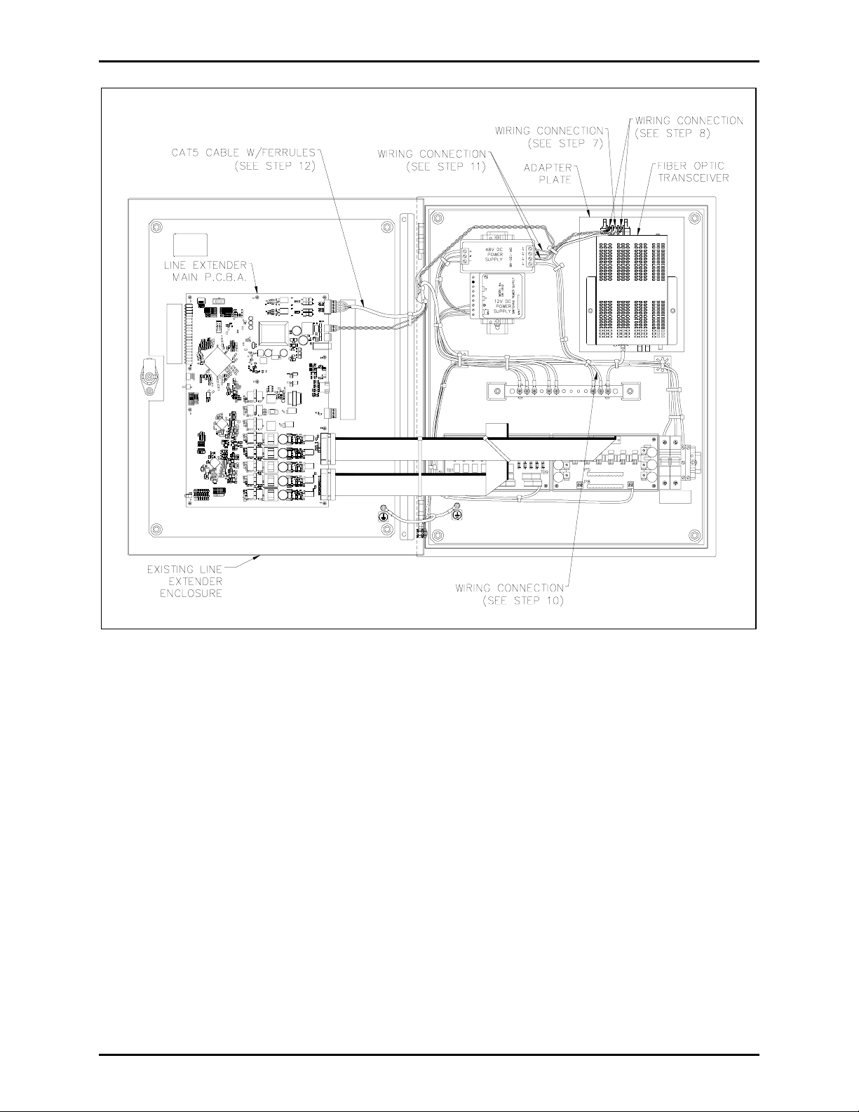
7. Using the supplied green/yellow wire, connect the ring lug to one end and connect a #6 14–16 AWG
spade terminal to the opposite end. Connect the spade terminal of the green/yellow wire to ground
on the new Fiber Optic Transceiver before installation into the enclosure. See Figure 2.
8. Using the red and black twisted pair wires previously saved, on one end replace the ferrule on each of
the wires with a #6 22–16 AWG spade terminal. Using the side with the spade terminals, connect the
red wire to the “+” terminal and the black wire to the “–” terminal at the new Fiber Optic Transceiver
before installation into the enclosure. See Figure 2.
9. Mount the new Fiber Optic Transceiver to the Line Extender adapter plate using two #8-32 nuts.
10. Connect the green/yellow wire coming from the new Fiber Optic Module to the grounding bar.
11. At the 48 V dc power supply, disconnect the black wire at the V– termination. Remove the existing
ferrule. Combine this black wire with the black wire coming from the new Fiber Optic Transceiver
and attach the supplied twin 2 × 18–20 AWG ferrule. Connect this ferrule back to the V–
termination at the 48 V dc power supply. Connect the red wire coming from the new Fiber Optic
Transceiver to the V+ termination at the 48 V dc power supply. See Figure 2.
12. Install the CAT5 cable with ferrules to the connector P19 on the Line Extender Main PCBA as
described below. Plug the RJ45 connector into the Fiber Optic Transceiver. Refer to Figure 2.
• White/orange wire to position 1 (TX-Ring)
• Orange wire to position 2 (TX-Tip)
• Blue wire to position 3 (RX – Ring)
• White/blue wire to position 4 (RX – Tip)
Connect the other end to the T1/E1 connection at the new Fiber Optic Transceiver.
13. Use tie cables wherever is necessary. Refer to Figure 2.
f:\standard ioms - current release\42003 kit manuals\42003-242a.doc
05/11
Page 4
Pub. 42003-242A
M
ODEL 12549-001 AND 12549-002 LE200 FIBER MODULE MODIFICATION KITS Page: 4 of 4
Figure 2.
f:\standard ioms - current release\42003 kit manuals\42003-242a.doc
05/11
 Loading...