

GAI-Tronics 12538-xxx User Manual

Pub. 42003-221A
GAI-TRONICS® CORPORATION
A HUBBELL COMPANY
Speaker Kit and Vacancy Kit
Model 12538-xxx & Model 12539-xxx
Confidentiality Notice
This manua l is provide d sole ly as an operatio nal, installation, and ma inte nance guide and conta ins
sensitive business and t e chnical informatio n tha t is confidentia l and pr opri et ary to GAI- Tronics.
GAI-Tronics retains all intellectual property and other rights in or to the information contained herein,
and such information may only be used in connection with the operation of your GAI-Tronics product or
system. This manu al may not be dis clos e d in any form, in whole or in pa rt, direct ly or i ndir ectly, to a ny
third pa r ty.
General Information
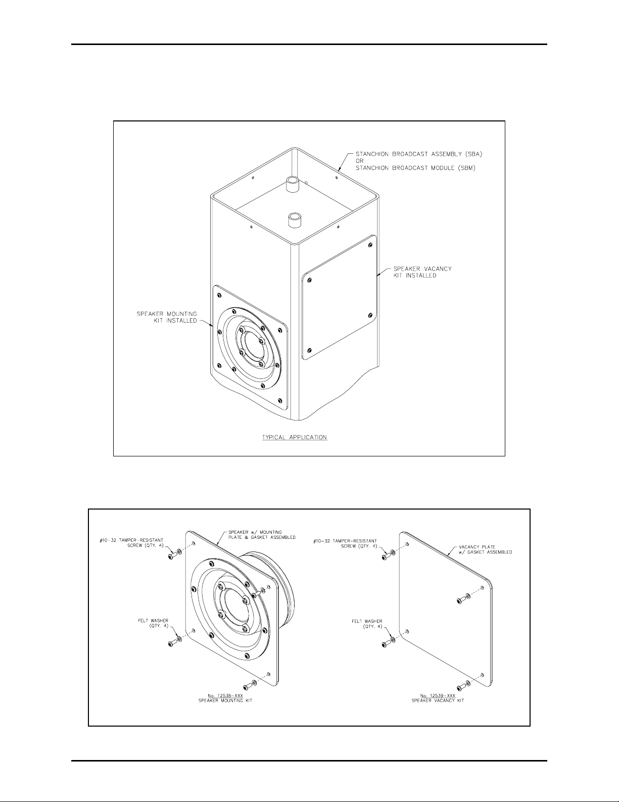
The Model 12538-xxx Speaker Kit is intended for use with a Model 234SBM Stanchion Broadcast
Module or a Model 234SBA Stanchion Broadcast Assembly. Each speaker kit consists of a weatherproof
speaker mounted to a gasketed plate and wiring harness to connect to the 10458-xxx Electronics Paging
Module.
Qty Description
1 Speaker Assembly
4 #10-32 tamper-resistant screws
4 Washers, felt
The Model 12539-xxx Vacancy Kit is also used with a Model 234SBM Stanchion Broadcast Module or a
Model 234SBA Stanchion Broadcast Assembly. The vacancy kit is used when less than four speakers are
needed in the stanchion.
Qty Description
1 Vacancy Panel Assembly
4 #10-32 tamper-resistant screws
4 Washers, felt
Installation
1. Inst all t he sp eaker kit or vacancy kit into the st anch ion or broadca st module in the desired direct ion,
carefully f eed i n g wires down to the access pa n el cut out for co nnection to the electronics module.
2. Secure each speaker panel with the four #10-32 tamper-resistant screws and felt washers provided.
GAI-Tronics Corporation 400 E. Wyomissing Av e. Mohnton, PA 19540 USA
610-777-1374 800-492-1212 Fax: 610-796-5954
ISIT WWW.GAI-TRONICS.COM FOR PRODUCT LITERATURE AND MANUALS
V
Pub. 42003-221A
M
ODEL 12538-XXX SPEAKER KIT AND MODEL 12539-XXX VACANCY KIT Page: 2 of 2
3. For the Speaker Kit, remove the four-position connector from the speaker connection in the 10458-
xxx Electronics Paging Module. Connect the BK/W and W/BK wires into the four-position
connector and plug into the speaker connection. Refer to Paging Module Instructions, Pub. 42004-
415.
Figure 1. Typical Appli c atio n of Speaker Kit and Va canc y Kit
Figu re 2. Expl oded View of Sp eaker K i t and Vaca ncy Kit
\\s_eng\gtc proddoc s \st andard iom s - current release\42003 kit manuals \ 42004-221a.doc
10/08
 Loading...