

Page 1
Pub. 42003-164A
GAI-TRONICS® CORPORATION
A HUBBELL COMPANY
SONIC ALARM™ Speaker
Pole Mounting Bracket Kit
MODEL 12537-001
Confidentiality Notice
This manual is pr ovided s olely as a n op erat ional, installation, and maintenance guide and contains sens itive
bus ines s and t echnic al infor ma tion tha t is confident i al and p roprietary to G AI-Tronics. GAI-Tronics
retains a ll intellectual pr operty and other rights in or to t he inf ormation c ontained herein, and s uch
informa tion may only be used in connection wit h the operation of you r GAI- Tronic s pr oduct or system.
This ma nual may not be disclosed in any form, in whole or in p art, dir ec tly or indirectly, to any t hird pa rty.
General Information
This kit is intended for the mounting of one or two speaker horns with 120° coverage on a single pole. A
single horn c an be mounted, or t wo horns can be st acked vertically and mounted as a u nit to the p ole. The
kit inclu des the following components:
Qty. Description Item No.
2 Mounting bracket 1
2 Speaker spacer bracket 2
2 Support bracket 3
12 Screw, hex head, 1/4-20 thread 4
24 Washer, flat, 1/4-inch 5
12 Lock washer, 1/4-inch 6
12 Nut, hex, 1/4-20 thread 7
Items 8- 11 ar e n o t supplied in this k it; however, they are referr ed to in thes e i n structio n s.
1 or 2 Model 13340 Horn with U-bracket and mounting hardware 8
1 or 2 Driver 9
1 Wood pole (s ee F igure 4 f or specif ic ations ) 10
10
NOTE: Mounting ha rdware is required b ased on the configur ation of the horn stac k. Use only hardware
that has a hot dip ped galva niz ed finish. L oc k washers and/or locking nu ts a re required.
Lag scr ew recommended. Size .50×2.0 inches long
11
GAI-Tronics Corporation P.O. Box 1060, Reading, PA 19607-1060 USA
610-777-1374 800-492-1212 Fax : 610-796-5954
ISIT WWW.GAI-TRONICS.COM FOR PRODUCT LITERATURE AND MANUALS
V
Page 2
Page: 2 of 7
ODEL 12537-001 SONIC ALARM™ SPEAKER POLE MOUNTING BRACKET Pub. 42003-164A
M
Installation
This kit may be used to inst all a variet y of speaker mount configura tions on a single pole. F or some
configurat ions, more than one kit is required. Additi onal hot dipped galva niz ed hardware may also be
required.
Mult iple bracket assemblies ma y be arranged horizontally around the pole and/or in vertical stacks. Up t o
three brackets assemblies, covering 120º each, can be located on a single level around a pole providing 360º
of coverage. In addition, the spea ker horn b rackets may be stac ked vertically at mu ltiple levels on a single
pole. T h e followi n g ar e some examples of possibl e ar rangements:
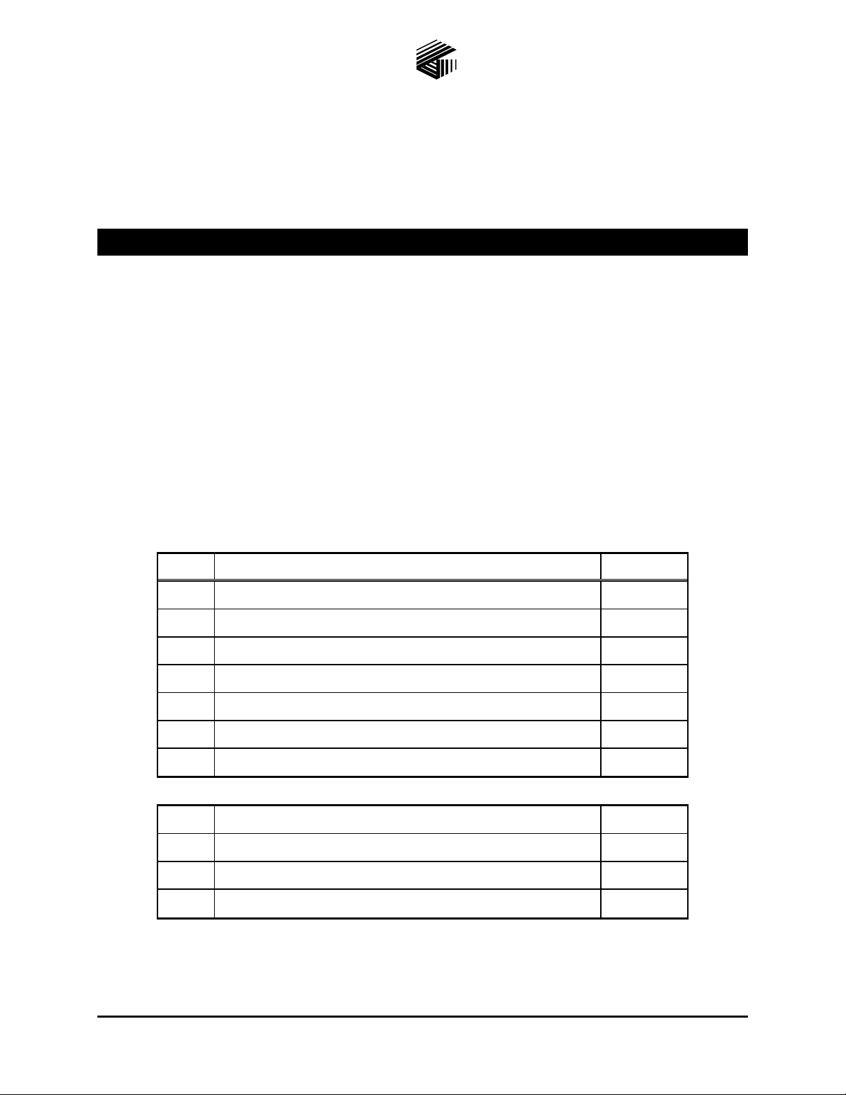
1. 360-1: In this arrangement, three mounting bra cket assemblies are arranged on a single level around
the pole for 360º of coverage. The speaker horns can be mounted on both levels of each bracket
assembly. This arrangement requires three Model 12537-001 kits. See Figure 1.
Figure 1. Arra ngement 360-1
\\s_eng\gtc proddoc s \ s tandard ioms - current release\ 42003 k it m anuals \42003-164a.doc
1/98
Page 3
Page: 3 of 7
ODEL 12537-001 SONIC ALARM™ SPEAKER POLE MOUNTING BRACKET Pub. 42003-164A
M
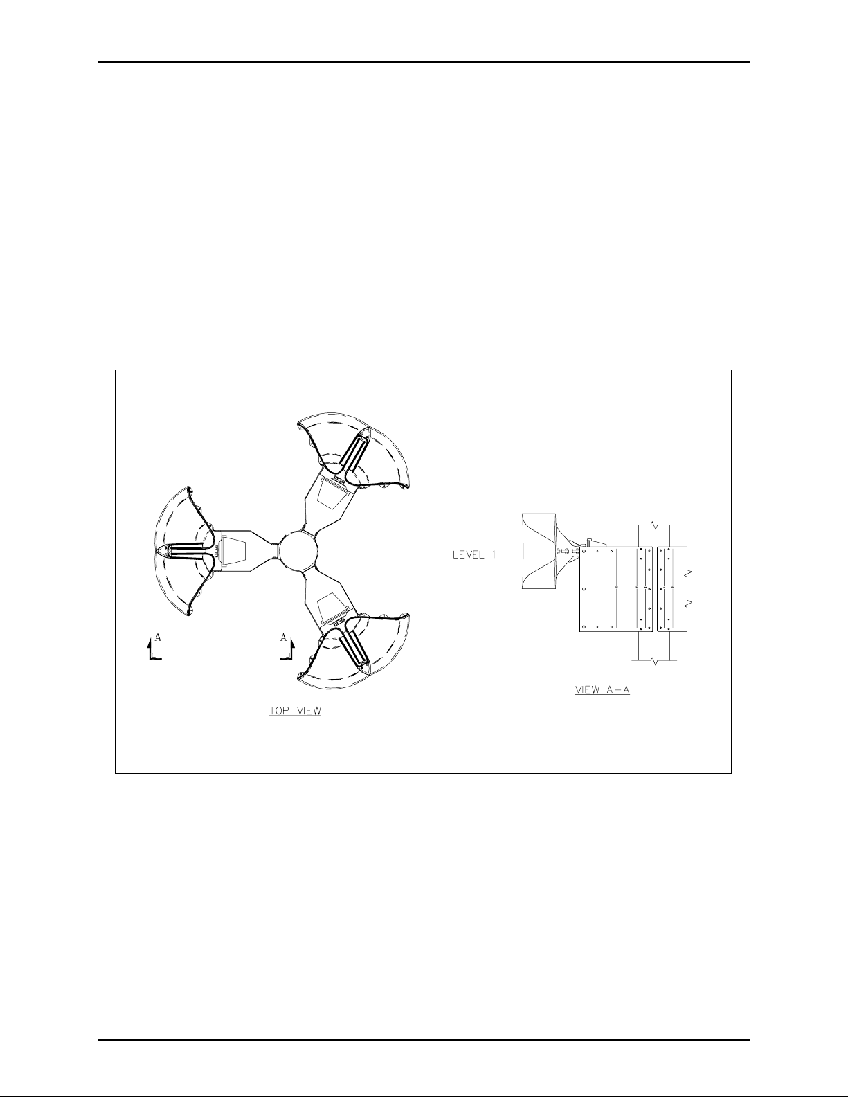
2. 240-2: In this arrangement two kits are used to mount two speaker brackets side by side for 240º of
covera ge. Four sp eaker hor ns may be mount ed in t his manner b y using both levels of the brac ket
assembly. T his configuration requires two kit s. S ee F igure 2.
Figure 2. Arra ngement 240-2
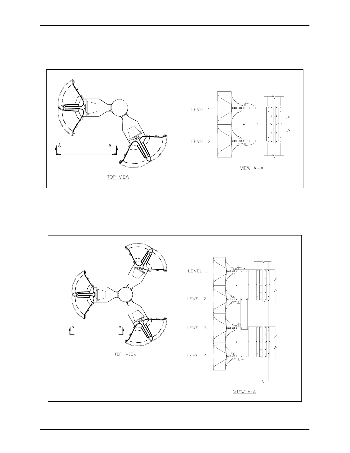
3. 360-4: This is a 360º arrangement where four levels of speakers are mounted in two 2-unit stacks.
This configur ation requires the use of s ix kits. See Figure 3.
Figure 3. Arra ngement 360-4.
\\s_eng\gtc proddoc s \ s tandard ioms - current release\ 42003 k it m anuals \42003-164a.doc
1/98
Page 4

Page: 4 of 7
ODEL 12537-001 SONIC ALARM™ SPEAKER POLE MOUNTING BRACKET Pub. 42003-164A
M
The combinations and configu rations pos sible a re:
120-1 120-2 120-3 120-4
240-1 240-2 240-3 240-4
360-1 360-2 360-3 360-4
Installation of One to Six Horns at One or Two Levels on a Single Pole
1. For each kit b eing u sed, assemble the mounti ng bra ckets (I tem No. 1) and sp eaker spacer brackets
(Item No. 2) using the screws, washers, and nuts (Item Nos. 4 to 7) as shown in Figure 4. Discard the
support brackets (Item No. 3) and any unused hardware.
OTE: Depending on the pers onnel and hoist equi pment ava ilable, the order of remaining st ep s may
N
vary.
2. Mount the bracket a ssembly fr om step 1 t o the pole. See F igure 4 and Figure 5. I f multiple kits are
being used, mount the additional a ssemblies.
3. Remove and disc ard the exist ing U-bracket f rom each horn (It em No. 8) t o be mounted. Reta in the U-
bracket screws, split lock washers, and star washers. (U-bracket not shown.)
4. Secure the hor n ( Item No. 8) to the bracket assembly ( see Figure 4 a nd Figure 5) using the hardware
from step 3. Repeat the assembly for each horn.
5. Secur e the driver (Item No. 9) to each horn, and wi re it per the system req uirements .
Installation of Three to 12 Horns at Three or More Levels on a Single Pole
The number of Model 12537-001 kits required depends on the mounting configuration selected. For
example:
• Mounting 12 horns at four levels around the perimeter of the pole for 360° of coverage requires six
kits. (See F igure 3.)
• Mounting six horns at three levels for 240° of coverage requires four kits.
• Mounting four horns at four levels for 120° of coverage requires two kits.
1. For each kit b eing u sed, assemble the mounti ng bra ckets (I tem No. 1) and sp eaker spacer brackets
(Item No. 2) using screws, washers, and nuts (Item Nos. 4 to 7). See Figure 4.
2. On one of the bracket assemblies, attach the support brackets (Item No. 3) using screws, washers, and
nuts (Item Nos. 4 to 7) as shown in Figure 6.
3. Bolt both br acket assemblies together using sc rews, washer s, and nuts (It em Nos . 4 t o 7) as shown in
Figure 6. Disc ard any unu sed hardware.
4. Repeat step s 2 a nd 3 for eac h additional stacked pa ir of kits to be ins talled.
5. Mount the bracket assemblies from step 1 to the pole. See Figure 4 and Figure 6.
6. Perf orm step s 3 through 5 in the “Ins tallation of O ne to Six H orns” section a bove.
\\s_eng\gtc proddoc s \ s tandard ioms - current release\ 42003 k it m anuals \42003-164a.doc
1/98
Page 5

Page: 5 of 7
ODEL 12537-001 SONIC ALARM™ SPEAKER POLE MOUNTING BRACKET Pub. 42003-164A
M
Figure 4. Installation of a single kit with 120º of coverage at two levels.
\\s_eng\gtc proddoc s \ s tandard ioms - current release\ 42003 k it m anuals \42003-164a.doc
1/98
Page 6

Page: 6 of 7
ODEL 12537-001 SONIC ALARM™ SPEAKER POLE MOUNTING BRACKET Pub. 42003-164A
M
Figure 5. Showing the use of a s i ngle kit to st ack one (or two) sp eaker horns.
\\s_eng\gtc proddoc s \ s tandard ioms - current release\ 42003 k it m anuals \42003-164a.doc
1/98
Page 7

Page: 7 of 7
ODEL 12537-001 SONIC ALARM™ SPEAKER POLE MOUNTING BRACKET Pub. 42003-164A
M
Figure 6. Showing the use of two single kits to sta c k three (or four) speaker horns.
\\s_eng\gtc proddoc s \ s tandard ioms - current release\ 42003 k it m anuals \42003-164a.doc
1/98
Page 8

Warranty
Equipment. GAI-Tronics warrants for a period of one (1) year from the date of shipment, that any
GAI-Tronics equipment supplied hereunder shall be free of defects in material and workmanship, shall
comply with the then-current product specifications and product literature, and if applicable, shall be fit
for the purpose specified in the agreed-upon quotation or proposal document. If (a) Seller’s goods prove
to be defective in workmanship and/or material under normal and proper usage, or unfit for the purpose
specified and agreed upon, and (b) Buyer’s claim is made within the warranty period set forth above,
Buyer may return such goods to GAI-Tronics’ nearest depot repair facility, freight prepaid, at which time
they will be repaired or replaced, at Seller’s option, without charge to Buyer. Repair or replacement shall
be Buyer’s sole and exclusive remedy. The warranty period on any repaired or replacement equipment
shall be the greater of the ninety (90) day repair warranty or one (1) year from the date the original
equipment was shipped. In no event shall GAI-Tronics warranty obligations with respect to equipment
exceed 100% of the total cost of the equipment supplied hereunder. Buyer may also be entitled to the
manufacturer’s warranty on any third-party goods supplied by GAI-Tronics hereunder. The applicability
of any such third-party warranty will be determined by GAI-Tronics.
Services. Any services GAI-Tronics provides hereunder, whether directly or through subcontractors,
shall be performed in accordance with the standard of care with which such services are normally
provided in the industry. If the services fail to meet the applicable industry standard, GAI-Tronics will
re-perform such services at no cost to buyer to correct said deficiency to Company's satisfaction provided
any and all issues are identified prior to the demobilization of the Contractor’s personnel from the work
site. Re-performance of services shall be Buyer’s sole and exclusive remedy, and in no event shall GAITronics warranty obligations with respect to services exceed 100% of the total cost of the services
provided hereunder.
Warranty Periods. Every claim by Buyer alleging a defect in the goods and/or services provided
hereunder shall be deemed waived unless such claim is made in writing within the applicable warranty
periods as set forth above. Provided, however, that if the defect complained of is latent and not
discoverable within the above warranty periods, every claim arising on account of such latent defect shall
be deemed waived unless it is made in writing within a reasonable time after such latent defect is or
should have been discovered by Buyer.
Limitations / Exclusions. The warranties herein shall not apply to, and GAI-Tronics shall not be
responsible for, any damage to the goods or failure of the services supplied hereunder, to the extent
caused by Buyer’s neglect, failure to follow operational and maintenance procedures provided with the
equipment, or the use of technicians not specifically authorized by GAI-Tronics to maintain or service the
equipment. THE WARRANTIES AND REMEDIES CONTAINED HEREIN ARE IN LIEU OF AND
EXCLUDE ALL OTHER WARRANTIES AND REMEDIES, WHETHER EXPRESS OR IMPLIED BY
OPERATION OF LAW OR OTHERWISE, INCLUDING ANY WARRANTIES OF
MERCHANTABILITY OR FITNESS FOR A PARTICULAR PURPOSE.
Return Policy
If the equipment requires service, contact your Regional Service Center for a return authorization number
(RA#). Equipment should be shipped prepaid to GAI-Tronics with a return authorization number and a
purchase order number. If the equipment is under warranty, repairs or a replacement will be made in
accordance with the warranty policy set forth above. Please include a written explanation of all defects to
assist our technicians in their troubleshooting efforts.
Call 800-492-1212 (inside the USA) or 610-777-1374 (outside the USA) for help identifying the
Regional Service Center closest to you.
(Rev. 10/06)
 Loading...