

Page 1

Pub. 42003-228A
GAI-TRONICS® CORPORATION
A HUBBELL COMPANY
Speaker Assembly Replacement Kit for
Model 297 and 298 Series Telephones
Model 12522-005
Confidential ity Notice
This manual is provided solely as an operational, installation, and maintenance guide and contains
sensitive business and technical information that is confidential and proprietary to GAI-Tronics.
GAI-Tronics retains all intellectual property and other rights in or to the information contained herein,
and such information may only be used in connection with the operation of your GAI-Tronics product or
system. This manual may not be disclosed in any form, in whole or in part, directly or indirectly, to any
third party.
General Information
The Model 12522-005 Speaker Assembly Replacement Kit is designed for use with the GAI-Tronics
Model 297 and 298 Series Telephones. It includes the following components:
Qty Description
1 Speaker assembly
1 Tie wrap
Installation
Removal of Old Speaker Assembly
1. Use a Model 233-001 Tamper-Resistant Screwdriver to remove the six screws securing the front
panel assembly to the back box. Save the screws for reassembly.
2. Lift the front panel assembly approximately 6 to 8 inches away from the back box.
3. Unplug the telephone line cord from the modular block in the back box, or disconnect the telephone
line from TB1, depending on the installation.
4. Remove the front panel assembly and place it face down on a flat surface.
5. Use wire cutters to snip the tie wrap securing the push buttons (s) and speak er w ire.
6. Unplug the speaker assembly cable from the printed circuit board assembly (PCBA).
GAI-Tronics Corporation 400 E. Wyomissing Ave. Mohnton, PA 19540 USA
610-777-1374 800-492-1212 Fax: 610-796-5954
V
ISIT WWW.GAI-TRONICS.COM FOR PRODUCT LITERATURE AND MANUALS
Page 2
Pub. 42003-228A
ODEL 12522-005 SPEAKER ASSEMBLY REPLACEMENT KIT FOR MODEL 297 & 298 SERIES Page: 2 of 6
M
7. Use the #2 Phillips head screwdriver to remove the screws securing the PCBA to the standoffs. Save
the screws for reassembly.
8. Use the ¼-inch nut driver to remove the standoff and three hex nuts securing the speaker assembly to
the front panel assembly. Save them for reassembly. (If the telephone contains an adapter plate that
holds a 3.5 inch speaker, remove the nuts that allow the entire adapter plate/speaker combination to
be removed.)
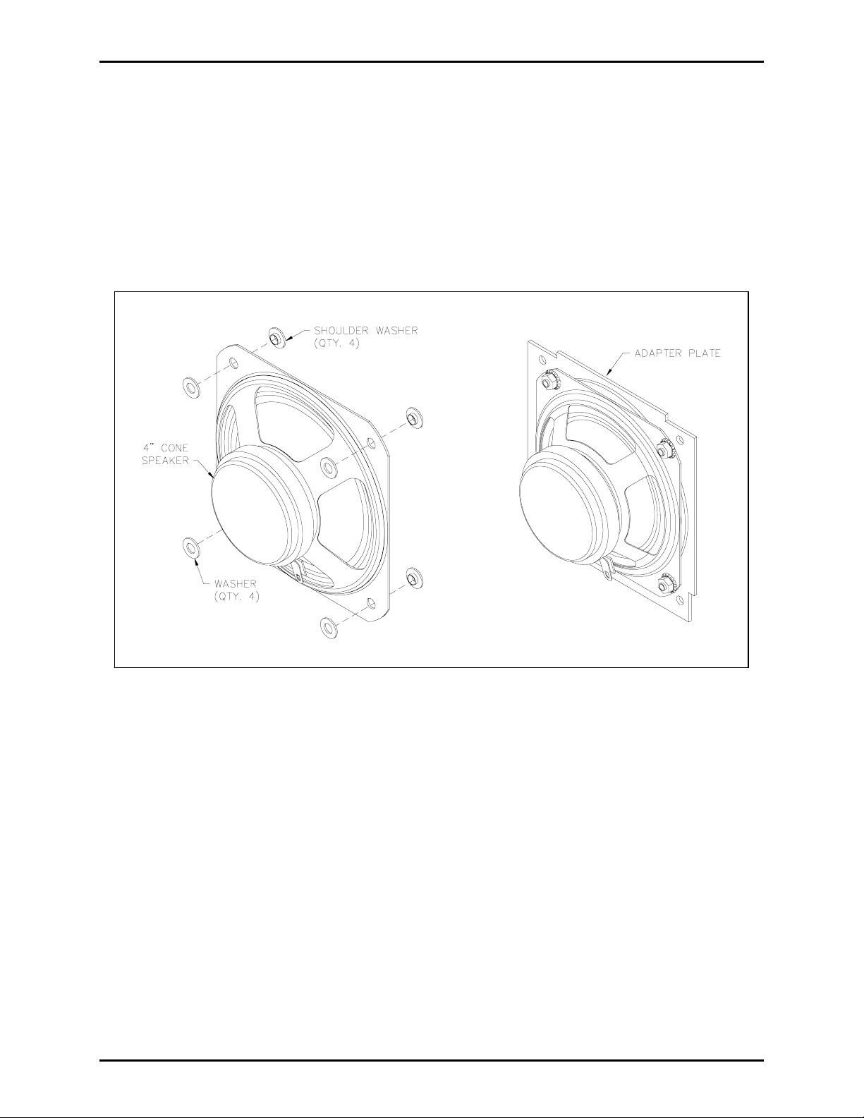
9. If present, remove the four flat nylon washers from the top of the speaker mounting holes. Remove
the four nylon shoulder washers from under the 4-inch speaker mounting holes. (These shoulder
washers can be dislodged with a small tool if they become embedded in the gasket material.)
Figure 1.
OTE: Discard the following used parts:
N
• Speaker assembly (including adapter plate, if present)
• Flat nylon washers
• Nylon shoulder washers
f:\standard ioms - current release\42003 kit manuals\42003-228a.doc
1109
Page 3
Pub. 42003-228A
ODEL 12522-005 SPEAKER ASSEMBLY REPLACEMENT KIT FOR MODEL 297 & 298 SERIES Page: 3 of 6
M
Installation of New Non-Metallic Piezo Speaker Assembly
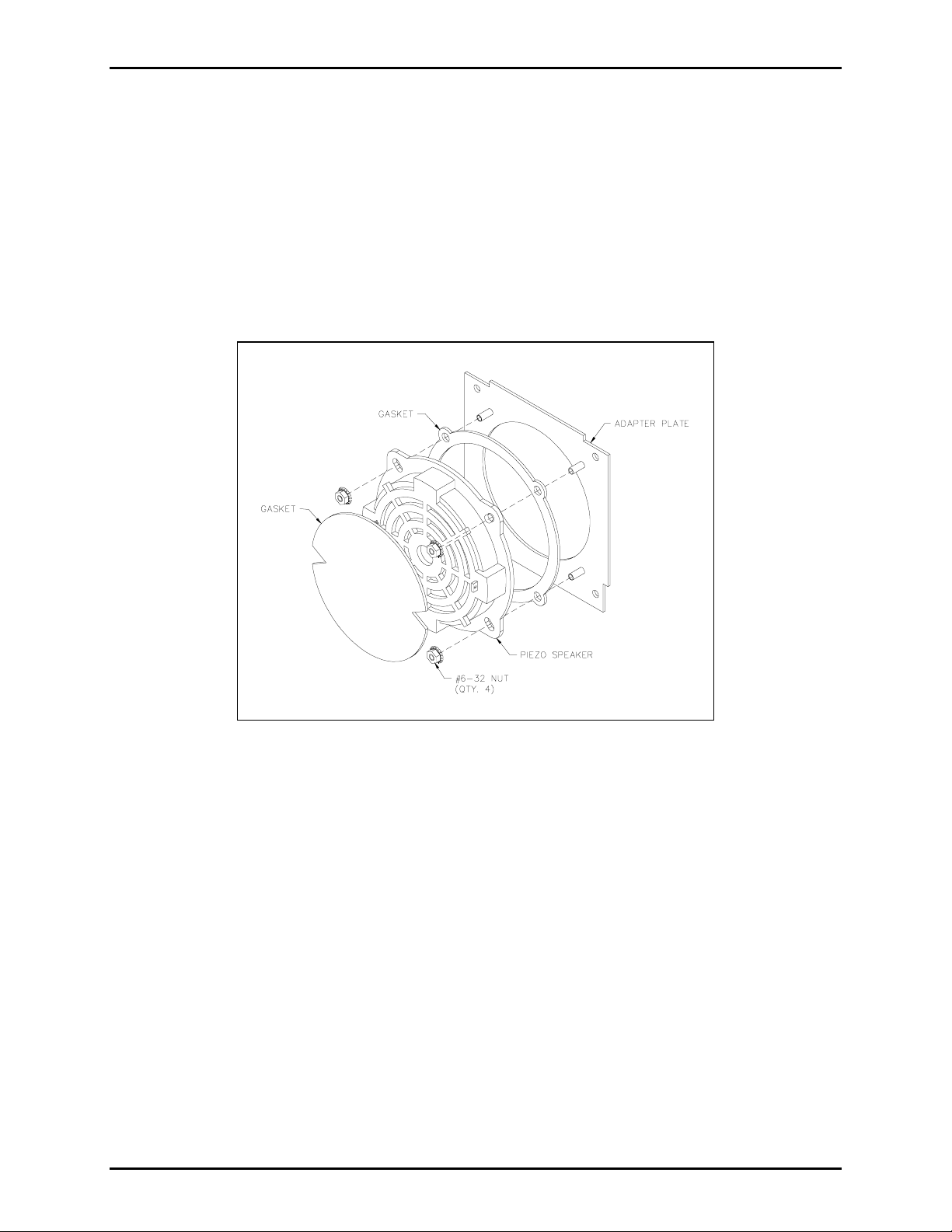
1. Place the new speaker assembly on the front panel mounting studs.
2. Use the ¼-inch nut driver to secure the adapter plate containing the non-metallic piezo speaker in
place with the 6-32 × 0.875-inch standoff and the three hex nuts.
3. Secure the PCBA in place with the previously saved screws and the Phillips screwdriver.
4. Plug the speaker assembly cable in the PCBA at J5.
5. Use the enclosed tie wrap to secure the push button and speaker cables together.
Figure 2. Piezo Speaker Installation
Required Adjustments
The speaker adjustments required for GAI-Tronics Model xxx–001 Phones are different from those for the
Model xxx-003 S.M.A.R.T. Phones.
Adjustment for Model 297-001 and 298-001 Phones
NOTE: This section also applies to other GAI-Tronics standard emergency telephones, such as the Model
GTJ09030.
1. Adjust the audio settings either by local programming or by remote programming. For local
programming, a keypad is required. (Part No. 51035-011 Keypad and 61504-048 Keypad Cable
Assembly are sold separately).
2. Connect the telephone having the new speaker to its telephone line where it can be easily called with
another Touch-Tone phone, or be programmed locally).
f:\standard ioms - current release\42003 kit manuals\42003-228a.doc
1109
Page 4

Pub. 42003-228A
ODEL 12522-005 SPEAKER ASSEMBLY REPLACEMENT KIT FOR MODEL 297 & 298 SERIES Page: 4 of 6
M
For Single Button Emergency Phones – Local Programming
1. Disconnect the EMERGENCY push button from J7, the “Emerg PB” socket on the phone PCBA.
2. Connect the E
MERGENCY push button to J1, the “Call PB” socket on the phone PCBA.
3. Note the positions of jumpers J14 and J9. On the PCBA, enable auto-answer by placing a jumper
between pins 2 and 3 on J14 and disable password protection by removing the jumper from J9.
4. Connect a keypad to J13. (Part No. 51035-011 Keypad and 61504-048 Keypad Cable Assembly are
sold separately).
5. Press the EMERGENCY button. After you hear the dial tone, simulta neou sly press the 1 and # keys.
After you hear the confirmation tone, enter the command #2330; then enter the command #77017;
and then enter the command #79009. (A single beep after each command indicates success.) To
hang up the phone, press the E
6. Press the E
MERGENCY push button.
MERGENCY button or wait 30 seconds for the phone to time out.
7. The dial tone you hear may be pulsing, but the phone is adjusting itself to compensate. When the dial
tone is steady (with no volume variations), the process is complete. Depending on the phone line and
the duration dial tone, it may be necessary to repeat this step one or more times.
8. Disconnect the E
9. Reconnect the E
MERGENCY push button from J1, the “Call PB” socket on the phone PCBA.
MERGENCY push button to J7, the “Emerg PB” socket on the phone PCBA.
10. Return the jumpers adjusted in step 3 to their original positions. Configure the phone for auto-answer
and password protection as required. Refer to the “Programming” section of the original phone
manual for additional details.
11. Disconnect the keypad from J13.
12. Install the phone in the back box or enclosure.
For Emergency Phones with a CALL Push Button and Keypad - Local Programming
1. Note the position of jumper J9. Disable password protection by removing the jumper from J9.
2. Press the C
ALL button. After you hear the dial tone, simultaneously press the 1 and # keys. After
you hear the confirmation tone, enter the command #2324; then enter the command #77017; and then
enter the command #79009.
phone, press the C
3. Press the C
ALL push button. The dial tone you hear may be pulsing, but the phone is adjusting itself
ALL button or wait 30 seconds for the phone to time out.
(A single beep after each command indicates success.) To hang up the
to compensate. When the dial tone is steady (with no volume variations), the process is complete.
Depending on the phone line and the duration of dial tone, it may be necessary to repeat this step one
or more times.
4. Return the J9 jumper adjusted in step 1) to its orig ina l posi tio n.
f:\standard ioms - current release\42003 kit manuals\42003-228a.doc
1109
Page 5

Pub. 42003-228A
ODEL 12522-005 SPEAKER ASSEMBLY REPLACEMENT KIT FOR MODEL 297 & 298 SERIES Page: 5 of 6
M
5. The speaker volume may also be adjusted using R106 after installation. Please refer to the uni t’s
original installation and user manual for details.
6. Secure the front panel assembly to the back box with the saved screws using the Model 233-001
Tamper-Resistant Screwdriver.
For Model
xxx
-001 Series Emergency Phones – Remote Programming with Password Enabled
1. For remote programming, a Touch-Tone (DTMF) telephone connected to a separate central office
(CO) or private branch exchange (PBX) line is required.
2. Enable the password protection feature—insert the J9 jumper on pins 2 and 3.
3. Enable the auto-answer feature—insert the J14 jumper on pins 2 and 3.
4. Using a Touch-Tone telephone, call the emergency telephone. The emergency telephone
automatically answers the call and generates a splash tone followed by a success tone (single beep).
5. Dial the four-digit password. If the password has not been altered, dial the password 2468 (factory
setting). Otherwise, dial the preprogrammed user password. A success tone (single beep) is
generated to indicate that the password has been accepted and that programming mode has been
accessed.
OTES:
N
• The telephone automatically times out if 20 seconds elapse between digit entries, or if an invalid
password is entered.
• If DTMF digits have not been dialed within 3 seconds of the call initiation, the telephone remains
off-hook and the programming mode is terminated.
6. After you hear the success tone, enter the command #2324; then enter the command #77017; and then
enter the command #79009.
phone, press the C
ALL button or wait 30 seconds for the phone to time out.
(A single beep after each command indicates success.) To hang up the
7. If the phone has a C
ALL button, press the CALL push button. The dial tone you hear may be pulsing,
but the phone is adjusting itself to compensate. When the dial tone is steady (with no volume
variations), the process is complete. Depending on the phone line and the duration of dial tone, it
may be necessary to repeat this step one or more times.
8. The speaker volume may also be adjusted using R106 after installation. Please refer to the uni t’s
original installation and user manual for details.
9. Secure the front panel assembly to the back box with the saved screws using the Model 233-001
Tamper-Resistant Screwdriver.
f:\standard ioms - current release\42003 kit manuals\42003-228a.doc
1109
Page 6

Pub. 42003-228A
ODEL 12522-005 SPEAKER ASSEMBLY REPLACEMENT KIT FOR MODEL 297 & 298 SERIES Page: 6 of 6
M
Adjustment for Model 297-003 and 298-003 Phones
NOTE: This section also applies to other GAI-Tronics standard emergency telephones, such as the Model
GTK06010, GTD06025 and similar phones.
1. Locate a white label on the telephone’s circuit board (near a green terminal block). Confirm that this
label indicates “V135” or greater. If it does not, contact your GAI-Tronics Regional Service Center.
2. Connect the telephone having the new speaker to a “test” telephone line near the TMA PC. TMA will
be used to adjust settings in this phone for best audio performance. (If it is more convenient, connect
the phone to its normal location at this step, and secure the front panel assembly to the back box with
the saved screws using the Model 233-001 Tamper-Resistant Screwdriver.)
3. Using a PC that has access to the Internet, view the GAI-Tronics home page located at www.gai-
tronics.com. Select either the “Document Center” link or the “Manuals and Specifications” link, then
select “Kit Manuals”. On this page, locate the 42003-228 manual for this Model 12522-005 Kit.
Right click on the link in the right column (-003 SMART Phones Update File) and select Save Target
As to download the file “001_006_GLOBAL.xml”. Store this file on the TMA PC in the folder
C:\TMAXML\XMLConfiguration.
4. With TMA, right click on the phone icon (type GTC SMART Handsfree – “yellow box”) that
corresponds to the phone line that connects to this updated S.M.A.R.T. telephone. Select Phone
Management Form. Navigate to the Behavior settings (by clicking on the word “Behavior” near
upper left).
5. Move the Audio Receive Level slider to 0, and then to 15 for this non-metallic-frame piezo-type
speaker. (The setting for the metallic- frame cone type speaker is 12 or less.)
6. Click the
7. Click the
Send and the Synchronize Now radio buttons.
Apply button, and then click the OK button.
8. Using the SPI Client “Call Status” window, observe the progress of this maintenance call. Changes
will be made to EEPROM locations 30d and 28d near the end of the poll call. These settings changes
are specified in the “GLOBAL” XML document copied in step 3. See note below for additional
details.
9. After the maintenance call ends, delete the file “001_006_GLOBAL.xml” from the folder
C:\TMAXML\XMLConfiguration. Deleting this file prevents these updates from being made on
subsequent maintenance calls, which can affect phones that do not need these updates.
10. If the phone is connected to a “test” location, re-install the telephone in its normal location. The
speaker volume may need to be adjusted after installation.
11. Secure the front panel assembly to the back box with the saved screws using the Model 233-001
Tamper-Resistant Screwdriver.
OTE: Double-click the telephone icon in the Windows system tray to display the SPI’s Call Status
N
window. This will allow for viewing the progress of a maintenance call with a S.M.A.R.T. phone. This
SPI call status window may be visible, or may be hidden; in either case, the SPI can run normally,
processing calls at the request of the main TMA application.
If you have questions or need further assistance, please contact GAI-Tronics at 800-492-1212 inside the
USA or 610-777-1374 outside the USA.
f:\standard ioms - current release\42003 kit manuals\42003-228a.doc
1109
Page 7

Warranty
Equipment. GAI-Tronics warrants for a period of one (1) year from the date of shipment, that any
GAI-Tronics equipment supplied hereunder shall be free of defects in material and workmanship, shall
comply with the then-current product specifications and product literature, and if applicable, shall be fit
for the purpose specified in the agreed-upon quotation or proposal document. If (a) Seller’s goods prove
to be defective in workmanship and/or material under normal and proper usage, or unfit for the purpose
specified and agreed upon, and (b) Buyer’s claim is made within the warranty period set forth above,
Buyer may return such goods to GAI-Tronics’ nearest depot repair facility, freight prepaid, at which time
they will be repaired or replaced, at Seller’s option, without charge to Buyer. Repair or replacement shall
be Buyer’s sole and exclusive remedy. The warranty period on any repaired or replacement equipment
shall be the greater of the ninety (90) day repair warranty or one (1) year from the date the original
equipment was shipped. In no event shall GAI-Tronics warranty obligations with respect to equipment
exceed 100% of the total cost of the equipment supplied hereunder. Buyer may also be entitled to the
manufacturer’s warranty on any third-party goods supplied by GAI-Tronics hereunder. The applicability
of any such third-party warranty will be determined by GAI-Tronics.
Services. Any services GAI-Tronics provides hereunder, whether directly or through subcontractors,
shall be performed in accordance with the standard of care with which such services are normally
provided in the industry. If the services fail to meet the applicable industry standard, GAI-Tronics will
re-perform such services at no cost to buyer to correct said deficiency to Company's satisfaction provided
any and all issues are identified prior to the demobilization of the Contractor’s personnel from the work
site. Re-performance of services shall be Buyer’s sole and exclusive remedy, and in no event shall GAITronics warranty obligations with respect to services exceed 100% of the total cost of the services
provided hereunder.
Warranty Periods. Every claim by Buyer alleging a defect in the goods and/or services provided
hereunder shall be deemed waived unless such claim is made in writing within the applicable warranty
periods as set forth above. Provided, however, that if the defect complained of is latent and not
discoverable within the above warranty periods, every claim arising on account of such latent defect shall
be deemed waived unless it is made in writing within a reasonable time after such latent defect is or
should have been discovered by Buyer.
Limitations / Exclusions. The warranties herein shall not apply to, and GAI-Tronics shall not be
responsible for, any damage to the goods or failure of the services supplied hereunder, to the extent
caused by Buyer’s neglect, failure to follow operational and maintenance procedures provided with the
equipment, or the use of technicians not specifically authorized by GAI-Tronics to maintain or service the
equipment. THE WARRANTIES AND REMEDIES CONTAINED HEREIN ARE IN LIEU OF AND
EXCLUDE ALL OTHER WARRANTIES AND REMEDIES, WHETHER EXPRESS OR IMPLIED BY
OPERATION OF LAW OR OTHERWISE, INCLUDING ANY WARRANTIES OF
MERCHANTABILITY OR FITNESS FOR A PARTICULAR PURPOSE.
Return Policy
If the equipment requires service, contact your Regional Service Center for a return authorization number
(RA#). Equipment should be shipped prepaid to GAI-Tronics with a return authorization number and a
purchase order number. If the equipment is under warranty, repairs or a replacement will be made in
accordance with the warranty policy set forth above. Please include a written explanation of all defects to
assist our technicians in their troubleshooting efforts.
Call 800-492-1212 (inside the USA) or 610-777-1374 (outside the USA) for help identifying the
Regional Service Center closest to you.
(Rev. 10/06)
 Loading...