

Page 1

Pub. 42003-199B
GAI-TRONICS® CORPORATION
A HUBBELL COMPANY
Speaker Ass embly Replacement Kit
MODEL 12522-003
Confidentiality Notice
This ma nual is p rovided solely as an operat ion, inst allation, and maintena nc e gu ide and contains sens itive
bus ines s and t echnic al infor ma tion tha t is confident ial and prop rieta ry to GAI - Tr onic s. GAI- Tr onic s retains
all intellectual prop erty a nd other r ights in or to the information contained herein, and s uch infor ma tion may
only be used in connection with t he op erat ion of your GAI-T ronics produ c t or s ystem. This manu al may not
be disclos ed in any form, in whole or in pa rt, direct ly or indirectly, t o any third party.
General Information
This kit is to b e u sed in the following GAI-Tr onic s Emergency phones:
• 293-003 • 294AL-003 • 298-003 • 293AL-001 • 297-001
• 293AL-003 • 297-003 • 293-001 • 294AL-001 • 298-001
This kit contains t he following:
Qty Description
1 Weatherproof speaker, 3.5-inch, 45- ohm, with connector
1 Tie wrap
The following t ools ar e required:
• ¼-inch hex nut dr iver or s ocket wrench
• Model 233 Tamper-Resistant Screwdriver
• #2 P hillip s scr ewdr iver
Installation (Models 297- 00x and 298-00x)
Removing the Old Speaker Assembly
CAUTION
1. Use a Model 233 Tamper-resistant Screwdriver to remove the screws securing the front panel assembly
to the back box. Save these screws for re-assembly.
Disconnect the phone line.
GAI-Tronics Corporation P.O. Box 1060, Reading, PA 19607-1060 USA
610-777-1374 800-492-1212 Fax : 610-796-5954
ISIT WWW.GAI-TRONICS.COM FOR PRODUCT LITERATURE AND MANUALS
V
Page 2
Page: 2 of 4
ODEL 12522-003 SPEAKER ASSEMBLY REPLACEMENT KIT Pub. 42003-199B
M
2. If necess ary, snip the tie wrap s ecuring the following wires to each other: s p eaker, pus h button(s) , LED
indicat or, and in some cases, microphones.
3. Recor d the locat i on of each connect ion to the PCBA (to aid in the connection of the r ep l acement
PCB A) as you unplug all the connectors.
4. Remove the 4 sc rews holding t he PCBA, and set the PCB A to the side.
These models eac h have a s hield t hat first mu st be removed.
Note:
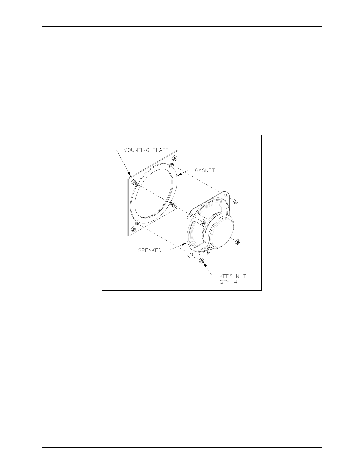
5. Remove the four 6-32 Keps nuts attaching the speaker to the speaker-mounting plate. Refer to Figure
1.
6. Remove the speaker a nd discard.
Figure 1. Models 297-xxx and 298-xxx
Installing the New Speaker Assembly
1. Attach the new speaker assembly with the original 6-32 Keps nuts, carefully applying equal pressure to
all four corners of the speakers.
2. Reattac h the PCBA and shield using the original screws.
3. Plug in all of the connectors to the PCBA in their original loc ations .
4. Use the supplied tie wrap to secure the speaker assembly wire, as necessary.
5. Reatta ch the fr ont cover.
\\s_eng\gtc proddoc s \ s tandard ioms - current release\ 42003 k it m anuals \42003-199b.doc
01/04
Page 3

Page: 3 of 4
ODEL 12522-003 SPEAKER ASSEMBLY REPLACEMENT KIT Pub. 42003-199B
M
Installation (Models 293- 00x, 293AL-00x, & 294AL-00x)
Removing the Old Speaker Assembly
CAUTION
Disconnect the phone line.
1. Use a Model 233 Tamper-resistant Screwdriver to remove the screws securing the front panel assembly
to the back box. Save these screws for re-assembly.
2. If necess ary, snip the tie wrap s ecuring the following wires to each other: s p eaker, pus h button(s) , LED
indicat or, and in some cases, microphones.
3. Recor d the locat i on of each connect ion to the PCBA (to aid in the connection of the r ep l acement
PCB A) as you unplug all the connectors.
4. Remove the 4 sc rews holding t he PCBA, and set the PCB A to the side.
5. Remove the four #6 screws attaching the speaker to the speaker-mounting plate. Refer to Figure 2.
6. Remove the speaker a nd discard.
Figure 2. Models 293-xxx, 293AL-xxx, and 294AL-xxx
\\s_eng\gtc proddoc s \ s tandard ioms - current release\ 42003 k it m anuals \42003-199b.doc
01/04
Page 4

Page: 4 of 4
ODEL 12522-003 SPEAKER ASSEMBLY REPLACEMENT KIT Pub. 42003-199B
M
Installing the New Speaker Assembly
1. Attach the new spea ker as sembly with the original #6 screws, ca refully a pplying equa l press ure to all
fou r corners of the speakers.
2. Reattac h the PCBA and shield using the original screws.
3. Plug in all of the connectors to the PCBA in their original loc ations .
4. Use the supplied tie wrap to secure the speaker assembly wire, as necessary.
5. Reatta ch the fr ont cover.
\\s_eng\gtc proddoc s \ s tandard ioms - current release\ 42003 k it m anuals \42003-199b.doc
01/04
Page 5

Warranty
Equipment. GAI-Tronics warrants for a period of one (1) year from the date of shipment, that any
GAI-Tronics equipment supplied hereunder shall be free of defects in material and workmanship, shall
comply with the then-current product specifications and product literature, and if applicable, shall be fit
for the purpose specified in the agreed-upon quotation or proposal document. If (a) Seller’s goods prove
to be defective in workmanship and/or material under normal and proper usage, or unfit for the purpose
specified and agreed upon, and (b) Buyer’s claim is made within the warranty period set forth above,
Buyer may return such goods to GAI-Tronics’ nearest depot repair facility, freight prepaid, at which time
they will be repaired or replaced, at Seller’s option, without charge to Buyer. Repair or replacement shall
be Buyer’s sole and exclusive remedy. The warranty period on any repaired or replacement equipment
shall be the greater of the ninety (90) day repair warranty or one (1) year from the date the original
equipment was shipped. In no event shall GAI-Tronics warranty obligations with respect to equipment
exceed 100% of the total cost of the equipment supplied hereunder. Buyer may also be entitled to the
manufacturer’s warranty on any third-party goods supplied by GAI-Tronics hereunder. The applicability
of any such third-party warranty will be determined by GAI-Tronics.
Services. Any services GAI-Tronics provides hereunder, whether directly or through subcontractors,
shall be performed in accordance with the standard of care with which such services are normally
provided in the industry. If the services fail to meet the applicable industry standard, GAI-Tronics will
re-perform such services at no cost to buyer to correct said deficiency to Company's satisfaction provided
any and all issues are identified prior to the demobilization of the Contractor’s personnel from the work
site. Re-performance of services shall be Buyer’s sole and exclusive remedy, and in no event shall GAITronics warranty obligations with respect to services exceed 100% of the total cost of the services
provided hereunder.
Warranty Periods. Every claim by Buyer alleging a defect in the goods and/or services provided
hereunder shall be deemed waived unless such claim is made in writing within the applicable warranty
periods as set forth above. Provided, however, that if the defect complained of is latent and not
discoverable within the above warranty periods, every claim arising on account of such latent defect shall
be deemed waived unless it is made in writing within a reasonable time after such latent defect is or
should have been discovered by Buyer.
Limitations / Exclusions. The warranties herein shall not apply to, and GAI-Tronics shall not be
responsible for, any damage to the goods or failure of the services supplied hereunder, to the extent
caused by Buyer’s neglect, failure to follow operational and maintenance procedures provided with the
equipment, or the use of technicians not specifically authorized by GAI-Tronics to maintain or service the
equipment. THE WARRANTIES AND REMEDIES CONTAINED HEREIN ARE IN LIEU OF AND
EXCLUDE ALL OTHER WARRANTIES AND REMEDIES, WHETHER EXPRESS OR IMPLIED BY
OPERATION OF LAW OR OTHERWISE, INCLUDING ANY WARRANTIES OF
MERCHANTABILITY OR FITNESS FOR A PARTICULAR PURPOSE.
Return Policy
If the equipment requires service, contact your Regional Service Center for a return authorization number
(RA#). Equipment should be shipped prepaid to GAI-Tronics with a return authorization number and a
purchase order number. If the equipment is under warranty, repairs or a replacement will be made in
accordance with the warranty policy set forth above. Please include a written explanation of all defects to
assist our technicians in their troubleshooting efforts.
Call 800-492-1212 (inside the USA) or 610-777-1374 (outside the USA) for help identifying the
Regional Service Center closest to you.
(Rev. 10/06)
 Loading...