

Page 1

Pub. 42003-224A
GAI-TRONICS® CORPORATION
A HUBBELL COMPANY
Microphone Assembly Replacement Kit
for 293 & 294 Series Phones
Model 12521-002
Confidential ity Notice
This manual is provided solely as an operational, installation, and maintenance guide and contains
sensitive business and technical information that is confidential and proprietary to GAI-Tronics.
GAI-Tronics retains all intellectual property and other rights in or to the information contained herein,
and such information may only be used in connection with the operation of your GAI-Tronics product or
system. This manual may not be disclosed in any form, in whole or in part, directly or indirectly, to any
third party.
General Information
The Model 12521-002 Microphone Assembly Replacement Kit is used in all 293 and 294 Series Phones.
This kit includes the following com ponents:
Qty Description
1 Microphone Assembly
1 Tie Wrap
Installation
Removing the Old Microphone Assembly
1. Use a Model 233-001 Tamper-Resistant Screwdriver to loosen and remove the four front panel
tamper-resistant screws. Note that field wiring will restrict complete removal of the front panel.
Record all field wiring terminations to unit and disconnect field wiring to allow front panel to be
placed on a working surface.
2. Carefully cut the tie wrap that secures the speaker, ho ok switch, and microph one wires to the tie
anchor.
3. Unplug the microphone connector from J4 on the printed circuit board.
4. Remove the two mounting screws from the microphone assembly. See Figure 1.
GAI-Tronics Corporation 400 E. Wyomissing Ave., Mohnton, PA 19540 USA
610-777-1374 800-492-1212 Fax: 610-796-5954
V
ISIT WWW.GAI-TRONICS.COM FOR PRODUCT LITERATURE AND MANUALS
Page 2
Pub. 42003-224A
ODEL 12521-002 MICROPHONE ASSEMBLY REPLACEMENT KIT Page: 2 of 2
M
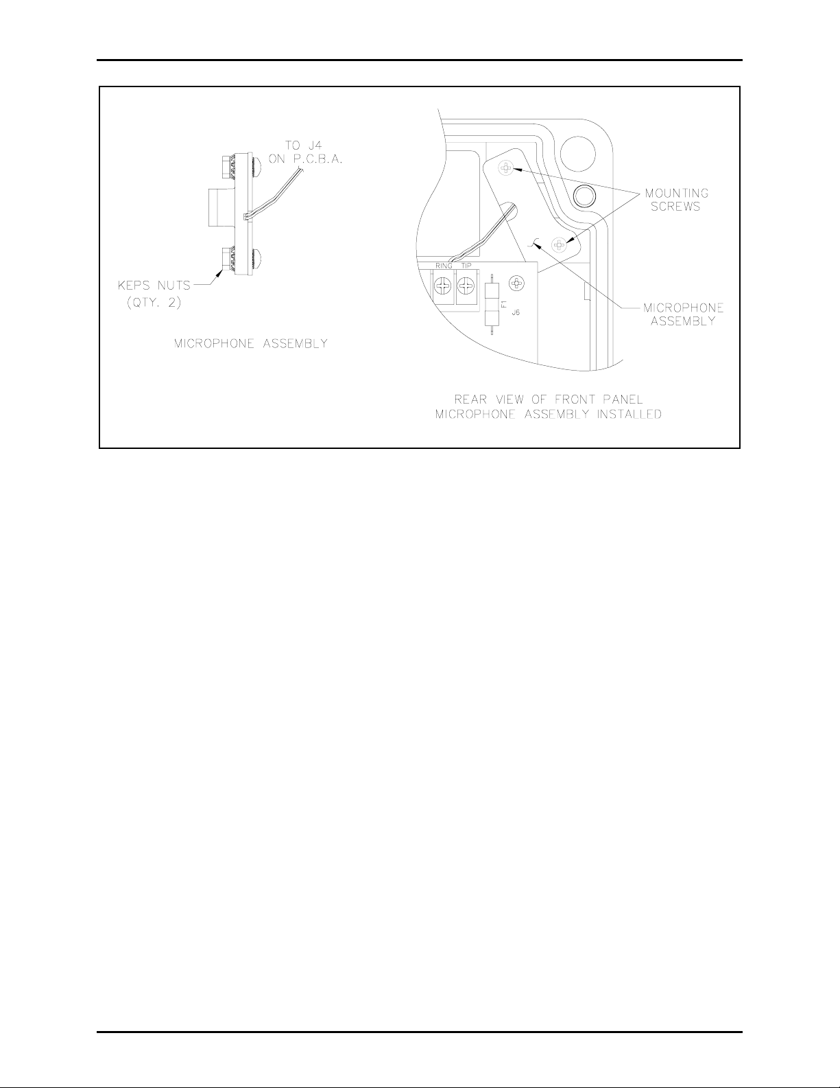
Figure 1. Microphone Assembly
Installing the New Mi crophone Assembly
Refer to Figure 1.
1. Remove the two Keps nuts holding the new microphone assembly together. These nuts are for
shipping purposes only and are not used in the phone. Keep the two Phillips head screws. These will
be used to mount the new microphone assembly to the phone.
2. Position the microphone in the front panel as shown in Figure 1 and use the screws from step one to
mount the microphone in place. Make sure the wires from the microphone are not pinched by the
pressure plate as you tighten the screws.
3. Route the microphone wires under the PCBA and plug the microphone connector into J4.
4. Using the supplied tie wrap re-anchor the speaker, hookswitch, and microphone wires to the tie
anchor.
5. Reconnect all field wiring as noted in step 1 of the “Removing Old Microphone Assembly” section.
6. Place the front onto back box, tighten the tamper-resistant screws, and make a test call from the unit.
OTE: Installation of a new microphone may require the volume level to be readjusted. In this case, see
N
the unit’s original installation manual for adjustment instructions.
09/09
Page 3

Warranty
Equipment. GAI-Tronics warrants for a period of one (1) year from the date of shipment, that any
GAI-Tronics equipment supplied hereunder shall be free of defects in material and workmanship, shall
comply with the then-current product specifications and product literature, and if applicable, shall be fit
for the purpose specified in the agreed-upon quotation or proposal document. If (a) Seller’s goods prove
to be defective in workmanship and/or material under normal and proper usage, or unfit for the purpose
specified and agreed upon, and (b) Buyer’s claim is made within the warranty period set forth above,
Buyer may return such goods to GAI-Tronics’ nearest depot repair facility, freight prepaid, at which time
they will be repaired or replaced, at Seller’s option, without charge to Buyer. Repair or replacement shall
be Buyer’s sole and exclusive remedy. The warranty period on any repaired or replacement equipment
shall be the greater of the ninety (90) day repair warranty or one (1) year from the date the original
equipment was shipped. In no event shall GAI-Tronics warranty obligations with respect to equipment
exceed 100% of the total cost of the equipment supplied hereunder. Buyer may also be entitled to the
manufacturer’s warranty on any third-party goods supplied by GAI-Tronics hereunder. The applicability
of any such third-party warranty will be determined by GAI-Tronics.
Services. Any services GAI-Tronics provides hereunder, whether directly or through subcontractors,
shall be performed in accordance with the standard of care with which such services are normally
provided in the industry. If the services fail to meet the applicable industry standard, GAI-Tronics will
re-perform such services at no cost to buyer to correct said deficiency to Company's satisfaction provided
any and all issues are identified prior to the demobilization of the Contractor’s personnel from the work
site. Re-performance of services shall be Buyer’s sole and exclusive remedy, and in no event shall GAITronics warranty obligations with respect to services exceed 100% of the total cost of the services
provided hereunder.
Warranty Periods. Every claim by Buyer alleging a defect in the goods and/or services provided
hereunder shall be deemed waived unless such claim is made in writing within the applicable warranty
periods as set forth above. Provided, however, that if the defect complained of is latent and not
discoverable within the above warranty periods, every claim arising on account of such latent defect shall
be deemed waived unless it is made in writing within a reasonable time after such latent defect is or
should have been discovered by Buyer.
Limitations / Exclusions. The warranties herein shall not apply to, and GAI-Tronics shall not be
responsible for, any damage to the goods or failure of the services supplied hereunder, to the extent
caused by Buyer’s neglect, failure to follow operational and maintenance procedures provided with the
equipment, or the use of technicians not specifically authorized by GAI-Tronics to maintain or service the
equipment. THE WARRANTIES AND REMEDIES CONTAINED HEREIN ARE IN LIEU OF AND
EXCLUDE ALL OTHER WARRANTIES AND REMEDIES, WHETHER EXPRESS OR IMPLIED BY
OPERATION OF LAW OR OTHERWISE, INCLUDING ANY WARRANTIES OF
MERCHANTABILITY OR FITNESS FOR A PARTICULAR PURPOSE.
Return Policy
If the equipment requires service, contact your Regional Service Center for a return authorization number
(RA#). Equipment should be shipped prepaid to GAI-Tronics with a return authorization number and a
purchase order number. If the equipment is under warranty, repairs or a replacement will be made in
accordance with the warranty policy set forth above. Please include a written explanation of all defects to
assist our technicians in their troubleshooting efforts.
Call 800-492-1212 (inside the USA) or 610-777-1374 (outside the USA) for help identifying the
Regional Service Center closest to you.
(Rev. 10/06)
 Loading...