

Page 1

Pub. 42003-239B
GAI-TRONICS® CORPORATION
A HUBBELL COMPANY
Piezo Switch Assembly R eplacement Kit
for 300 Series Telephones
MODELS 12520-011 AND 12520-012
Confidentiality Notice
This manual is provided solely as an operational, installation, and maintenance guide and contains
sensitive business and technical information that is confidential and proprietary to GAI-Tronics. GAITronics retains all intellectual property and other rights in or to the information contained herein, and
such information may only be used in connection with the operation of your GAI-Tronics product or
system. This manual may not be disclosed in any form, in whole or in part, directly or indirectly, to any
third party.
General Information
The Model 12520-011 (red) and 12520-012 (black) Piezo Switch Assembly Replacement Kits are
intended for use in GAI-Tronics 300 Series Telephones equipped with the cold weather option (-003 and
-004).
The Model 12520-011 is for use on the Model 393, 393AL, 394AL, 396, 397, and 398 Series
Telephones. The Model 12520-012 is for use on the Model 394AL, 396, and 398 Series Telephones.
The replacement procedures are the same for both kits.
Kit Components
Qty. Description Required Tools
1 Piezo Switch Assembly
1 O-Ring
1 Tie Wrap
#1 Phillips screwdriver
1-1/4-inch box wrench
Model 233-001 Security Screwdriver
Wire cutters
Model 393, 393AL, and 394AL Series T elephones
Removing the Old Piezo Switch Assembl y
1. Use a Model 233-001 Security Screwdriver to loosen the four front cover screws. Save the screws
for re-assembly.
2. Lift the front cover assembly away from the back box.
3. Disconnect the telephone line cord and strobe wires, if applicable.
GAI-Tronics Corporation 400 E. Wyomissing Ave. Mohnton, PA 19540 USA
610-777-1374 800-492-1212 Fax: 610-796-5954
ISIT WWW.GAI-TRONICS.COM FOR PRODUCT LITERATURE AND MANUALS
V
Page 2
Pub. 42003-239B
M
ODELS 12520-011 AND 12520-012 PIEZO SWITCH ASSEMBLY REPLACEMENT KIT Page 2 of 3
4. Place the front cover assembly
face down on a flat surface.
5. Use the wire cutters to snip the tie
wrap that is securing the pushbutton assembly cable to the other
wires.
6. Unplug the piezo switch cable
assembly connector from the
PCBA. Be sure to note the
location of the connection for reassembly.
7. Remove #4-40 screws securing
PCBA to standoffs using #1
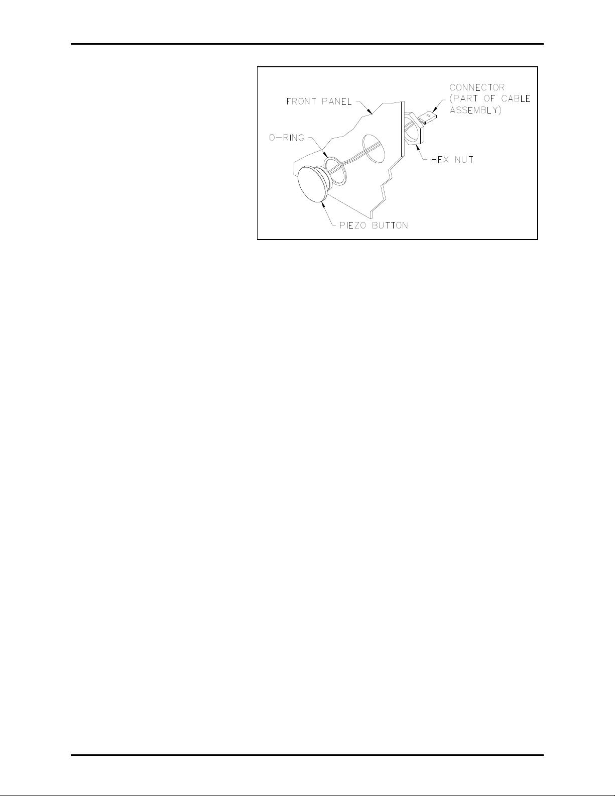
Figure 1. Piezo Push-Button Switch Assembly, Exploded View
Phillips screwdriver. Pull PCBA
away.
8. Using the 1-1/4 inch box wrench, loosen the hex nut. See Figure 1 for location.
9. Remove and discard the hex nut and piezo switch assembly. Remove any residual gasket material
from the front cover.
Installing the New Piezo Sw itch Assembly
1. Slide the O-ring over the piezo switch threads to the undercut location.
2. From the front side of the panel, push the new push-button assembly through the hole. See Figure 1.
3. Secure the piezo switch assembly to the front cover using the hex nut. See Figure 1.
4. Use the enclosed tie wrap to secure the push-button assembly cable to the other wires, and attach to
the anchor.
5. Replace the #4-40 screws that secure the PCBA to the standoffs.
6. Plug the push-button assembly cable into the PCBA at the proper location noted earlier.
7. Reconnect the telephone line cord, and strobe wires, if applicable.
8. Align the front cover with the rear enclosure, and use the Model 233-001 Security Screwdriver to
secure four front cover screws (previously saved).
f:\standard ioms - current release\42003 kit manuals\42003-239b.doc
08/12
Page 3

Pub. 42003-239B
M
ODELS 12520-011 AND 12520-012 PIEZO SWITCH ASSEMBLY REPLACEMENT KIT Page 3 of 3
Model 396, 397 and 398 Series T elephones
Removing the Old Piezo Switch Assembl y
1. Use a Model 233-001 Security Screwdriver to remove the six front panel screws. Save the screws for
re-assembly.
2. Lift the front panel assembly away from the back box approximately 6 to 8 inches.
3. Unplug the telephone line cord from the modular block in the back box, and disconnect the strobe
wires, if applicable.
4. Remove the front panel assembly, and place it face down on a flat surface.
5. Use the wire cutters to snip the tie wrap that is securing the push-button assembly cables to the other
wires.
6. Unplug the piezo switch assembly cable from the PCBA. Be sure to note the location of the
connection for re-assembly.
10. Using the 1-1/4 inch box wrench, loosen the hex nut. See Figure 1.
11. Remove and discard the hex nut and piezo switch assembly. Remove any residual gasket material
from the front cover.
Installing the New Piezo Sw itch Assembly
1. Slide the O-ring over the piezo switch threads to the undercut location.
2. From the front side of the panel, push the new push-button assembly through the hole. See Figure 1.
3. Plug the piezo switch assembly cable into the PCBA at the proper location.
4. Use the enclosed tie wrap to secure the piezo switch assembly cable to the other wires.
5. Plug the telephone line cord into the modular block in the back box, and reconnect the strobe wires,
if applicable.
6. Align the front cover with the rear enclosure, and use the Model 233-001 Security Screwdriver to
secure six front panel screws (previously saved).
f:\standard ioms - current release\42003 kit manuals\42003-239b.doc
08/12
Page 4

Warranty
Equipment. GAI-Tronics warrants for a period of one (1) year from the date of shipment, that any
GAI-Tronics equipment supplied hereunder shall be free of defects in material and workmanship, shall
comply with the then-current product specifications and product literature, and if applicable, shall be fit
for the purpose specified in the agreed upon quotation or proposal document. If (a) Seller’s goods prove
to be defective in workmanship and/or material under normal and proper usage, or unfit for the purpose
specified and agreed upon, and (b) Buyer’s claim is made within the warranty period set forth above,
Buyer may return such goods to GAI-Tronics nearest depot repair facility, freight prepaid, at which time
they will be repaired or replaced, at Seller’s option, without charge to Buyer. Repair or replacement shall
be Buyer’s sole and exclusive remedy. The warranty period on any repaired or replacement equipment
shall be the greater of the ninety (90) day repair warranty or one (1) year from the date the original
equipment was shipped. In no event shall GAI-Tronics warranty obligations with respect to equipment
exceed 100% of the total cost of the equipment supplied hereunder. Buyer may also be entitled to the
manufacturer’s warranty on any third-party goods supplied by GAI-Tronics hereunder. The applicability
of any such third-party warranty will be determined by GAI-Tronics.
Services. Any services GAI-Tronics provides hereunder, whether directly or through subcontractors,
shall be performed in accordance with the standard of care with which such services are normally
provided in the industry. If the services fail to meet the applicable industry standard, GAI-Tronics will reperform such services at no cost to buyer to correct said deficiency to Company's satisfaction provided
any and all issues are identified prior to the demobilization of the Contractor's personnel from the work
site. Re-performance of services shall be Buyer's sole and exclusive remedy, and in no event shall GAITronics warranty obligations with respect to services exceed 100% of the total cost of the services
provided hereunder.
Warranty Periods. Every claim by Buyer alleging a defect in the goods and/or services provided
hereunder shall be deemed waived unless such claim is made in writing within the applicable warranty
periods as set forth above. Provided, however, that if the defect complained of is latent and not
discoverable within the above warranty periods, every claim arising on account of such latent defect shall
be deemed waived unless it is made in writing within a reasonable time after such latent defect is or
should have been discovered by Buyer.
Limitations / Exclusions. The warranties herein shall not apply to, and GAI-Tronics shall not be
responsible for, any damage to the goods or failure of the services supplied hereunder, to the extent
caused by Buyer’s neglect, failure to follow operational and maintenance procedures provided with the
equipment, or the use of technicians not specifically authorized by GAI-Tronics to maintain or service the
equipment. THE WARRANTIES AND REMEDIES CONTAINED HEREIN ARE IN LIEU OF AND
EXCLUDE ALL OTHER WARRANTIES AND REMEDIES, WHETHER EXPRESS OR IMPLIED BY
OPERATION OF LAW OR OTHERWISE, INCLUDING ANY WARRANTIES OF
MERCHANTABILITY OR FITNESS FOR A PARTICULAR PURPOSE.
Return Policy
If the equipment requires service, contact your Regional Service Center for a return authorization number
(RA#). Equipment should be shipped prepaid to GAI-Tronics with a return authorization number and a
purchase order number. If the equipment is under warranty, repairs or a replacement will be made in
accordance with the warranty policy set forth above. Please include a written explanation of all defects to
assist our technicians in their troubleshooting efforts.
Call 800-492-1212 (inside the USA) or 610-777-1374 (outside the USA) for help identifying the
Regional Service Center closest to you.
(Rev. 10/06)
 Loading...