

Page 1

Pub. 42003-173
GAI-TRONICS® CORPORATION
A HUBBELL COMPANY
Round Push-Button As sembly
Replacement Kit
MODELS 12520-006 AND 12520-007
Confidentiality Notice
This manual is pr ovided s olely as a n op erat ional, installation, and maintenance guide and contains sens itive
bus ines s and t echnic al infor ma tion tha t is confident i al and p roprietary to G AI-Tronics. GAI-Tronics
retains a ll intellectual pr operty and other rights in or to t he inf ormation c ontained herein, and s uch
informa tion may only be used in connection wit h the operation of you r GAI- Tronic s pr oduct or system.
This ma nual may not be disclosed in any form, in whole or in p art, dir ec tly or indirectly, to any t hird pa rty.
General Information
The Model 12520-006 is a 1.5-inch red push-button assembly kit used on the Model 293, 293AL, 294AL,
297, and 298 Telephones. The Model 12520-007 is a 1-inch black push-button assembly kit used on the
Model 294AL and 298 Telephones. The installa tion procedures are t he s ame for both kits.
Kit Components
Qty. Description Required Tools
1 Push-button Switch Assembly
1 Mounting Nut
1 Mounting Ring
1 Tie Wrap
• #2 P hillip s Screwdriver
• 1/8-inch Straight Slot Screwdriver
• Model 233 Tamper-Resistant Screwdriver
• Wire Cutters
Model 293, 293AL, and 294AL T elephones
Removing the Old Push-Button Assembly
1. Use a Model 233 Tamper-Resistant Screwdriver to loosen the four front cover screws. Save the
screws for re-assembly.
2. For Model 293AL and 294AL: Lift the front cover as sembly awa y f rom the ba c k box.
For Model 293: Open the front c over as sembly of the unit by swinging the cover to the left.
3. Disconnect the telephone line cor d.
GAI-Tronics Corporation P.O. Box 1060, Reading, PA 19607-1060 USA
610-777-1374 800-492-1212 Fax : 610-796-5954
ISIT WWW.GAI-TRONICS.COM FOR PRODUCT LITERATURE AND MANUALS
V
Page 2
Pub. 42003-173
M
ODELS 12520-006 AND 12520-007 ROUND PUSH-BUTTON ASSEMBLY REPLACEMENT KIT Page: 2 of 3
4. Use the wire cutters to snip the tie
wra p that is secur ing the pushbut ton as sembly cable to the ot her
wires.
5. Unplug the push-button assembly
cab l e connector f rom the PCBA.
Be sure to note t he location of the
connection for re-ass embly.
6. For Model 293AL and 294AL:
Pla c e the front c over assembly
fac e down on a fla t surface.
For Model 293: Pull the front
cover assembly s traight out and
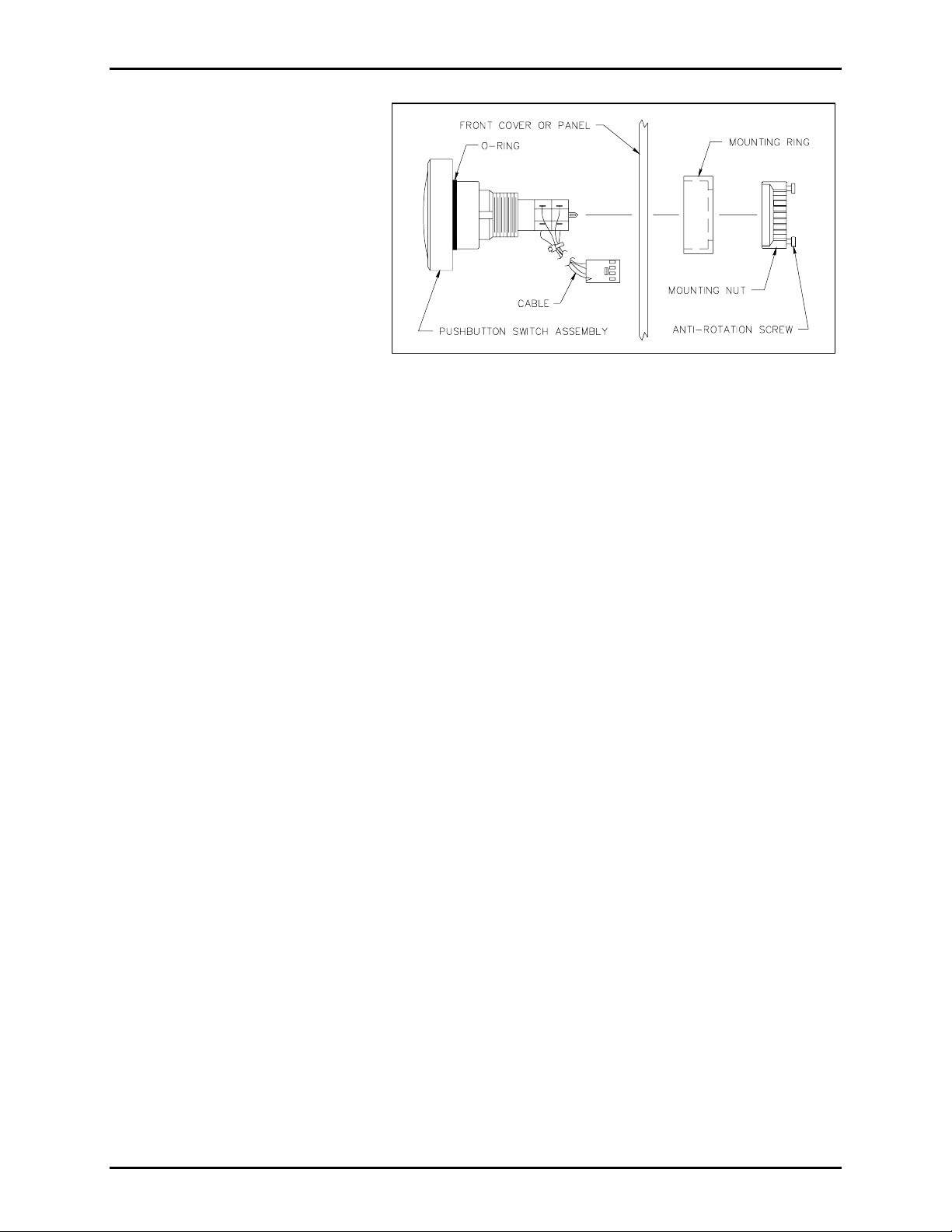
Figure 1. Push-Button Switch Assembly,
Exp loded View
away from the back box. Place
the fr ont cover ass embly f ace down on a f l at s urface.
7. Using the 1 /8-inch straight slot s c rewdriver, loos en t he anti-rotation s c rews on t he mounting nut.
See Figu re 1.
8. Remove and disc ard the pus h- button as sembly, t he mounting nut, and the mounting r ing.
Installing the New Push-Button Assembly
1. Fr om t he front side of the panel, push the new p ush-butt on ass embly through the hole. See F i gure 1.
2. Secure the pu sh-bu tton assembly to the fr ont cover using the mounting ring and the mounting nut. See
Figure 1.
OTE: Ensure t hat the o-ring s eal is in its pr oper location, as s hown in Figure 1.
N
3. Tighten the anti-r otat ion screws on the mounting nut.
4. Model 293 only: Align the hinge plugs with the rea r enclosu re and p ush firmly into place.
5. Plug th e push-but ton assembly cable into th e PC B A at the p rop er location no ted ea rli er.
6. Use t h e enclos ed tie wrap to secu re th e push-b utton a ssemb ly cable to the o ther wires.
7. Reconnect the telephone line cord.
8. Model 293 only: Swing the front cover cl osed.
9. Align the front cover with the rear enclosure, and use the Model 233 Tamper-Resistant Screwdriver to
secure four fr ont cover screws (previously saved).
\\s_eng\gtc proddoc s \ s tandard ioms - current release\ 42003 k it m anuals \42003-173.doc
11/98
Page 3

Pub. 42003-173
M
ODELS 12520-006 AND 12520-007 ROUND PUSH-BUTTON ASSEMBLY REPLACEMENT KIT Page: 3 of 3
Models 297 and 298
Removing the Old Push-Button Assembly
1. Use a Model 233 Tamper-Resistant Screwdriver to remove the six front panel screws. Save the screws
for re-assembly.
2. Lift the front panel assembly away from the back box approximately 6 to 8 inches.
3. Unplug t he telephone line cord from the modular block in the back box .
4. Remove the front pa nel assembly, and p lace it f ace down on a f lat s urface.
5. Use the #2 Phillips screwdr iver to r emove the four screws securing the shield over the PCBA. Sa ve t he
screws for re-assembly.
6. Use the wire cutters to snip the tie wrap that is securing the push-button assembly cables to the other
wires.
7. Unplug the push-button a ssembly ca ble from t he PCBA. Be sur e t o note the loca tion of the connection
for re-assembly.
8. Using the 1 /8-inch straight slot s c rewdriver, loos en t he anti-rotation s c rews on t he mounting nut.
9. Remove and disc ard the pus h- button as sembly, t he mounting nut and the mount ing ring.
Installing the New Push-Button Assembly
1. Fr om t he front side of the panel, push the new p ush-butt on ass embly through the hole. See F i gure 1.
2. Secure the pu sh-bu tton a ssembly to the panel u sing the mounting ring, and the mount ing nut.
See Figu re 1.
OTE: Ensure t hat the O-ring seal is in its proper loc ation, as shown in Figu re 1.
N
3. Tighten the anti-r otat ion screws on the mounting nut.
4. Plug th e push-but ton assembly cable into th e PC B A at the p rop er location no ted ea rli er.
5. Use t h e enclos ed tie wrap to secu re th e push-b utton a ssemb ly cable to the o ther wires.
6. Pla c e t he shield over the PCBA a nd use the #2 Phillips s c rewdriver to secure the four screws
(previously s aved).
7. Plug the telephone line cord int o the modular block in the back box .
8. Align the front cover with the rear enclosure, and use the Model 233 Tamper-Resistant Screwdriver to
secure six f ront p anel screws (p reviousl y saved).
\\s_eng\gtc proddoc s \ s tandard ioms - current release\ 42003 k it m anuals \42003-173.doc
11/98
Page 4

Warranty
Equipment. GAI-Tronics warrants for a period of one (1) year from the date of shipment, that any
GAI-Tronics equipment supplied hereunder shall be free of defects in material and workmanship, shall
comply with the then-current product specifications and product literature, and if applicable, shall be fit
for the purpose specified in the agreed-upon quotation or proposal document. If (a) Seller’s goods prove
to be defective in workmanship and/or material under normal and proper usage, or unfit for the purpose
specified and agreed upon, and (b) Buyer’s claim is made within the warranty period set forth above,
Buyer may return such goods to GAI-Tronics’ nearest depot repair facility, freight prepaid, at which time
they will be repaired or replaced, at Seller’s option, without charge to Buyer. Repair or replacement shall
be Buyer’s sole and exclusive remedy. The warranty period on any repaired or replacement equipment
shall be the greater of the ninety (90) day repair warranty or one (1) year from the date the original
equipment was shipped. In no event shall GAI-Tronics warranty obligations with respect to equipment
exceed 100% of the total cost of the equipment supplied hereunder. Buyer may also be entitled to the
manufacturer’s warranty on any third-party goods supplied by GAI-Tronics hereunder. The applicability
of any such third-party warranty will be determined by GAI-Tronics.
Services. Any services GAI-Tronics provides hereunder, whether directly or through subcontractors,
shall be performed in accordance with the standard of care with which such services are normally
provided in the industry. If the services fail to meet the applicable industry standard, GAI-Tronics will
re-perform such services at no cost to buyer to correct said deficiency to Company's satisfaction provided
any and all issues are identified prior to the demobilization of the Contractor’s personnel from the work
site. Re-performance of services shall be Buyer’s sole and exclusive remedy, and in no event shall GAITronics warranty obligations with respect to services exceed 100% of the total cost of the services
provided hereunder.
Warranty Periods. Every claim by Buyer alleging a defect in the goods and/or services provided
hereunder shall be deemed waived unless such claim is made in writing within the applicable warranty
periods as set forth above. Provided, however, that if the defect complained of is latent and not
discoverable within the above warranty periods, every claim arising on account of such latent defect shall
be deemed waived unless it is made in writing within a reasonable time after such latent defect is or
should have been discovered by Buyer.
Limitations / Exclusions. The warranties herein shall not apply to, and GAI-Tronics shall not be
responsible for, any damage to the goods or failure of the services supplied hereunder, to the extent
caused by Buyer’s neglect, failure to follow operational and maintenance procedures provided with the
equipment, or the use of technicians not specifically authorized by GAI-Tronics to maintain or service the
equipment. THE WARRANTIES AND REMEDIES CONTAINED HEREIN ARE IN LIEU OF AND
EXCLUDE ALL OTHER WARRANTIES AND REMEDIES, WHETHER EXPRESS OR IMPLIED BY
OPERATION OF LAW OR OTHERWISE, INCLUDING ANY WARRANTIES OF
MERCHANTABILITY OR FITNESS FOR A PARTICULAR PURPOSE.
Return Policy
If the equipment requires service, contact your Regional Service Center for a return authorization number
(RA#). Equipment should be shipped prepaid to GAI-Tronics with a return authorization number and a
purchase order number. If the equipment is under warranty, repairs or a replacement will be made in
accordance with the warranty policy set forth above. Please include a written explanation of all defects to
assist our technicians in their troubleshooting efforts.
Call 800-492-1212 (inside the USA) or 610-777-1374 (outside the USA) for help identifying the
Regional Service Center closest to you.
(Rev. 10/06)
 Loading...