

Page 1

Pub. 42003-035B
GAI-TRONICS® CORPORATION
A HUBBELL COMPANY
PVC Coil Cord Replacement Kit
Models 12514-007, 12514-008, and 12514-009
Confidentiality Notice
This manua l is provide d sole ly as an operatio nal, installation, and ma inte nance guide and conta ins
sensitive business and t e chnic al infor ma tion w hich is conf ident ial and pr op riet ary to GAI-Tro nics.
GAI-Tronics retains all intellectual property and other rights in or to the information contained herein,
and such information may only be used in connection with the operation of your GAI-Tronics product or
system. This manu al may not be dis clos e d in any form, in whole or in pa rt, direct ly or i ndir ectly, to a ny
third pa r ty.
General Information
These kits are for use on the following models:
• 240 • 250 • 611 • 701-201 • 701-205 • 7165-002
• 246 • 256 • 6115 • 701-202 • 711-002 • 726-101
• 247 • 257 • 616 • 701-203 • 7115-002 • 7265-101
• 248 • 258 • 6165 • 701-204 • 716-002
This kit includes the following components:
Qty Description
1 Strain-relief Bushing
1 6-foot PVC cord (Kit 12514-007 only)
1 15-foot PVC cord (Kit 12514-008 only)
1 25-foot PVC cord (Kit 12514-009 only)
Installation
Models 240, 246, 247, 248, 250, 256, 25 7, 258
Removal of old cord
1. Loosen and remove the screws securing the front panel. Pull the front panel assembly away from the
back enclosure.
2. Disconnect the modular telephone line from the PC board. Disconnect the four handset wires from
the PC board.
3. When replacing a PVC cord, use a Heyco® bushing tool, or a set of needlenose pliers, to squeeze the
notch on the front panel side of the strain relief bushing and pull out the bushing.
GAI-Tronics Corporation P.O. Box 1060, Readi ng, PA 19607-1060 USA
610-777-1374 800-492-1212 Fax: 610-796-5954
ISIT WWW.GAI-TRONICS.COM FOR PRODUCT LITERATURE AND MANUALS
V
Page 2
Pub. 42003-035B
M
ODELS 12514-007, 12514-008, AND 12514-009 PVC COIL CORD REPLACEMENT KIT Page: 2 of 6
4. When replacing a thermoplastic elastomer cord, remove the C-clip securing the bushing and the cord
to the rear of the front panel assembly.
5. Pull the old cord through the fr ont panel assembly.
6. Remove the lower cap from the handset. Lift out the transmitter and disconnect both wires.
7. Remove the receiver cap, lift out the receiver and disconnect both wires.
8. Pull the wire ha rness out of the ha ndset and discard the c ord.
Installatio n of the ne w cord
1. Insert the wire harnes s from t he n ew cord int o the handset.
2. Snip off the blue and yellow wires as close to their origin as possible. Connect the red and green
wires to the receiver. Replace the receiver and the receiver cap.
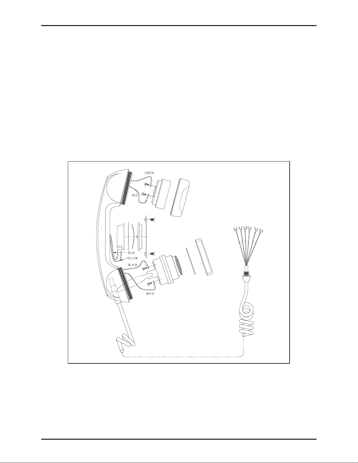
Figure 1. Handset As semb ly with Pressb ar
3. Connect the black and white wires to the transmitter. Replace the transmitter, transmitter cup, and
cap. Refer to Figure 1. Note the notch on the transmitter. When placing the transmitter in the
handset, align the notch to catch the bushing on the coil cord to secure the cord firmly in the handset.
4. Insert the end of the new cord through the front panel assembly until the bushing is flush against the
panel.
\\s_eng\gtc proddoc s \st andard iom s - current release\42003 kit manuals \ 42003-035b.doc
Page 3

Pub. 42003-035B
M
ODELS 12514-007, 12514-008, AND 12514-009 PVC COIL CORD REPLACEMENT KIT Page: 3 of 6
5. Press the bushing tight against the front panel, and insert the C-clip on the rear of the bushing on the
back side of the front panel assembly, or use a Heyco® bushing tool to squeeze the Heyco® bushing
back into the front panel opening.
6. Reconnect the four telephone wires to the PC board in this manner: red to E1; green to E2; white to
E3; black to E4.
7. Reconnect the modular telephone wire to the RJ11 jack on the PC board and fasten the front panel
assembly to the rear enclosure.
Models 701-201, 701-202, 701-203, 701- 204, and 701-205
Removal of old cord
1. Unscrew the four front panel screws and remove the handset amplifier from the enclosure.
2. Unscrew the handset transmitter cap and lift out the transmitter.
3. Disconnect the wires from the transmitter.
4. Unscrew the receiver cap. Lift out the receiver.
5. Disconnect the red and green wires from the handset PC board. For stations with a pressbar handset,
proceed t o Step 6. For sta tions without a pressbar hands et , procee d to St ep 8.
6. Loosen the tw o scr ews s ecu ring the pressbar. Lift off the metal r eta iner, plastic pressbar, cur ved
spring and plunger.
7. Lift out the rectangular plastic cup and disconnect the blue and yellow wires.
8. Pull the old cord out of the handset. Place the amplifier to easily access the rear of the unit.
9. Loosen the four screws securing the backbox to the amplifier. The backbox will still be connected to
the amplifier. Carefully separate a the two pieces.
10. Disconnect the yellow (E5), blue (E6), red (E4), white (E1), black (E2) and green (E3) wires from the
PC boar d. Stations wi thout pressbar hands ets wi ll not have the blue and yel low wires.
11. Using a Heyco® bushing tool or needlenose pliers, pull the bushing and the cord through the front
panel and discard.
\\s_eng\gtc proddoc s \st andard iom s - current release\42003 kit manuals \ 42003-035b.doc
Page 4

Pub. 42003-035B
M
ODELS 12514-007, 12514-008, AND 12514-009 PVC COIL CORD REPLACEMENT KIT Page: 4 of 6
Installatio n of new co rd
1. Feed the red and green wires through the transmitter end of the handset, through the center of the
handset receiv er end. Place the b ra ss eyel ets on the receiver as i n dicated i n Figur e 2. Feed the screws
through the handset PCBA through the eyelet and into the receiver. Secure the wires as indicated in
Figure 2.
2. Place the receiver in the cup. Tighten the
receiver cap. For stations with a pressbar
handset, proceed t o Stop 3. For stations
without a pressba r han ds et, p roceed to
Step 8.
3. Feed the yellow and blue wires through
the handset to the pressbar area.
4. Secure the wires to the terminals in the
plastic cup. Place the plastic cup in the
handset.
5. Se e Fig ure 1 a bove. P l ace the copper
piece with the rubber center in first, with
the solid rubber side facing up and the
Figure 2. Receiver Detail for 701 Models
notch in the appropriate slot.
6. Place the o th er co pp er p iece so tha t th e bend fac es out.
7. Place the plastic piece such that the GTC logo side is facing up. Place the metal bracket on top and
tighten the screws.
8. FOR HANDSETS WITHOUT A PRESSBAR ONLY: Snip off the blue and yellow wires as close to
their origin as possible.
9. Attach the wires to the transmitter terminals.
10. Place the transmitter in the transmitter cap, making sure that the cord guide snaps firmly onto the cord
to secure it. Screw on the transmitter cap.
11. Feed the end of the cord through from the front panel of the phone and use the Heyco® bushing tool
or needlenose pliers to secure the bushing on the amplifier front.
12. Connect the wires to the PC board: red to E4, white to E1, black to E2, yellow to E5, blue to E6 and
green to E 3. Stations without pressba r handsets wil l not have t he blu e and ye llo w wir es .
13. Secure the backbox by tightening the four screws.
14. Reinstall the amplifier into the enclosure.
\\s_eng\gtc proddoc s \st andard iom s - current release\42003 kit manuals \ 42003-035b.doc
Page 5

Pub. 42003-035B
M
ODELS 12514-007, 12514-008, AND 12514-009 PVC COIL CORD REPLACEMENT KIT Page: 5 of 6
Models 711-002, 7115-002, 611C, and 6115
Removal of old cord
1. Remove the two mounting screws from the mounting bracket. Remove the subset from the mounting
bracket.
2. Remove the four screws on the left side of the unit.
3. Locate the PC board. On the side closest to you, you will see the six handset wires. Unplug all six of
the wires.
4. Use a Heyco® bushing tool to remove the bushing securing the cord to the subset. Pull the cord
through the hole and remove.
5. At the handset end, unscrew the transmitter cap, lift out the transmitter and disconnect the wires.
6. Unscrew the receiver cap, lift out the receiver and disconnect the red and green wires from the
receiver.
7. FOR HANDSETS WITH PRESSBAR ONLY: Loosen the two screws securing the pressbar. Lift off
the metal retainer, plastic pressbar, curved spring and plunger. Lift out the rectangular plastic cup and
disconnect the blue and yellow wires.
8. Pull the ol d cord out of the ha ndset and disca rd.
Installatio n of new co rd
1. Feed the red and green wires through the transmitter end of the handset, through the center of the
handset to the receiver end. Secure the wires to the receiver.
2. Place the receiver in the cup. Tighten the receiver cap.
3. FOR HANDSETS WITH PRESSBAR ONLY: Feed the yellow and blue wires through the handset
to the pressbar area. Secure the wires to the terminals in the plastic cup. Place the plastic cup in the
handset. Refer to Figure 1. Place the copper piece with the rubber center in first, with the solid
rubber side up. Install the curved spring. Place the plastic pressbar in with the GTC logo side up.
Place the metal bracket on top. Tighten the screws.
4. Attach the black and white wires to the transmitter terminals.
5. Place the transmitter in the transmitter cup, making sure that the cord guide snaps firmly onto the cord
to secure it. Screw on the transmitter cap.
6. Feed the other end of the cord through from the front panel of the phone and use a Heyco® tool or
needlenose pliers to secure the bushing on the front of the subset.
7. Reconnect the wires to the PC board according to the labels on the board.
8. Replace the four screws to reassemble the unit.
9. Use the two mounting screws to secure the subset to the mounting bracket.
\\s_eng\gtc proddoc s \st andard iom s - current release\42003 kit manuals \ 42003-035b.doc
Page 6

Pub. 42003-035B
M
ODELS 12514-007, 12514-008, AND 12514-009 PVC COIL CORD REPLACEMENT KIT Page: 6 of 6
Models 616C, 6165, 716-002, and 7165-002
Removal of old cord
1. Remove the unit from the wall or mounting surface.
2. Remove the four back panel screws.
3. Follow Steps 3 through 7 under “Removal of old cord” in the section for 611C, 6115, 711-002, and
7115-002 above.
Installatio n of new co rd
1. Follow Steps 1 through 7 under “Installation of new cord” in the section for 611C, 6115, 711-002,
and 7115-002 above.
2. Replace the four back panel screws.
3. Remount the unit.
Models 726 and 7265-101
Removal of old cord
1. Loosen the four screws securing the housing to the base.
2. Hinge the housing forward to access the inside of the subset.
3. Follow Steps 3 through 7 under “Removal of old cord” in the section for 611C, 6115, 711-002, and
7115-002 above.
Installatio n of new co rd
1. Follow Steps 1 through 7 under “Installation of new cord” in the section for 611C, 6115, 711-002,
and 7115-002 above.
2. Place the housing on the base and tighten the four screws.
\\s_eng\gtc proddoc s \st andard iom s - current release\42003 kit manuals \ 42003-035b.doc
Page 7

Warranty
Equipment. GAI-Tronics warrants for a period of one (1) year from the date of shipment, that any
GAI-Tronics equipment supplied hereunder shall be free of defects in material and workmanship, shall
comply with the then-current product specifications and product literature, and if applicable, shall be fit
for the purpose specified in the agreed-upon quotation or proposal document. If (a) Seller’s goods prove
to be defective in workmanship and/or material under normal and proper usage, or unfit for the purpose
specified and agreed upon, and (b) Buyer’s claim is made within the warranty period set forth above,
Buyer may return such goods to GAI-Tronics’ nearest depot repair facility, freight prepaid, at which time
they will be repaired or replaced, at Seller’s option, without charge to Buyer. Repair or replacement shall
be Buyer’s sole and exclusive remedy. The warranty period on any repaired or replacement equipment
shall be the greater of the ninety (90) day repair warranty or one (1) year from the date the original
equipment was shipped. In no event shall GAI-Tronics warranty obligations with respect to equipment
exceed 100% of the total cost of the equipment supplied hereunder. Buyer may also be entitled to the
manufacturer’s warranty on any third-party goods supplied by GAI-Tronics hereunder. The applicability
of any such third-party warranty will be determined by GAI-Tronics.
Services. Any services GAI-Tronics provides hereunder, whether directly or through subcontractors,
shall be performed in accordance with the standard of care with which such services are normally
provided in the industry. If the services fail to meet the applicable industry standard, GAI-Tronics will
re-perform such services at no cost to buyer to correct said deficiency to Company's satisfaction provided
any and all issues are identified prior to the demobilization of the Contractor’s personnel from the work
site. Re-performance of services shall be Buyer’s sole and exclusive remedy, and in no event shall GAITronics warranty obligations with respect to services exceed 100% of the total cost of the services
provided hereunder.
Warranty Periods. Every claim by Buyer alleging a defect in the goods and/or services provided
hereunder shall be deemed waived unless such claim is made in writing within the applicable warranty
periods as set forth above. Provided, however, that if the defect complained of is latent and not
discoverable within the above warranty periods, every claim arising on account of such latent defect shall
be deemed waived unless it is made in writing within a reasonable time after such latent defect is or
should have been discovered by Buyer.
Limitations / Exclusions. The warranties herein shall not apply to, and GAI-Tronics shall not be
responsible for, any damage to the goods or failure of the services supplied hereunder, to the extent
caused by Buyer’s neglect, failure to follow operational and maintenance procedures provided with the
equipment, or the use of technicians not specifically authorized by GAI-Tronics to maintain or service the
equipment. THE WARRANTIES AND REMEDIES CONTAINED HEREIN ARE IN LIEU OF AND
EXCLUDE ALL OTHER WARRANTIES AND REMEDIES, WHETHER EXPRESS OR IMPLIED BY
OPERATION OF LAW OR OTHERWISE, INCLUDING ANY WARRANTIES OF
MERCHANTABILITY OR FITNESS FOR A PARTICULAR PURPOSE.
Return Policy
If the equipment requires service, contact your Regional Service Center for a return authorization number
(RA#). Equipment should be shipped prepaid to GAI-Tronics with a return authorization number and a
purchase order number. If the equipment is under warranty, repairs or a replacement will be made in
accordance with the warranty policy set forth above. Please include a written explanation of all defects to
assist our technicians in their troubleshooting efforts.
Call 800-492-1212 (inside the USA) or 610-777-1374 (outside the USA) for help identifying the
Regional Service Center closest to you.
(Rev. 10/06)
 Loading...