

Page 1
Pub. 42003- 026C
GAI-TRONICS® CORPORATION
A HUBBELL COMPANY
Thermoplastic El as tomer Cord
Replacement Kit
MODELS 12514-004, 12514-005, AND 12514-006
Confidentiality Notice
This manual is pr ovided s olely as a n op erat ional, installation, and maintenance guide and contains sens itive
bus ines s and t echnic al infor ma tion which is conf idential and propriet ary to GAI-Tronics. GAI - Tronic s
retains a ll intellectual pr operty and other rights in or to t he inf ormation c ontained herein, and s uch
informa tion may only be used in connection wit h the operation of you r GAI- Tronic s pr oduct or system.
This ma nual may not be disclosed in any form, in whole or in p art, dir ec tly or indirectly, to any t hird pa rty.
General Information
The cord replacement kits c an be us ed on t he following models:
240 248 257 272 701-804 9081 9105A
246 250 258 701-602 9001 9085 9205A
247 256 262 701-802 9005 9101A 12576-215
This kit includes the following parts:
Qty Description
1 Ha n d set Cord Fastener Clip
2 Tie Wraps
1 6-foot Retractile Thermoplastic Elastomer Cord (Kit 12514-004 Only)
1 15-foot Retractile Thermoplastic Elastomer Cord (Kit 12514-005 Only)
1 25-foot Retractile Thermoplastic Elastomer Cord (Kit 12514-006 Only)
Installation Instructions
Models 240, 246, 247, 248, 250, 256, 257, and 258
Removal of Old Cord
1. Loosen a nd remove the scr ews secur i ng the front panel. Pull the front pa nel away from the ba c k
enclosure.
2. Disconnect the modular telephone line from the printed circ uit board. Disc onnect the 4 telephone wires
from the printed circuit board assembly (PCBA).
GAI-Tronics Corporation P.O. Box 1060, Reading, PA 19607-1060 USA
610-777-1374 800-492-1212 Fax : 610-796-5954
ISIT WWW.GAI-TRONICS.COM FOR PRODUCT LITERATURE AND MANUALS
V
Page 2
Pub. 42003-026C
T
HERMOPLASTIC ELASTOMER CORD REPLACEMENT KIT Page: 2 of 11
3. When replacing an ex isting P VC cord, use a Heyco® bus hing tool or a needle nose pliers t o squeeze the
notch on t he front p anel side of the s train relief bushing a nd pull out the bus hing.
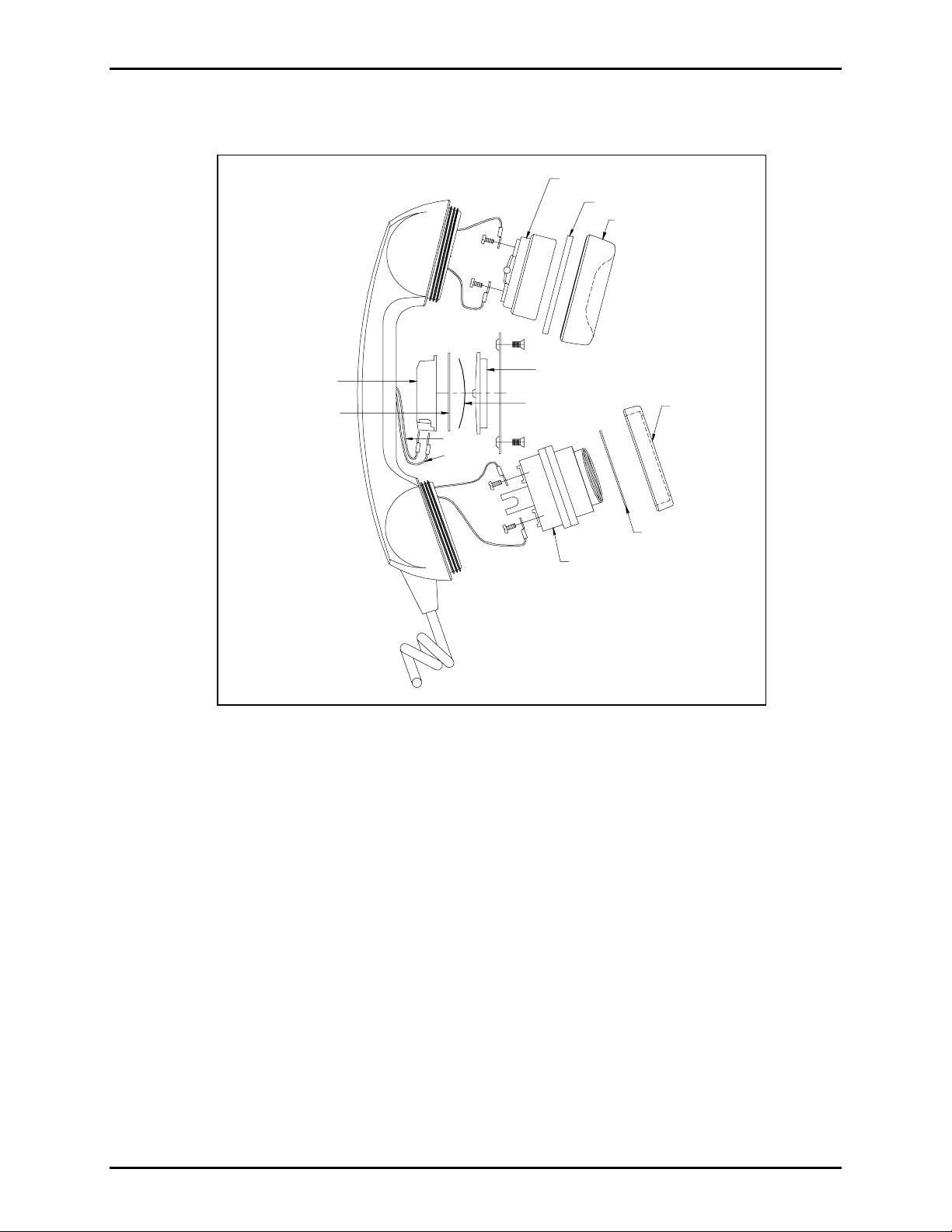
RECEIVER
GREEN
RED
GASKET
RECEIVER
CAP
COPPER SPRING
WHITE
PRESSBAR
TRANSMITTER
TRANSMITTER
CAP
WASHER
PLASTIC CUP
COPPER PLUNGER
BLUE
YELLOW
BLACK
Figure 1. Handset Outline Diagram
4. When replacing a thermoplastic elastomer c ord, remove the handset cord fastener clip located on the
bac k side of the front panel. The fastener clip secur es the bus hing and the cord to the front p anel.
5. Pull the old cord through t he front p anel and s et aside.
6. Remove the lower cap from the handset. L i f t out the tr ansmitter a nd the tr ansmitter cu p. Di sconnect
both wires.
7. Remove the receiver c ap, lif t out the receiver and disconnect both wir es .
8. Pull the wire harness out of t he handset.
\\s_eng\gtc proddoc s \ s tandard ioms - current release\ 42003 k it m anuals \42003-026c.doc
7/00
Page 3
Pub. 42003-026C
T
HERMOPLASTIC ELASTOMER CORD REPLACEMENT KIT Page: 3 of 11
Installation of New Cord
9. Snip of f the cord’ s blue and yellow wires as close to
their origin as possible. Insert the wire harness from
the new cord into the handset. Refer to Figu re 2.
10. Connec t the red and green cord wires to the Rec eiver
Amplif ier PCB A. R epla ce the receiv er a n d the
receiver ca p .
11. Connec t the black and white cord wires to the
tr ansmitter cu p. R e- c onnect the black, brown, and
red wires of the Receiver Amplifier PCBA to t he
transmitter cup. Replace the transmitter cup,
transmitter, and cap. Note the notch on the
transmitter cup. When placing the transmitter cup in
the handset, align the notc h to catch the bushing on
the coil cord to secure the cord firmly in the handset.
12. Ins ert t he end of the new cord t hrough the front panel
until t he b u shing is flu sh aga i nst the panel.
13. P ress the bus hing tight a gainst the fr ont pa nel, and
insert the handset cor d f ast ener c lip onto the rear of
the bushing, agains t the back side of the front panel.
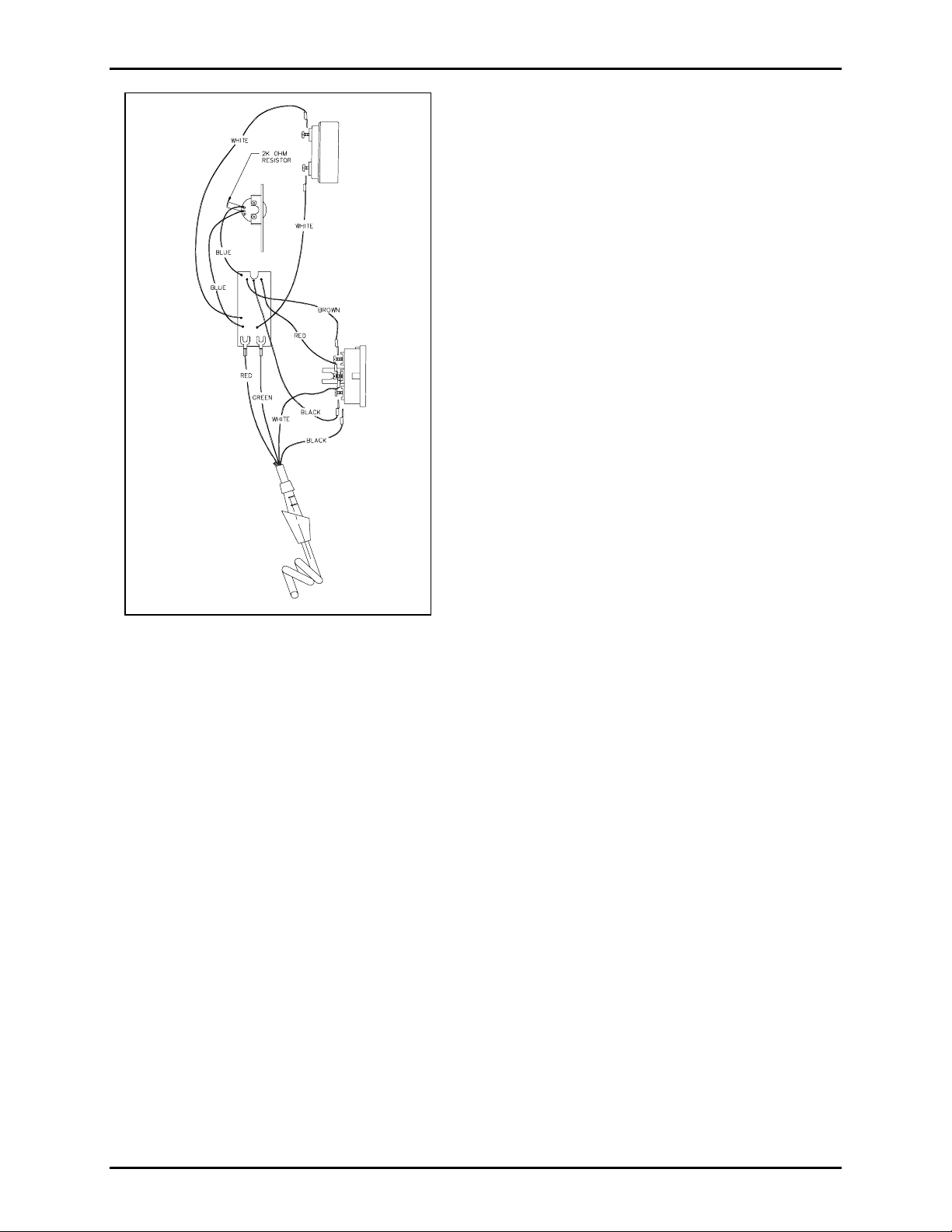
14. Rec onnect the 4 t elephone wires to the PCB A as
follows:
Red to E1 Green to E2
White to E3 Black to E4
Figure 2. Hands et W i ring Diagram
15. Rec onnect the modular telephone wir e to the RJ 11
jack on t he PCBA, and fa sten the front panel to the
rear en closur e.
Models 9001, 9005, 9081, and 9085
Removal of Old Cord
1. Unscrew the 4 front p anel captive sc rews a nd open the fr ont pa nel. Unsna p the blue rib bon cab l e from
the ba c k panel of t he sta tion. Loosen the inter ior hinges a nd remove the front panel.
2. Remove the 5 screws securing the back box to the printed circuit board assembly (PCBA). Remove
the back box.
3. Identify if your s tat ion is an older or a newer model. The older models ha ve an unsecured terminal that
is not anchored to the pr inted circ uit board.
For older models: Disconnect the wires from the PCBA.
Red fr om E1 White from E2 Black f rom E3
Yellow from E4 Blue from E5 Green from the uns ecured t erminal.
For newer models: Disconnect the wires f rom the PCBA.
Red fr om E 1 Green from E2 B lack from E3
Yellow from E4 Blue from E5 White from E7
®
4. When replacing a PVC cord, use a Heyco
bus hing tool or a needle nose pliers to squeeze the not c h on
the fr ont panel s i de of the strain relief bushing and pu ll out the bushing.
5. Feed the bu shing and t he wires through the front p anel to free the cord f rom the panel.
\\s_eng\gtc proddoc s \ s tandard ioms - current release\ 42003 k it m anuals \42003-026c.doc
7/00
Page 4

Pub. 42003-026C
T
HERMOPLASTIC ELASTOMER CORD REPLACEMENT KIT Page: 4 of 11
6. At the handset end, unscrew the transmitter cap and lift out the tr ansmitter. D i sconnect the blac k and
white wires from the transmitter.
7. Unscrew the receiver c ap and lift ou t the r eceiver. Disconnect the red and green wires f rom the
receiver.
8. Using an Allen wrench, loosen the 2 Allen nut s securing the p ressbar. Li f t out the pla stic p ress bar, t he
metal casing, and the 2 pieces of cop per.
9. Lift out the recta ngular pla stic cup a nd disconnect t he b l ue and yellow wires . Pu ll the old cord ou t of
the handset.
Installation of New Cord
10. F eed the red and green wires t hrough t he transmitter end of the handset, thr ough the center of the
hand set to t h e receiv er end. Secure the red and green wires to the recei v er.
11. Place the recei v er into its location. T ighten the receiver cap.
12. F eed the yell ow and the bl ue wir es th rou gh the handset to the pres sbar area.
13. Secure the yellow and blue wires to the terminals in the plastic cup. Place the plastic cup in the
handset.
14. Refer to Figure 1. Place the copper piece with the rubber center in first, with the solid rubber side
fac ing outwa rd.
15. P lace the ot her copp er piece so that the bend faces ou tward.
16. P lace the plast ic piece such that the GAI-Tronics logo side is facing outward. P lace the meta l bra c ket
on top and tight en the Allen screws.
17. Attach the black and white wires to the transmitter.
18. Place the transmitter into its location, making sure that the cord guide snaps firmly onto the cord to
secure it. Tighten the transmitter cap.
19. F eed the ot her end of the cord thr ough the panel from the front of the unit.
20. Us e the new
hands et cord fastener clip to secur e the bushing and the cord to the rear of the front panel.
21. Reconnec t the wires to the PCBA:
For older models:
Red to E1 White to E2 Black to E3
Yellow to E4 Blue to E5 Green to the unsecured terminal
(Insulate with electrical tape or equiv.)
For newer models:
Red to E1 Green to E2 Black to E3
Yellow to E4 Blue to E5 White to E7
22. Secure the back box by tightening the 5 screws.
23. Connect the front panel to the b ack panel by inser ting the hinges in the appropriat e op enings .
24. S ecure the ribbon c able to the bac k section of the station by snapping it int o the appropria te connector
and closing the side t abs .
25. Cl ose the fr ont pa nel and tight en the 4 captive sc rews.
\\s_eng\gtc proddoc s \ s tandard ioms - current release\ 42003 k it m anuals \42003-026c.doc
7/00
Page 5

Pub. 42003-026C
T
HERMOPLASTIC ELASTOMER CORD REPLACEMENT KIT Page: 5 of 11
Models 9101A and 9105A
Removal of Old Cord
1. Remove the 2 mount i ng screws from the mounting br acket. Remove the subset from the mounting
bracket.
2. Remove the 2 top panel screws and the 2 bottom panel screws holding the unit together.
3. Lay the unit op en s o that you can easily a c c es s the printed circuit board assembly (PCBA).
4. Remove the 6 cor d wires from the PC B A:
Red fr om E 1 Green from the right side E2 Black from E3
Yellow from E4 Whit e from the left side of E2 Blue f rom E5
5. When replaci n g an ex i sti n g PVC cor d, u se the Heyco
the notch on the outer side of the st rain relief bushing and pull out the bushing. Pu ll the cord t hrough
the hole and remove the cord.
6. When replacing a thermoplastic elastomer c ord, remove the handset cord fastener clip located on the
bac k side of the front panel. The fastener clip secur es the bus hing and the cord to the front p anel.
7. At the handset end, unscrew the trans mit ter cap, lif t out the transmitter a nd disconnect the black and
white wires.
®
bus hing tool or a needle nose pliers t o squeeze
8. Unscrew the receiver c ap and lift ou t the r eceiver. Disconnect the red and green wires f rom the
receiver.
9. Using the Allen wr ench, loosen the 2 Allen nuts secur ing the pr es sba r. L i f t out the pla stic p ress bar, the
metal casing a nd the 2 pieces of copper.
10. Lif t out the rect angular pl ast ic c up a nd disconnect t he yellow and blue wires. Pull the old cord out of
the handset.
Installation of New Cord
11. F eed the red and green wires t hrough t he transmitter end of the handset, thr ough the center of the
hand set to t h e receiv er end. Secure the red and green wires to the recei v er.
12. Place the recei v er into its location. T ighten the receiver cap.
13. F eed the yellow and blue wires through t he handset pressba r area.
14. Secure the yellow and blue wires to the terminals in the plastic cup. Place the plastic cup in the
handset.
15. Refer to Figure 1. Place the copper piece with the rubber center in first, with the solid rubber side
outward.
16. P lace the ot her copp er piece so that the bend faces ou tward.
17. P lace the plast ic piece so t hat t hat GAI - Tr onic s logo side is facing outwar d. Place the meta l bra c ket on
top and tight en the Allen screws.
18. Attach the black and white wires to the transmitter.
19. Place the transmitter into its location, making sure that the cord guide snaps firmly onto the cord to
secure it. Tighten the transmitter cap.
20. F eed the ot her end of the cord thr ough the panel from the front of the unit.
21. Us e the new
\\s_eng\gtc proddoc s \ s tandard ioms - current release\ 42003 k it m anuals \42003-026c.doc
7/00
handset cord fastener clip to secur e the bushing and the cord to the rear of the front panel.
Page 6

Pub. 42003-026C
T
HERMOPLASTIC ELASTOMER CORD REPLACEMENT KIT Page: 6 of 11
22. Reconnec t the 6 cord wires to the PCBA:
Red to E 1 Green t o the right side E2 Black to E3
Yellow to E4 White to the left side of E2 Blue to E5
23. Replace the 2 top panel screws and the 2 bottom panel screws to reassemble the unit.
24. Use the 2 mounting screws to secure the subset to the mounting bracket.
Models 9201A and 9205A
Removal of Old Cord
1. Remove the unit f rom the wall or the mounti ng surface.
2. Remove the 4 back panel screws.
3. Remove the 6 cor d wires from the PC B A:
Red fr om E 1 Green from the right side E2 Black from E3
Yellow from E4 Whit e from the left side of E2 Blue f rom E5
4. When replaci n g an ex i sti n g PVC cor d, u se the Heyco
the notch on the outer side of the st rain relief bushing and pull out the bushing. Pu ll the cord t hrough
the hole and remove the cord.
5. When replacing a thermoplastic elastomer c ord, remove the handset cord fastener clip located on the
bac k side of the front panel. The fastener clip secur es the bus hing and the cord to the front p anel.
®
bus hing tool or a needle nose pliers t o squeeze
6. At the handset end, unscrew the trans mit ter cap, lif t out the transmitter a nd disconnect the black and
white wires.
7. Unscrew the receiver c ap and lift ou t the r eceiver. Disconnect the red and green wires f rom the
receiver.
8. Using the Allen wr ench, loosen the 2 Allen nuts secur ing the pr es sba r. L i f t out the pla stic p ress bar, the
metal casing a nd the 2 pieces of copper.
9. Lift out the recta ngular pla stic cup a nd disconnect t he yellow and blue wires. Pull the old cord out of
the handset.
Installation of New Cord
10. F eed the red and green wires t hrough t he transmitter end of the handset, thr ough the center of the
hand set to t h e receiv er end. Secure the red and green wires to the recei v er.
11. Place the recei v er into its location. T ighten the receiver cap.
12. F eed the yellow and blue wires through t he handset pressba r area.
13. Secure the yellow and blue wires to the terminals in the plastic cup. Place the plastic cup in the
handset.
14. Refer to Figure 1. Place the copper piece with the rubber center in first, with the solid rubber side
outward.
15. P lace the ot her copp er piece so that the bend faces ou tward.
16. P lace the plast ic piece so t hat t hat GAI - Tr onic s logo side is facing outwar d. Place the meta l bra c ket on
top and tight en the Allen screws.
17. Attach the black and white wires to the transmitter.
18. Place the transmitter into its location, making sure that the cord guide snaps firmly onto the cord to
secure it. Tighten the transmitter cap.
19. F eed the ot her end of the cord thr ough the panel from the front of the unit.
\\s_eng\gtc proddoc s \ s tandard ioms - current release\ 42003 k it m anuals \42003-026c.doc
7/00
Page 7

Pub. 42003-026C
T
HERMOPLASTIC ELASTOMER CORD REPLACEMENT KIT Page: 7 of 11
20. Us e the new handset cord fa stener c lip to secu re the bu shing and t he cord to t he rear of the fr ont pa nel.
21. Reconnec t the 6 cord wires to the PCBA:
Red to E 1 Green t o the right side E2 Black to E3
Yellow to E4 White to the left side of E2 Blue to E5
22. Replace the 4 back panel screws, and remount the unit.
Models 262 and 272 Series
Removal of Old Cord
WARNING
1. Loosen a nd remove the scr ews from the front p anel. P ull the front panel awa y f rom the back
enclosure.
2. Disconnect the 2 signal/ power wir es from t he t erminal block on the rear of the front pa nel.
3. Remove the scr ews securi ng the non-metallic s hield t o the rear of the front p anel.
4. Remove the 4 cord wires f rom the printed circuit board a ssembly (P CBA).
5. Remove the handset cord fast ener clip loca ted on the ba c k side of the front panel. The fastener clip
secures the bushing a nd the cord t o the front pa nel.
!!
Remove main power from the system.
6. Feed the bu shing and t he wires through the front p anel to free the cord f rom the panel.
7. At the handset end, unscrew the transmitter cap and lift out the tr ansmitter. D i sconnect the blac k and
white wires from the transmitter.
8. Unscrew the receiver c ap and lift ou t the r eceiver. Disconnect the red and green wires f rom the
receiver. Pu ll the old cord out of the handset.
Installation of New Cord
9. Snip of f the cord’ s blue and yellow wires as clos e t o their origin as possible.
10. Insert the wire ha rness f rom the new cor d into the ha ndset.
11. Connec t the red and green wires to the r eceiver . Place the r eceiver into its location. Tighten the
receiver ca p .
12. Attach the black and white wires to the transmitter.
13. Place the transmitter into its location, making sure that the cord guide snaps firmly onto the cord to
secure it. Tighten the transmitter cap.
14. F eed the other end of t he cord through the p anel fr om t he front of phone.
15. Us e the new
handset cord fastener clip to secur e the bushing and the cord to the rear of the front panel.
16. Rec onnect the 4 cord wires to the PCBA as follows:
Black to E1 White to E2 Red to E3 Green to E4
17. Secure the wires together with the supplied tie wraps, as necessary.
18. Reattach the non-metallic shield to the rear of the front panel.
19. Rec onnect the 2 signal/ power wir es to the rear terminal block.
20. Remount the unit into the back enclosure and reapply system power.
\\s_eng\gtc proddoc s \ s tandard ioms - current release\ 42003 k it m anuals \42003-026c.doc
7/00
Page 8

Pub. 42003-026C
T
HERMOPLASTIC ELASTOMER CORD REPLACEMENT KIT Page: 8 of 11
Model 701-602
Removal of Old Cord
1. Remove the 4 screws s ecuring the uni t int o the wall encl o sure. Pul l the un i t from th e enclos ure.
2. Loosen the 4 side screws and slide the fr ont pa nel away from the rear s ection. D isconnect the 14-pin
interc onnect cable assembly, located on the right side of the front panel printed circuit board assembly
(PCBA).
3. Lay the front panel to the side to access to the attached PCBA.
4. Rotate the party line selector switch to
Party Li ne 1.
5. Remove the party line s witch pr otective cap by gent ly prying t he front f ace cor ner of the knob up to
expose the pressure grip nut.
6. Loosen the nu t and remove the switch knob .
7. Remove the switc h shaft nut and washer, and set aside. Note the present positioning and orientat ion of
switch PCBA for future PCBA re-assembly.
8. Remove the switch P CBA. Set assembly aside.
9. Carefully cut the tie wraps that secure the cord.
10. Remove the 6 c ord wires f rom the PCBA:
Black f rom E1 White from E2 Red fr om E3
Green from E4 Blue from one side of E6 Yellow from E7
11. Remove the 5 screws that hold the main PCBA to the front panel. Set the PCBA aside.
12. Remove the ha ndset cor d f ast ener c lip located on the ba c k side of the front panel. The fastener clip
secures the bushing a nd the cord t o the front pa nel.
13. F eed the b ushing a nd the wires through the front pa nel and the PCBA to free the cord.
14. At the hands et end, unsc rew the transmitter c ap, lift ou t the transmitter and disconnect the black a nd
white wires.
15. Unsc rew the r eceiver cap and lift out the receiver. Dis c onnect the r ed and green wires from t he
receiver.
16. Using the Allen wrench, loosen the 2 Allen nut s secu ring the press b ar. Lift out the plastic pressba r, the
metal casing, and the 2 pieces of cop per.
17. Lif t out the rect angular pl ast ic c up a nd disconnect t he b l ue and yellow wires . Pu ll the old cord ou t of
the handset.
Installation of New Cord
18. F eed the red and green wires t hrough t he transmitter end of the handset, thr ough the center of the
hand set to t h e receiv er end. Secure the red and green wires to the recei v er.
19. Place the recei v er into its location. T ighten the receiver cap.
20. F eed the yellow and blue wires through t he handset pressba r area.
21. Secure the yellow and blue wires to the terminals in the plastic cup. Place the plastic cup in the
handset.
22. Refer to Figure 1. Place the copper piece with the rubber center in first with the solid rubber side
outward.
23. P lace the ot her copp er piece so that the bend faces ou tward.
\\s_eng\gtc proddoc s \ s tandard ioms - current release\ 42003 k it m anuals \42003-026c.doc
7/00
Page 9

Pub. 42003-026C
T
HERMOPLASTIC ELASTOMER CORD REPLACEMENT KIT Page: 9 of 11
24. P lace the plast ic piece so t hat t hat GAI - Tr onic s logo side is facing outwar d. Place the meta l bra c ket on
top and tight en the Allen screws.
25. Attach the black and white wires to the transmitter.
26. Place the transmitter into its location, making sure that the cord guide snaps firmly onto the cord to
secure it. Tighten the transmitter cap.
27. F eed the ot her end of the cord thr ough the panel from the front of the unit.
28. Us e the new
handset cord fastener clip to secur e the bushing and the cord to the rear of the front panel.
29. Feed the cord through the hole in the PCBA. Reattach the 5 screws and the cord anchor clip that
secures the main PCBA to the front panel.
30. Reconnec t the 6 cord wires to the PCBA:
Black to E1 White to E2 Red to E3
Green to E4 Blue to one side of E6 Yellow to E7
31. Us e the tie wrap to sec ur e the cord wires to th e cord anch or cl i p. Do not block the hole o f the speaker
volume adjus tment.
32. Reins ert t he party line switch PCBA through t he P CBA opening and the front panel. Orient the switch
PCB A s o that the attached cable a ssembly is on t he left side when viewing from the rear of f ront p anel.
33. Reattach the shaft washer and nut and tighten.
34. P lace part y line knob onto the shaft. Realign the knob point er to
Party Li ne 1 and tighten the nut .
35. Reatt ach the front p anel onto t he rear ass embly. Reconnect the 14-pin interc onnec t cab l e assembly
located on the right side into the front panel PCBA. Tighten the 4 cha ssis side screws.
36. Reins tall t he unit into the wall enclos ure.
37. Test t he s tat ion to ensur e that the knob point er is correct ly p ositioned. Turn the switc h to party line 1
and a ttempt to communicat e with another st ation t hat ha s pa rty line 1 selected. If c ommunication is
not pos sible, rotate the knob pointer until communica tions are est ablished, then loosen a nd reposition
the knob pointer a c c ordingly.
38. Reins tall the party line swit c h prot ective cap on the front of the nut.
Models 701-802, 701-804
Removal of Old Cord
1. Remove the 4 screws holding t he u nit into the enclos ure. Remove the unit.
CAUTION
app lic ations . Disc onnect the rib bon cab l e from the unit, if ap plicab le.
2. Loosen the 4 side screws and slide the fr ont panel away from the rear s ection. D isconnect the locking
12-pin interc onnec t cab l e assembly located on the left side fr om t he front p anel PC B A.
3. Remove the tie wraps that secure the cord.
4. Remove the 6 cor d wires from the PC B A:
Black f rom E1 White from E2 Red fr om E3
Green from E4 Blue from one side of E6 Yellow from E7
5. Remove the handset cord fast ener clip loca ted on the ba c k side of the front panel. The fastener clip
secures the bushing a nd the cord t o the front pa nel.
6. When replacing a thermoplastic elastomer c ord, remove the handset cord fastener clip located on the
bac k side of the front panel. The fastener clip secur es the bus hing and the cord to the front p anel.
\\s_eng\gtc proddoc s \ s tandard ioms - current release\ 42003 k it m anuals \42003-026c.doc
7/00
!!
The unit may have a ribbon ca ble at tached to the lower s ide in c erta i n system
Page 10

Pub. 42003-026C
T
HERMOPLASTIC ELASTOMER CORD REPLACEMENT KIT Page: 10 of 11
7. At the handset end, unscrew the trans mit ter cap, lif t out the transmitter a nd disconnect the black and
white wires.
8. Unscrew the receiver c ap and lift ou t the r eceiver. Disconnect the red and green wires f rom the
receiver.
9. Using the Allen wr ench, loosen the 2 Allen nuts secur ing the pr es sba r. L i f t out the pla stic p ress bar, the
metal casing a nd the 2 pieces of copper.
10. Lif t out the rect angular pl ast ic c up a nd disconnect t he yellow and blue wires. Pull the old cord out of
the handset.
Installation of New Cord
11. F eed the red and green wires t hrough t he transmitter end of the handset, thr ough the center of the
hand set to t h e receiv er end. Secure the red and green wires to the recei v er.
12. Place the recei v er into its location. T ighten the receiver cap.
13. F eed the yellow and blue wires through t he handset pressba r area.
14. Secure the yellow and blue wires to the terminals in the plastic cup. Place the plastic cup in the
handset.
15. Refer to Figure 1. Place the copper piece with the rubber center in first, with the solid rubber side
outward.
16. P lace the ot her copp er piece so that the bend faces ou tward.
17. P lace the plast ic piece so t hat t hat GAI - Tr onic s logo side is facing outwar d. Place the meta l bra c ket on
top and tight en the Allen screws.
18. Attach the black and white wires to the transmitter.
19. Place the transmitter into its location, making sure that the cord guide snaps firmly onto the cord to
secure it. Tighten the transmitter cap.
20. F eed the other end of the c ord through the front p anel.
21. Us e the new
handset cord fastener clip to secur e the bushing and the cord to the rear of the front panel.
22. Reconnec t the 6 cord wires to the PCBA:
Black to E1 White to E2 Red to E3
Green to E4 Blue to one side of E6 Yellow to E7
23. S ecure the cord and adjac ent wires by bundling a nd tie wra pping t he exc es s wire length. Ensure that
the cord is directed away from the power supply PCBA.
24. S lide t he front p anel into the rear section. Reconnect t he locking 1 2-pin interconnect c able a ssembly
located on the left si de int o the front pa nel P CBA. Tighten t he 4 side scr ews.
25. Reins tall the unit into the wall enclosure. N ote: Reconnect the enclosure’s r ibbon cable to t he lower
side of unit, if a p plicab le.
\\s_eng\gtc proddoc s \ s tandard ioms - current release\ 42003 k it m anuals \42003-026c.doc
7/00
Page 11

Pub. 42003-026C
T
HERMOPLASTIC ELASTOMER CORD REPLACEMENT KIT Page: 11 of 11
Model 12576-215
Removal of Old Cord
1. Disc onnect the power connector from the rea r of t he subset.
2. Remove the 2 s c rews from the r ear and the 2 screws from t he botto m of subset.
3. Remove the 6 cord wires from the P CBA loca ted under the handset .
Blue from E1 Yellow from E2 White from E5
Black from E6 Green from E7 Red from E8
4. Remove the handset cord fast ener clip loca ted on the left s ide of the bott om assembly.
5. When replacing a thermoplastic elastomer c ord, remove the handset cord fastener clip located on the
bac k side of the front panel. The fastener clip secur es the bus hing and the cord to the front p anel.
6. At the handset end, unscrew the trans mit ter cap, lif t out the transmitter a nd disconnect the black and
white wires.
7. Unscrew the receiver c ap and lift ou t the r eceiver. Disconnect the red and green wires f rom the
receiver.
8. Using the Allen wr ench, loosen the 2 Allen nuts secur ing the pr es sba r. L i f t out the pla stic p ress bar, the
metal casing a nd the 2 pieces of copper.
9. Lift out the recta ngular pla stic cup a nd disconnect t he yellow and blue wires. Pull the old cord out of
the handset.
Installation of New Cord
10. F eed the red and green wires t hrough t he transmitter end of the handset, thr ough the center of the
hand set to t h e receiv er end. Secure the red and green wires to the recei v er.
11. Place the recei v er into its location. T ighten the receiver cap.
12. F eed the yellow and blue wires through t he handset pressba r area.
13. Secure the yellow and blue wires to the terminals in the plastic cup. Place the plastic cup in the
handset.
14. Refer to Figure 1. Place the copper piece with the rubber center in first, with the solid rubber side
outward.
15. P lace the ot her copp er piece so that the bend faces ou tward.
16. P lace the plast ic piece so t hat t hat GAI - Tr onic s logo side is facing outwar d. Place the meta l bra c ket on
top and tight en the Allen screws.
17. Attach the black and white wires to the transmitter.
18. Place the transmitter into its location, making sure that the cord guide snaps firmly onto the cord to
secure it. Tighten the transmitter cap.
19. F eed the other end of t he cord through the p anel from t he side of the su bset.
20. Us e the new
handset c ord fa stener clip to secure the b ushing and the cord t o the left side of the bott om
assembly.
21. Rec onnect the 6 cord wires to the PCBA loca ted under t he handset:
Blue to E1 Yellow to E2 White to E5
Black to E6 Green to E7 Red to E8
22. Reassemble the top and bottom halves of the subset together. Tighten the 4 screws.
23. R econnect the power connect or to the rear of t he subset.
\\s_eng\gtc proddoc s \ s tandard ioms - current release\ 42003 k it m anuals \42003-026c.doc
7/00
Page 12

Warranty
Equipment. GAI-Tronics warrants for a period of one (1) year from the date of shipment, that any
GAI-Tronics equipment supplied hereunder shall be free of defects in material and workmanship, shall
comply with the then-current product specifications and product literature, and if applicable, shall be fit
for the purpose specified in the agreed-upon quotation or proposal document. If (a) Seller’s goods prove
to be defective in workmanship and/or material under normal and proper usage, or unfit for the purpose
specified and agreed upon, and (b) Buyer’s claim is made within the warranty period set forth above,
Buyer may return such goods to GAI-Tronics’ nearest depot repair facility, freight prepaid, at which time
they will be repaired or replaced, at Seller’s option, without charge to Buyer. Repair or replacement shall
be Buyer’s sole and exclusive remedy. The warranty period on any repaired or replacement equipment
shall be the greater of the ninety (90) day repair warranty or one (1) year from the date the original
equipment was shipped. In no event shall GAI-Tronics warranty obligations with respect to equipment
exceed 100% of the total cost of the equipment supplied hereunder. Buyer may also be entitled to the
manufacturer’s warranty on any third-party goods supplied by GAI-Tronics hereunder. The applicability
of any such third-party warranty will be determined by GAI-Tronics.
Services. Any services GAI-Tronics provides hereunder, whether directly or through subcontractors,
shall be performed in accordance with the standard of care with which such services are normally
provided in the industry. If the services fail to meet the applicable industry standard, GAI-Tronics will
re-perform such services at no cost to buyer to correct said deficiency to Company's satisfaction provided
any and all issues are identified prior to the demobilization of the Contractor’s personnel from the work
site. Re-performance of services shall be Buyer’s sole and exclusive remedy, and in no event shall GAITronics warranty obligations with respect to services exceed 100% of the total cost of the services
provided hereunder.
Warranty Periods. Every claim by Buyer alleging a defect in the goods and/or services provided
hereunder shall be deemed waived unless such claim is made in writing within the applicable warranty
periods as set forth above. Provided, however, that if the defect complained of is latent and not
discoverable within the above warranty periods, every claim arising on account of such latent defect shall
be deemed waived unless it is made in writing within a reasonable time after such latent defect is or
should have been discovered by Buyer.
Limitations / Exclusions. The warranties herein shall not apply to, and GAI-Tronics shall not be
responsible for, any damage to the goods or failure of the services supplied hereunder, to the extent
caused by Buyer’s neglect, failure to follow operational and maintenance procedures provided with the
equipment, or the use of technicians not specifically authorized by GAI-Tronics to maintain or service the
equipment. THE WARRANTIES AND REMEDIES CONTAINED HEREIN ARE IN LIEU OF AND
EXCLUDE ALL OTHER WARRANTIES AND REMEDIES, WHETHER EXPRESS OR IMPLIED BY
OPERATION OF LAW OR OTHERWISE, INCLUDING ANY WARRANTIES OF
MERCHANTABILITY OR FITNESS FOR A PARTICULAR PURPOSE.
Return Policy
If the equipment requires service, contact your Regional Service Center for a return authorization number
(RA#). Equipment should be shipped prepaid to GAI-Tronics with a return authorization number and a
purchase order number. If the equipment is under warranty, repairs or a replacement will be made in
accordance with the warranty policy set forth above. Please include a written explanation of all defects to
assist our technicians in their troubleshooting efforts.
Call 800-492-1212 (inside the USA) or 610-777-1374 (outside the USA) for help identifying the
Regional Service Center closest to you.
(Rev. 10/06)
 Loading...