

Page 1

Pub. 42003-243A
GAI-TRONICS® CORPORATION
A HUBBELL COMPANY
PVC Coil Cord Replacement Kit
Models 12514-107, 12514-108, and 12514-109
Confidential ity Notice
This manual is provided solely as an operational, installation, and maintenance guide and contains sensitive
business and technical infor m ation which is con fid ential and proprietary to GAI-Tronics. GAI-Tronics
retains all intellectual property and other rights in or to the information contained herein, and such
information may only be used in connection with the operation of your GAI-Tronics product or system.
This manual may not be disclosed in any form, in whole or in part, directly or indirectly, to any third party.
General Information
These kits are used to replace the PVC cords for handsets with or without a press bar and are used with a
detached strain relief bushing. They are intended for use on the following models:
• 611 • 701-201 • 701-205 • 7165-002 • 701-304 • 701-902
• 6115 • 701-202 • 711-002 • 726-101 • 701-307 • 701-904
• 616 • 701-203 • 7115-002 • 7265-101 • 701-309
• 6165 • 701-204 • 716-002 • 701-302 • 701-312
These kits include the following components:
Qty Description
1 Strain Relief Bushing
1 PVC Cord, 6-foot (Model 12514-107 Kit only)
1 PVC Cord, 15-foot (Model 12514-108 Kit only)
1 PVC Cord, 25-foot (Model 12514-109 Kit only)
Installation
Models without Press Bars
Removing the Old Cord
1. Loosen and remove the screws securing the front panel. Pull the front panel assembly away from the
back enclosure. Retain for re-assembly.
2. Disconnect any connection between the front panel and the PCBA that interferes with the removal of
the front panel. Disconnect the four handset wires from the PCBA, and make note of the connection
locations.
3. If present, remove the E-clip securing the bushing and cord to the rear of the front panel.
GAI-Tronics Corporation 400 E. Wyomissing Ave. Mohnton, PA 19540 USA
610-777-1374 800-492-1212 Fax: 610-796-5954
V
ISIT WWW.GAI-TRONICS.COM FOR PRODUCT LITERATURE AND MANUALS
Page 2
Pub. 42003-243A
ODELS 12514-107, 12514-108, AND 12514-109 PVC COIL CORD REPLACEMENT KIT Page: 2 of 5
M
4. Use a Heyco® bushing tool (preferred), or a set of needle-nose pliers to remove the bushing and cord
from the front panel. If using needle-nose pliers, squeeze the undercut area of the bushing on the
front side of the panel and pull out the cord. Make note of how much of the cord extends past the
bushing.
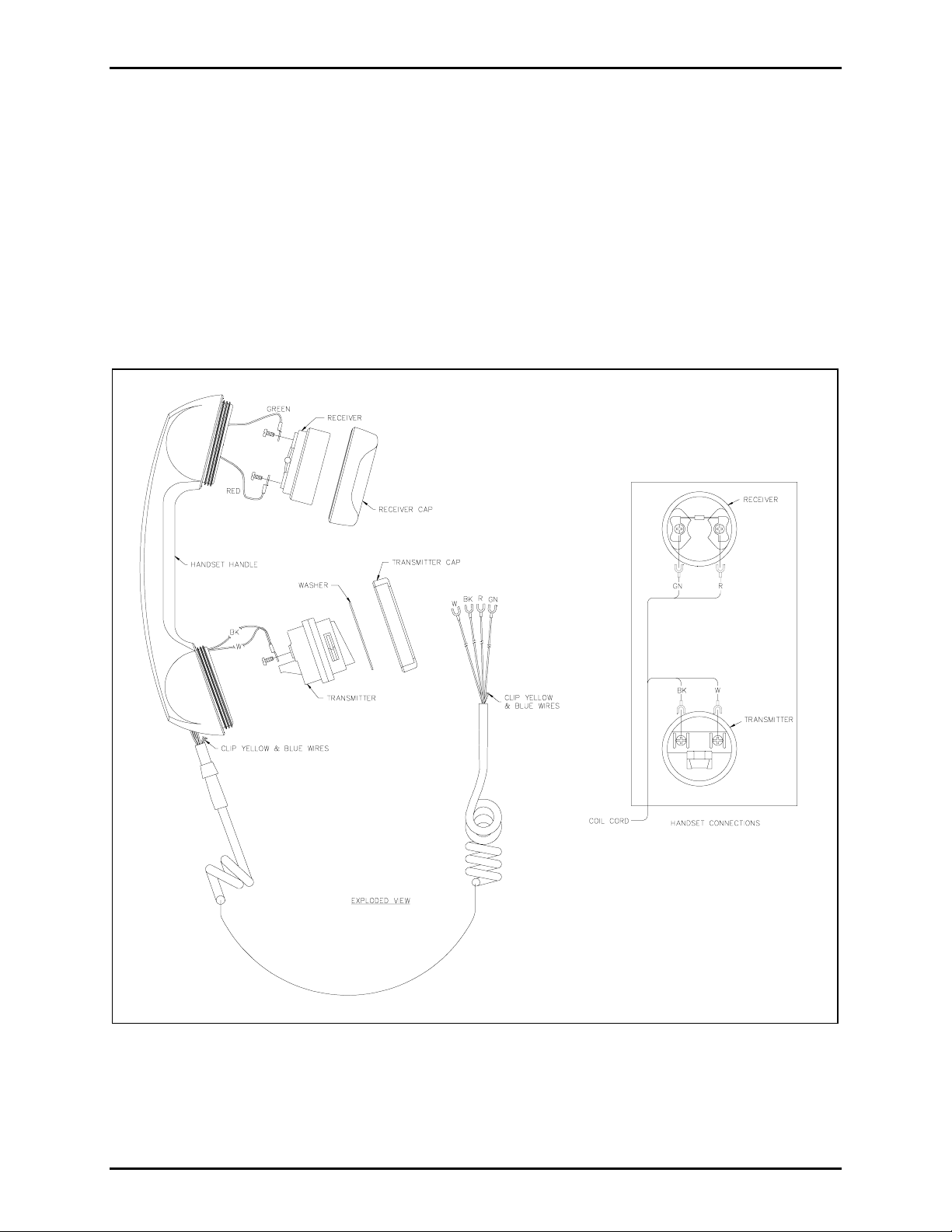
5. Remove the lower cap (transmitter cap) from the handset. Pull out the transmitter, loosen the screws
holding the wires and disconnect the black and white wires. Set aside for re-assembly. Make note of
the orientation of the transmitter. Refer to Figure 1.
6. Remove the upper cap (receiver cap) from the handset handle. Set aside for re-assembly. Pull out the
receiver, loosen the screws holding the wires and disconnect the green and red wires.
7. Pull the wire harness out of the handset and discard the cord.
Figure 1. Handset Assembly
f:\standard ioms - current release\42003 kit manuals\42003-243a.doc
01/12
Page 3

Pub. 42003-243A
ODELS 12514-107, 12514-108, AND 12514-109 PVC COIL CORD REPLACEMENT KIT Page: 3 of 5
M
Installing the New Cord
1. Clip the blue and yellow wires from both ends of the new cord as close to the insulation as possible.
2. Thread the wires through the handset. The black and white wires should protrude out of the
transmitter end of the handset, and the red and green wires out of the receiver end.
3. Reconnect the black and white wires to the transmitter using existing screws. Orient the transmitter
so that the U-slot on the transmitter surrounds the molded bushing of the coil cord and “GTC” is at
the 6 o’clock position in the handset handle cavity. Secure with the transmitter cap.
4. Reconnect the red and green wires to the receiver using the existing screws. Reinstall the receiver
and secure using the receiver cap.
5. Insert the plain end of the coil cord into the strain relief bushing and close the bushing. See Figure 2.
Figure 2. Strain Relief Bushing Assembly
®
6. Use the Heyco
bushing tool to squeeze the Heyco® bushing back into the front panel opening.
7. Reconnect the four handset wires to the E-clips previously noted and any other appropriate
connections.
8. Secure the front panel to the back of the enclosure with the screws previously retained.
Models with Press Bar Handset
Removing the Old Cord
1. Loosen and remove the screws securing the front panel. Pull the front panel assembly away from the
back enclosure. Retain for re-assembly.
2. Disconnect any connection between the front panel and the PCBA that interferes with the removal of
the front panel. Disconnect the six handset wires from the PCBA and make note of the connection
locations.
3. If present, remove the E-clip securing the bushing and cord to the rear of the front panel.
®
4. Use a Heyco
from the front panel. If using needle-nose pliers, squeeze the undercut area of the bushing on the
front side of the panel and pull out with the cord. Make note of how much of the cord extends past
the bushing.
bushing tool (preferred), or a set of needle-nose pliers to remove the bushing and cord
f:\standard ioms - current release\42003 kit manuals\42003-243a.doc
01/12
Page 4

Pub. 42003-243A
ODELS 12514-107, 12514-108, AND 12514-109 PVC COIL CORD REPLACEMENT KIT Page: 4 of 5
M
5. Remove the lower cap (transmitter cap) from the handset handle. Set aside for re-assembly. Make
note the orientation of the transmitter. Pull out the transmitter, loosen the screws holding the wires
and disconnect the black and white wires. Refer to Figure 3.
Figure 3. Handset Assembly with Press Bar
6. Remove the upper cap (receiver cap) from the handset handle. Set aside for re-assembly. Pull out the
receiver, loosen the screws holding the wires and disconnect the green and red wires.
7. Remove the press bar assembly by removing the flat-head screws securing it to the handset handle.
Remove the switch assembly from the cavity and loosen the screws for the blue and yellow wires and
disconnect.
8. Pull the wire harness out of the handset and discard the cord.
f:\standard ioms - current release\42003 kit manuals\42003-243a.doc
01/12
Page 5

Pub. 42003-243A
ODELS 12514-107, 12514-108, AND 12514-109 PVC COIL CORD REPLACEMENT KIT Page: 5 of 5
M
Installing the New Cord
1. Thread the wires through the handset. The black and white wires should protrude out the transmitter
end of the handset, the red and green wires out the receiver end and the blue and yellow wires out the
center cavity. Push the molded bushing into the handset handle as far as possible.
2. Reconnect the black and white wires to the transmitter using the existing screws. Orient the
transmitter so the U-slot on the transmitter surrounds the molded bushing of the coil cord and the
“GTC” is at the 6 o’clock position in the handset hand l e cavity . Secure with the tr ansmitter cap.
3. Reconnect the red and green wires to the receiver using the existing screws. Push the receiver into
the handset receiver cavity, and secure with the receiver cap.
4. Reconnect the blue and yellow wires to the switch using the existing screws. Reinstall the switch
assembly into the center handset cavity.
5. Insert the plain end of the coil cord into the strain relief bushing and close the bushing. Refer to
Figure 2 on page 3.
6. Use the Heyco
®
bushing tool to squeeze the Heyco® bushing back into the front panel opening.
7. Reconnect the six handset wires to E-clips previously noted and make any other appropriate
connections.
8. Secure the front panel to the back of the enclosure with the screws previously retained.
f:\standard ioms - current release\42003 kit manuals\42003-243a.doc
01/12
Page 6

Warranty
Equipment. GAI-Tronics warrants for a period of one (1) year from the date of shipment, that any
GAI-Tronics equipment supplied hereunder shall be free of defects in material and workmanship, shall
comply with the then-current product specifications and product literature, and if applicable, shall be fit
for the purpose specified in the agreed-upon quotation or proposal document. If (a) Seller’s goods prove
to be defective in workmanship and/or material under normal and proper usage, or unfit for the purpose
specified and agreed upon, and (b) Buyer’s claim is made within the warranty period set forth above,
Buyer may return such goods to GAI-Tronics’ nearest depot repair facility, freight prepaid, at which time
they will be repaired or replaced, at Seller’s option, without charge to Buyer. Repair or replacement shall
be Buyer’s sole and exclusive remedy. The warranty period on any repaired or replacement equipment
shall be the greater of the ninety (90) day repair warranty or one (1) year from the date the original
equipment was shipped. In no event shall GAI-Tronics warranty obligations with respect to equipment
exceed 100% of the total cost of the equipment supplied hereunder. Buyer may also be entitled to the
manufacturer’s warranty on any third-party goods supplied by GAI-Tronics hereunder. The applicability
of any such third-party warranty will be determined by GAI-Tronics.
Services. Any services GAI-Tronics provides hereunder, whether directly or through subcontractors,
shall be performed in accordance with the standard of care with which such services are normally
provided in the industry. If the services fail to meet the applicable industry standard, GAI-Tronics will
re-perform such services at no cost to buyer to correct said deficiency to Company's satisfaction provided
any and all issues are identified prior to the demobilization of the Contractor’s personnel from the work
site. Re-performance of services shall be Buyer’s sole and exclusive remedy, and in no event shall GAITronics warranty obligations with respect to services exceed 100% of the total cost of the services
provided hereunder.
Warranty Periods. Every claim by Buyer alleging a defect in the goods and/or services provided
hereunder shall be deemed waived unless such claim is made in writing within the applicable warranty
periods as set forth above. Provided, however, that if the defect complained of is latent and not
discoverable within the above warranty periods, every claim arising on account of such latent defect shall
be deemed waived unless it is made in writing within a reasonable time after such latent defect is or
should have been discovered by Buyer.
Limitations / Exclusions. The warranties herein shall not apply to, and GAI-Tronics shall not be
responsible for, any damage to the goods or failure of the services supplied hereunder, to the extent
caused by Buyer’s neglect, failure to follow operational and maintenance procedures provided with the
equipment, or the use of technicians not specifically authorized by GAI-Tronics to maintain or service the
equipment. THE WARRANTIES AND REMEDIES CONTAINED HEREIN ARE IN LIEU OF AND
EXCLUDE ALL OTHER WARRANTIES AND REMEDIES, WHETHER EXPRESS OR IMPLIED BY
OPERATION OF LAW OR OTHERWISE, INCLUDING ANY WARRANTIES OF
MERCHANTABILITY OR FITNESS FOR A PARTICULAR PURPOSE.
Return Policy
If the equipment requires service, contact your Regional Service Center for a return authorization number
(RA#). Equipment should be shipped prepaid to GAI-Tronics with a return authorization number and a
purchase order number. If the equipment is under warranty, repairs or a replacement will be made in
accordance with the warranty policy set forth above. Please include a written explanation of all defects to
assist our technicians in their troubleshooting efforts.
Call 800-492-1212 (inside the USA) or 610-777-1374 (outside the USA) for help identifying the
Regional Service Center closest to you.
(Rev. 10/06)
 Loading...