

Page 1

Pub. 42003-023E
GAI-TRONICS® CORPORATION
A HUBBELL COMPANY
Hookswitch Assembly
Replacement Kit
Model 12512-001
Confidential ity Notice
This manual is provided solely as an operational, installation, and maintenance guide and contains
sensitive business and technical information that is confidential and proprietary to GAI-Tronics.
GAI-Tronics retains all intellectual property and other rights in or to the information contained herein,
and such information may only be used in connection with the operation of your GAI-Tronics product or
system. This manual may not be disclosed in any form, in whole or in part, directly or indirectly, to any
third party.
General Information
The Model 12512-001 Hookswitch Assembly Replacement Kit is designed for use on the following
telephones:
24x Series 272-001
25x Series 341-001
262-001 351-001
Qty Description
1 Cradle/Hookswitch Assembly
2 Screws
1 Cable tie
1 Gasket
Models 246-001, 24 7-001, 256-001, 257-001, 34 1-001
& 351-001
Removal of Old Assembly
1. Remove the front cover screws and pull front cover away from back box/enclosure. Retain the
screws.
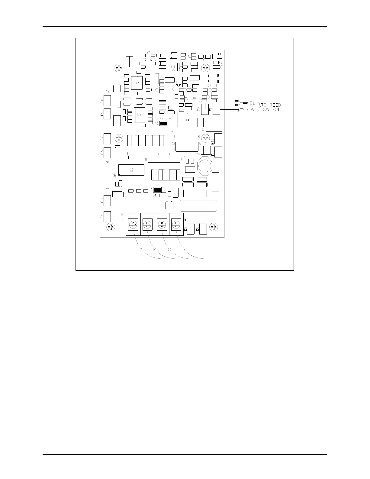
2. Disconnect the red (Ring) and green (Tip) wires from TB1. See Figure 2.
3. Disconnect the blue and white reed switch wires from the PCBA at E1 and E2.
GAI-Tronics Corporation 400 E. Wyomissing Ave. Mohnton, PA 19540 USA
610-777-1374 800-492-1212 Fax: 610-796-5954
V
ISIT WWW.GAI-TRONICS.COM FOR PRODUCT LITERATURE AND MANUALS
Page 2
Pub. 42003-023E
ODEL 12512-001 HOOKSWITCH ASSEMBLY REPLACEMENT KIT Page 2 of 8
M
4. Cut the cable tie used to bundle wires together.
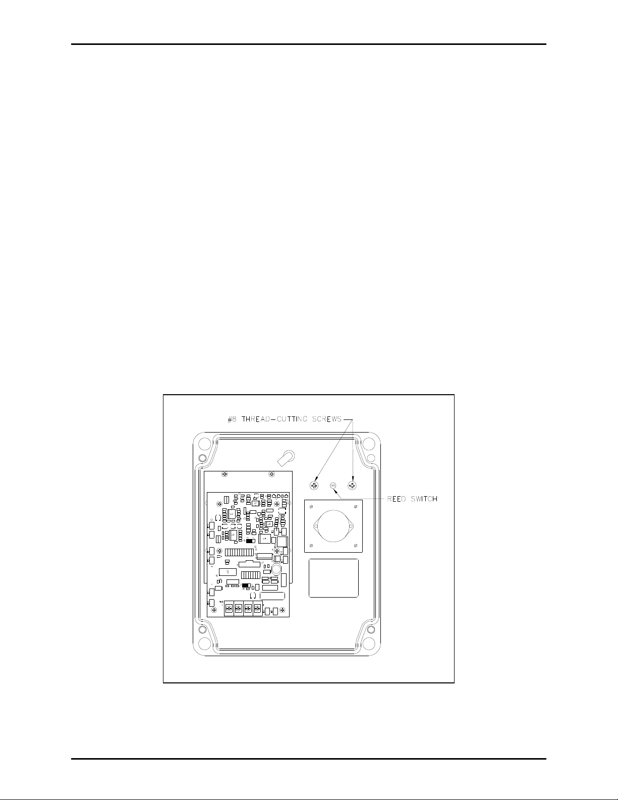
5. Remove the two screws that secure the handset cradle to the front cover. See Figure 1.
6. Pull the handset cradle with the reed switch attached away from the front panel.
7. Remove the handset cradle gasket from the front panel (if necessary).
Installing New Assembly
8. Cut the black wire lead close to the switch body and discard.
9. Thread the blue and white reed switch leads through the center top hole. See Figure 1.
10. Secure the plastic cradle on the front cover using the two #8 thread-cutting screws. See Figure 1.
11. Plug spades on the blue and white wires into E1 and E2 on the PCBA. See Figure 2.
12. Bundle the wires as before with the cable tie included in the kit.
13. Reconnect the red and green wires to TB1. See Figure 2.
14. Replace the front panel and secure using the screws retained from step 1.
15. Test the on-hook/off-hook function to ensure installation has been successful.
f:\standard ioms - current release\42003 kit manuals \42003-023e. doc
08/14
Figure 1.
Page 3
Pub. 42003-023E
ODEL 12512-001 HOOKSWITCH ASSEMBLY REPLACEMENT KIT Page 3 of 8
M
Figure 2. Industrial Telephone PCBA
f:\standard ioms - current release\42003 kit manuals \42003-023e. doc
08/14
Page 4

Pub. 42003-023E
ODEL 12512-001 HOOKSWITCH ASSEMBLY REPLACEMENT KIT Page 4 of 8
M
Models 262-001 and 272-001
Removal of Old Assembly
1. Remove the front cover screws and pull front cover away from back box/enclosure. Retain the
screws.
2. Disconnect the red (Ring) and green (Tip) wires from TB1. See Figure 3.
3. Disconnect the blue, white, and black reed switch wires from the PCBA at E1, E2 and E3.
4. Cut the cable tie used to bundle wires together.
5. Remove the two screws that secure the handset cradle to the front cover. See Figure 1.
6. Pull the handset cradle with the reed switch attached away from the front panel.
7. Remove the handset cradle gasket from the front panel (if necessary).
Installing New Assembly
8. Thread the reed switch leads through the center top hole. See Figure 1.
9. Secure the plastic cradle on the front cover using the two #8 thread-cutting screws. See Figure 1.
10. Plug spades on the blue, white, and black wires into E1, E2, and E3 respectively on the PCBA. See
Figure 3.
11. Bundle the wires as before with the cable tie included in the kit.
12. Reconnect the red and green wires to TB1. See Figure 3.
13. Replace the front panel and secure using the screws retained from step 1.
14. Test the on-hook/off-hook function to ensure installation has been successful.
f:\standard ioms - current release\42003 kit manuals \42003-023e. doc
08/14
Page 5

Pub. 42003-023E
ODEL 12512-001 HOOKSWITCH ASSEMBLY REPLACEMENT KIT Page 5 of 8
M
Figure 3. I.S. Telephone PCBA (for Models 262-001 and 272-001 only)
f:\standard ioms - current release\42003 kit manuals \42003-023e. doc
08/14
Page 6

Pub. 42003-023E
ODEL 12512-001 HOOKSWITCH ASSEMBLY REPLACEMENT KIT Page 6 of 8
M
Models 24x-003, 24 x-005, 25x-003, 25x-005, 24 6-700
& 256-700
Removing Old Assembly
1. Remove the front cover screws and pull the front cover away from the back box/enclosure. Retain
the screws.
2. For Models 24x-003 and 24x-005: Disconnect the red (Ring) and green (Tip) wires from TB1. See
Figure 5 and Figure 6.
3. For Models 246-700 and 256-700: Disconnect power plug (P11).
4. Cut the cable tie used to bundle the wires together.
5. Remove the three screws securing the PCBA mounting bracket to the panel. Retain the screws for
reassembly.
6. Remove the remaining screw that secures the handset cradle to the front cover. See Figure 4.
7. Pull the handset cradle with the reed switch attached away from the front panel.
8. Remove the handset cradle gasket from the front panel (if necessary).
Install New Assembly
9. Thread the leads of the reed switch through the center top hole. See Figure 4.
10. Secure the plastic cradle on the front cover using the #8 thread cutting screw. See Figure 4.
11. Secure the PCBA mounting bracket using the three screws removed in step 5 above. Note the upper
right screw is a #8 thread cutting screw and also secures the handset cradle.
12. Plug spades on the blue and white wires into appropriate E-clips on the PCBA. For models with the
suffixes -005 and -700, see Figure 6 and Figure 7.
For models with the suffix -003, clip off spade lugs and strip the w ire ¼ inch and instal l the lead s into
TB7. See Figure 5.
13. Bundle wires as before with the cable tie included in the kit.
14. For Models 24x-003 and 24x-005, reconnect the red (Ring) and green (Tip) wires to TB1. For
Models 246-700 and 256-700, reconnect the power cord to P11 on the PCBA.
15. Replace the front cover and secure using screws retained from step 1.
16. Test the on-hook/off-hook function to ensure installation has been successful.
f:\standard ioms - current release\42003 kit manuals \42003-023e. doc
08/14
Page 7

Pub. 42003-023E
ODEL 12512-001 HOOKSWITCH ASSEMBLY REPLACEMENT KIT Page 7 of 8
M
Figure 4.
Figure 5. Emergency/Smart Telephone PCBA (for Models 24x-003 and 25x-003)
f:\standard ioms - current release\42003 kit manuals \42003-023e. doc
08/14
Page 8

Pub. 42003-023E
ODEL 12512-001 HOOKSWITCH ASSEMBLY REPLACEMENT KIT Page 8 of 8
M
Figure 6. Smart Handset Telephone PCBA (for Models 24x-005 and 25x-005)
Figure 7. VoIP Carrier PCBA and VoIP Circuit PCBA (for Models 246-700 and 256-700)
f:\standard ioms - current release\42003 kit manuals \42003-023e. doc
08/14
Page 9

Warranty
Equipment. GAI-Tronics warrants for a period of one (1) year from the date of shipment, that any
GAI-Tronics equipment supplied hereunder shall be free of defects in material and workmanship, shall
comply with the then-current product specifications and product literature, and if applicable, shall be fit
for the purpose specified in the agreed-upon quotation or proposal document. If (a) Seller’s goods prove
to be defective in workmanship and/or material under normal and proper usage, or unfit for the purpose
specified and agreed upon, and (b) Buyer’s claim is made within the warranty period set forth above,
Buyer may return such goods to GAI-Tronics’ nearest depot repair facility, freight prepaid, at which time
they will be repaired or replaced, at Seller’s option, without charge to Buyer. Repair or replacement shall
be Buyer’s sole and exclusive remedy. The warranty period on any repaired or replacement equipment
shall be the greater of the ninety (90) day repair warranty or one (1) year from the date the original
equipment was shipped. In no event shall GAI-Tronics warranty obligations with respect to equipment
exceed 100% of the total cost of the equipment supplied hereunder. Buyer may also be entitled to the
manufacturer’s warranty on any third-party goods supplied by GAI-Tronics hereunder. The applicability
of any such third-party warranty will be determined by GAI-Tronics.
Services. Any services GAI-Tronics provides hereunder, whether directly or through subcontractors,
shall be performed in accordance with the standard of care with which such services are normally
provided in the industry. If the services fail to meet the applicable industry standard, GAI-Tronics will
re-perform such services at no cost to buyer to correct said deficiency to Company's satisfaction provided
any and all issues are identified prior to the demobilization of the Contractor’s personnel from the work
site. Re-performance of services shall be Buyer’s sole and exclusive remedy, and in no event shall GAITronics warranty obligations with respect to services exceed 100% of the total cost of the services
provided hereunder.
Warranty Periods. Every claim by Buyer alleging a defect in the goods and/or services provided
hereunder shall be deemed waived unless such claim is made in writing within the applicable warranty
periods as set forth above. Provided, however, that if the defect complained of is latent and not
discoverable within the above warranty periods, every claim arising on account of such latent defect shall
be deemed waived unless it is made in writing within a reasonable time after such latent defect is or
should have been discovered by Buyer.
Limitations / Exclusions. The warranties herein shall not apply to, and GAI-Tronics shall not be
responsible for, any damage to the goods or failure of the services supplied hereunder, to the extent
caused by Buyer’s neglect, failure to follow operational and maintenance procedures provided with the
equipment, or the use of technicians not specifically authorized by GAI-Tronics to maintain or service the
equipment. THE WARRANTIES AND REMEDIES CONTAINED HEREIN ARE IN LIEU OF AND
EXCLUDE ALL OTHER WARRANTIES AND REMEDIES, WHETHER EXPRESS OR IMPLIED BY
OPERATION OF LAW OR OTHERWISE, INCLUDING ANY WARRANTIES OF
MERCHANTABILITY OR FITNESS FOR A PARTICULAR PURPOSE.
Return Policy
If the equipment requires service, contact your Regional Service Center for a return authorization number
(RA#). Equipment should be shipped prepaid to GAI-Tronics with a return authorization number and a
purchase order number. If the equipment is under warranty, repairs or a replacement will be made in
accordance with the warranty policy set forth above. Please include a written explanation of all defects to
assist our technicians in their troubleshooting efforts.
Call 800-492-1212 (inside the USA) or 610-777-1374 (outside the USA) for help identifying the
Regional Service Center closest to you.
(Rev. 10/06)
 Loading...