

Page 1

Pub. 42003-219A
GAI-TRONICS® CORPORATION
A HUBBELL COMPANY
Replacement Door Kit
for Weathe rpro of Enclosures
Model 12505-101
Confidentiality Notice
This manua l is provide d sole ly as an operatio nal, installation, and ma inte nance guide and conta ins
sensitive business and t e chnical informatio n tha t is confidentia l and pr opri et ary to GAI- Tronics.
GAI-Tronics retains all intellectual property and other rights in or to the information contained herein,
and such information may only be used in connection with the operation of your GAI-Tronics product or
system. This manu al may not be dis clos e d in any form, in whole or in pa rt, direct ly or i ndir ectly, to a ny
third pa r ty.
General Information
The Model 12505-101 Replacement Door Kit is for use on the GAI-Tronics Model 7325-106
Weatherproof Enclosures. This kit includes the following components:
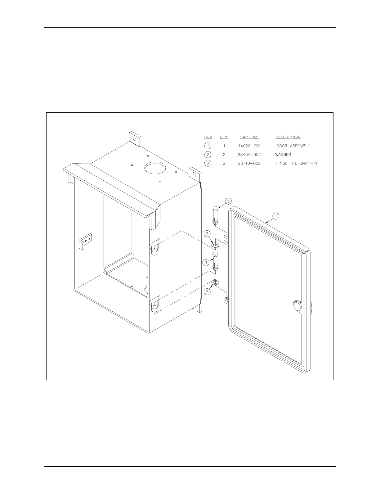
Item Qty. Description
1 1 Door Assembly with Gasket
2 2 Washer
3 2 Hinge pin, Snap-in
Installation
Unpack the material and compare parts to the list below to ensure that all parts are present.
N
OTE: A pair of needle-nose pliers required for some assembly.
1. Remove each of t he two hinge pins by compressing the sl otte d e nd wit h a pair of ne e dle-nose plier s
and drivi ng it back throug h the h ole.
2. Aft er removing the old door fr om the e nclos ur e, chec k the fi t an d c lear ance of the replaceme nt door
by placing the door assembly onto the enclosure. Place the first of the two washers (item 2) beneath
the upper door hinge and over the upper enclosure hinge bosses. Place the second washer beneath the
lower enclosure hinge and over the top of the lower door hinge bosses. File the material from the
door bosses if more clearance is required. See Figure 1.
GAI-Tronics Corporation 400 E. Wyomissing Av e. Mohnton, PA 19540 USA
610-777-1374 800-492-1212 Fax: 610-796-5954
ISIT WWW.GAI-TRONICS.COM FOR PRODUCT LITERATURE AND MANUALS
V
Page 2
Pub. 42003-219A
M
ODEL 12505-101 REPLACEMENT DOOR KIT Page: 2 of 2
3. Posi tion the d oor assembly onto t he enc losure a nd place one washer ( i tem 2) ben eath the upper do or
boss and ov er the enclosure boss. Insert the slotted end of t he pin as s hown in Figure 1 a nd in a
downward direction, drive it through the holes of the door boss, washer, and enclosure boss.
4. Place one washer (item 2) beneath the lower enclosure boss and over the door boss. Insert the lower
hing e pin, and in a do w nward direction dr ive the hi nge p in through the h oles of the e nclos ure boss,
washer, and door boss.
Figure 1. Replacement Door Assembly
\\s_eng\gtc proddoc s \st andard iom s - current release\42003 kit manuals \ 42003-219a.doc
08/08
 Loading...