

Page 1

Pub. 42003-008A
GAI-TRONICS® CORPORATION
A HUBBELL COMPANY
Replacement Door Kit
for Weathe rpro of Enclosures
Model 12505-001
Confidentiality Notice
This manua l is provide d sole ly as an operatio nal, installation, and ma inte nance guide and conta ins
sensitive business and t e chnical informatio n tha t is confidentia l and pr opri et ary to GAI- Tronics.
GAI-Tronics retains all intellectual property and other rights in or to the information contained herein,
and such information may only be used in connection with the operation of your GAI-Tronics product or
system. This manu al may not be dis clos e d in any form, in whole or in pa rt, direct ly or i ndir ectly, to a ny
third pa r ty.
General Information
The Model 12505-001 Replacement Door Kit is for use on the following GAI-Tronics weatherproof
enclosures:
632 648 732 10437-001 10437-003
6325 6485 7325 10437-002 211A
This kit includes the following components:
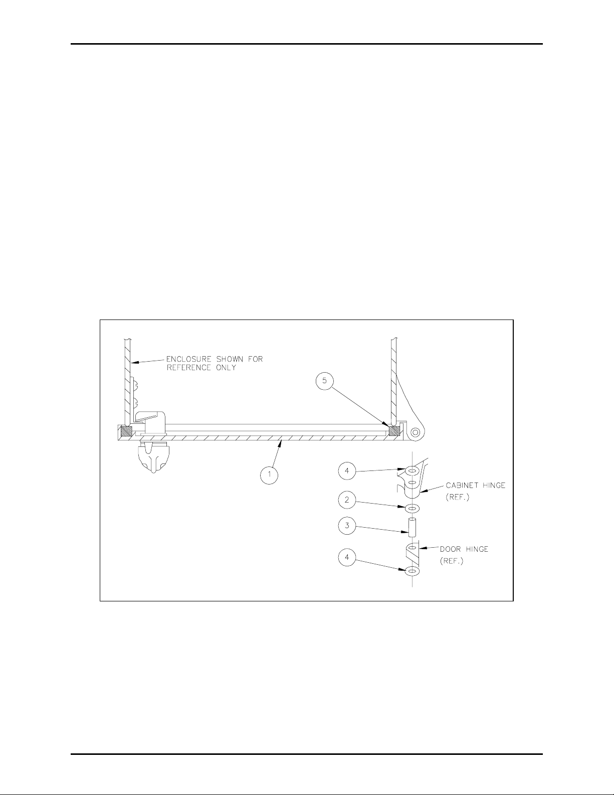
Item Qty. Description
1 1 Door
2 2 Washer
3 2 Hinge pin
4 4 Pin retainer
5 1 Gasket
Installation
Unpack the material and compare parts to the list below to ensure that all parts are present.
(N
OTE: A ¼-inch hex nut driver is required for some assembly.)
1. Remove the two hinge pins by driving the upper pin downward and the lower pin upward.
2. Aft er removing the old door fr om the e nclos ur e, chec k the fi t an d c lear ance of the replaceme nt door
by placing the door assembly onto the enclosure. Place two washers (item 2) between the upper and
lower door and enclosure hinge bosses. File the material from the door bosses if more clearance is
required.
GAI-Tronics Corporation P.O. Box 1060, Readi ng, PA 19607-1060 USA
610-777-1374 800-492-1212 Fax: 610-796-5954
ISIT WWW.GAI-TRONICS.COM FOR PRODUCT LITERATURE AND MANUALS
V
Page 2
Pub. 42003-008A
M
ODEL 12505-001 REPLACEMENT DOOR KIT Page: 2 of 2
3. After ensuring proper fit and clearance, slide one pin retainer (item 4) onto each hinge pin (item 3).
Position the pin retainer such that it is 1/16 inch from the end of the hinge pin.
4. Position the door assembly onto the enclosure and place one washer (item 2) between the upper door
boss and the enclosure boss. In an upward position, insert the pin, with the retainer installed, through
hinge pin holes of the enclosure boss, washer, and door boss.
5. Insert the lower hinge pin, with the retainer installed, in a downward direction through the hinge pin
holes in the enclosure boss, washer and door boss.
6. Install the upper pin retainer by placing it on top of the upper hinge pin and then pushing downward
with the ¼-inch hex nut driver, while at the same time applying pressure at the bottom of the hinge
pin. The pin retainer should be pushed onto the hinge until both pin retainers are touching the bosses
of th e door and enc losure.
7. Place the pin retainer on the opening of the ¼-inch hex nut driver and by pushing upward, install onto
the lower hinge pin, while applying downward pressure on the hin ge pin. Pin retainers should tou ch
the b osses of th e door and enclosure.
Figure 1.
\\s_eng\gtc proddoc s \st andard iom s - current release\42003 kit manuals \ 42003-008a.doc
6/96
Page 3

Warranty
Equipment. GAI-Tronics warrants for a period of one (1) year from the date of shipment, that any
GAI-Tronics equipment supplied hereunder shall be free of defects in material and workmanship, shall
comply with the then-current product specifications and product literature, and if applicable, shall be fit
for the purpose specified in the agreed-upon quotation or proposal document. If (a) Seller’s goods prove
to be defective in workmanship and/or material under normal and proper usage, or unfit for the purpose
specified and agreed upon, and (b) Buyer’s claim is made within the warranty period set forth above,
Buyer may return such goods to GAI-Tronics’ nearest depot repair facility, freight prepaid, at which time
they will be repaired or replaced, at Seller’s option, without charge to Buyer. Repair or replacement shall
be Buyer’s sole and exclusive remedy. The warranty period on any repaired or replacement equipment
shall be the greater of the ninety (90) day repair warranty or one (1) year from the date the original
equipment was shipped. In no event shall GAI-Tronics warranty obligations with respect to equipment
exceed 100% of the total cost of the equipment supplied hereunder. Buyer may also be entitled to the
manufacturer’s warranty on any third-party goods supplied by GAI-Tronics hereunder. The applicability
of any such third-party warranty will be determined by GAI-Tronics.
Services. Any services GAI-Tronics provides hereunder, whether directly or through subcontractors,
shall be performed in accordance with the standard of care with which such services are normally
provided in the industry. If the services fail to meet the applicable industry standard, GAI-Tronics will
re-perform such services at no cost to buyer to correct said deficiency to Company's satisfaction provided
any and all issues are identified prior to the demobilization of the Contractor’s personnel from the work
site. Re-performance of services shall be Buyer’s sole and exclusive remedy, and in no event shall GAITronics warranty obligations with respect to services exceed 100% of the total cost of the services
provided hereunder.
Warranty Periods. Every claim by Buyer alleging a defect in the goods and/or services provided
hereunder shall be deemed waived unless such claim is made in writing within the applicable warranty
periods as set forth above. Provided, however, that if the defect complained of is latent and not
discoverable within the above warranty periods, every claim arising on account of such latent defect shall
be deemed waived unless it is made in writing within a reasonable time after such latent defect is or
should have been discovered by Buyer.
Limitations / Exclusions. The warranties herein shall not apply to, and GAI-Tronics shall not be
responsible for, any damage to the goods or failure of the services supplied hereunder, to the extent
caused by Buyer’s neglect, failure to follow operational and maintenance procedures provided with the
equipment, or the use of technicians not specifically authorized by GAI-Tronics to maintain or service the
equipment. THE WARRANTIES AND REMEDIES CONTAINED HEREIN ARE IN LIEU OF AND
EXCLUDE ALL OTHER WARRANTIES AND REMEDIES, WHETHER EXPRESS OR IMPLIED BY
OPERATION OF LAW OR OTHERWISE, INCLUDING ANY WARRANTIES OF
MERCHANTABILITY OR FITNESS FOR A PARTICULAR PURPOSE.
Return Policy
If the equipment requires service, contact your Regional Service Center for a return authorization number
(RA#). Equipment should be shipped prepaid to GAI-Tronics with a return authorization number and a
purchase order number. If the equipment is under warranty, repairs or a replacement will be made in
accordance with the warranty policy set forth above. Please include a written explanation of all defects to
assist our technicians in their troubleshooting efforts.
Call 800-492-1212 (inside the USA) or 610-777-1374 (outside the USA) for help identifying the
Regional Service Center closest to you.
(Rev. 10/06)
 Loading...