

Page 1

Pub. 42003-218B
GAI-TRONICS® CORPORATION
A HUBBELL COMPANY
Keypad Replacement Kit for
Model 491-204 Mine Dial Page Telephone
Model 12504-010
Confidentiality Notice
This manual is provided solely as an operational, installation, and maintenance guide and contains
sensitive business and technical information that is confidential and proprietary to GAI-Tronics.
GAI-Tronics retains all intellectual property and other rights in or to the information contained herein,
and such information may only be used in connection with the operation of your GAI-Tronics product or
system. This manual may not be disclosed in any form, in whole or in part, directly or indirectly, to any
third party.
General Information
The Model 12504-010 Keypad Replacement Kit for the Model 491-204 Mine Dial Page Telephone
includes the following components:
Qty Description
1 Keypad assembly
1 Keypad seal
1 Resistor, 100-ohm, 3-watt, WW or MF
3 Cable tie-wrap
Installation
Tools Required
• 5/16-inch nut driver
• 1/4-inch nut driver
• Phillips screwdriver
• Wire cutter
CAUTION
technician or by a GAI-Tronics authorized service center. Installation by any other service center
or personnel will void MSHA approval.
WARNING
This upgrade replacement kit may only be installed by a GAI-Tronics
Substitution of components may impair intrinsic safety.
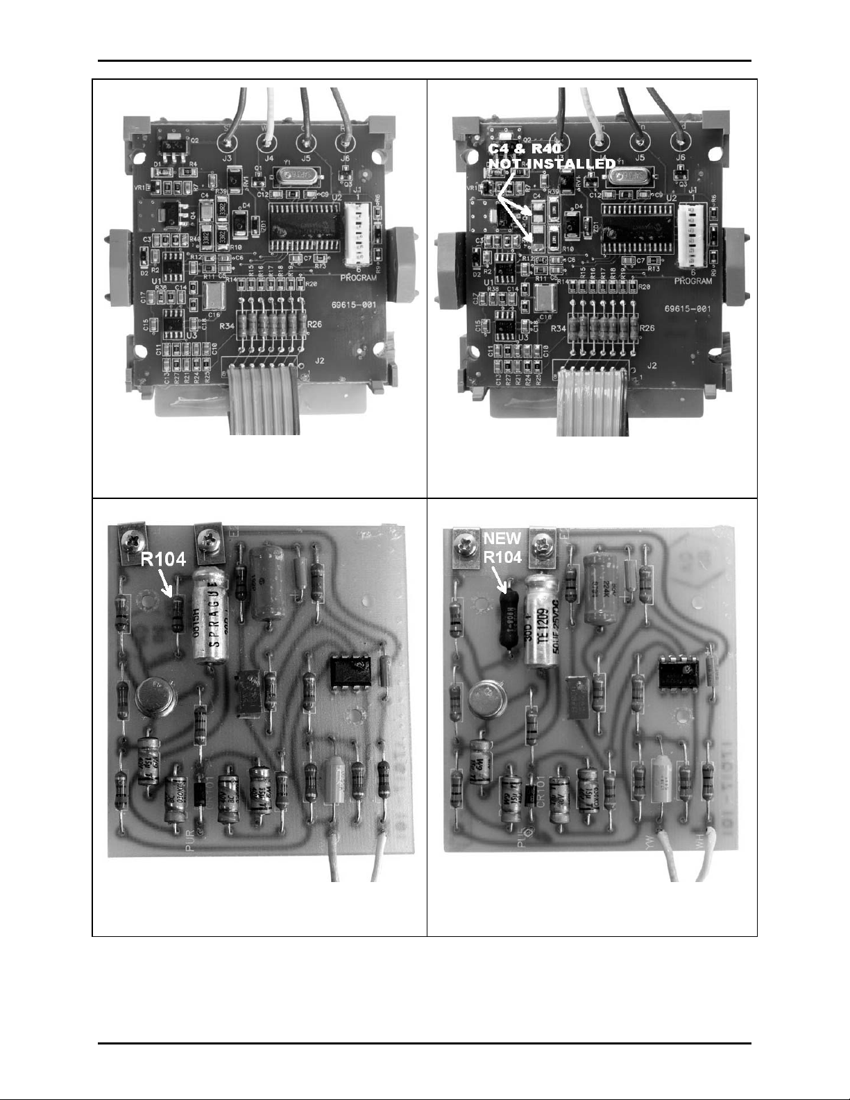
R104 located on 69491-002 PCBA must
approval. See Figures 1, 2, 3 and 4 to give a visual aid to identify and determine if the PCB assemblies
were modified.
GAI-Tronics Corporation 400 E. Wyomissing Ave. Mohnton, PA 19540 USA
610-777-1374 800-492-1212 Fax: 610-796-5954
V
ISIT WWW.GAI-TRONICS.COM FOR PRODUCT LITERATURE AND MANUALS
be a 3-watt wire wound or metal film resistor to maintain MSHA
Page 2
Pub. 42003-218B
Model 12504-010 Keypad Replacement Kit for Model 491-204 Mine Dial Page Phone Page:
2 of 5
Figure 1. Keypad Assembly 69615
BEFORE Modifications
Figure 2. Keypad Assembly 69615
AFTER Modifications
Figure 3. Amplifier PCB Assembly 69491-002
BEFORE R104 Modification
f:\standard ioms - current release\42003 kit manuals\42003-218b.doc
07/09
Figure 4. Amplifier PCB Assembly 69491-002
AFTER R104 Modification
Page 3

Pub. 42003-218B
Model 12504-010 Keypad Replacement Kit for Model 491-204 Mine Dial Page Phone Page:
3 of 5
Procedure
1. DISCONNECT the Mine Dial Page Phone telephone line’s connection from the communication
system.
2. Open the enclosure and disconnect both wires from the positive terminal of the battery.
3. Take note of the positioning of the tie-wraps securing the keypad and wires of the 69491-002 PCB
assemblies. Wires MUST be routed and secured to prevent contact with uninsulated conductors.
Securing of the wiring in the same fashion will be required at completion.
4. Cut each tie-wrap that is holding the keypad wires and the 69491-002 wires to the enclosure wiring
harness. Using the Phillips screwdriver, loosen all screws to remove the keypad wires from the
terminal block TB2 and terminal E1 on the 69491-002. Re-tighten all loosened screws to ensure that
all other wires remain connected to their appropriate locations. See Figure 5.
Figure 5.
69491-002 Modification for Maintaining Intrinsic Safety
(Used in conjunction with keypad PCBA modification)
5. Remove the two 4-40 screws securing the 69491-002 PCBA. Save for re-assembly.
6. On the 69491-002 PCBA, locate R104, which is adjacent to C101 and E2. Refer to Figure 3.
7. De-solder and remove R104 (100-ohm resistor, ½-watt).
8. Install new R104 (100-ohm resistor, 3-watt). Re-solder and trim leads.
9. Re-coat the PCBA around R104’s soldered connections with an approved moisture resistant material.
10. Swing the PCBA out of the way for access to the keypad assembly.
f:\standard ioms - current release\42003 kit manuals\42003-218b.doc
07/09
Page 4

Pub. 42003-218B
Model 12504-010 Keypad Replacement Kit for Model 491-204 Mine Dial Page Phone Page:
Keypad Assembly Replacement
4 of 5
11. Remove the four hex nuts on the rear keypad mounting bracket using the 5/16-inch nut driver. Save
the hex nuts for re-assembly.
12. Lift the rear keypad mounting bracket to expose the keypad assembly. Remove the four ¼-inch hex
standoffs using the ¼-nut driver. Save the hex standoffs for re-assembly.
13. The front keypad mounting panel can now be pulled away from the keypad assembly from the front
of the enclosure.
14. Lift the aluminum keypad spacer off the front keypad mounting panel to expose the keypad seal. See
Figure 6. Save the keypad spacer for re-assembly.
15. Pull the keypad seal off the front keypad mounting panel and dispose of the old seal.
16. Press the new keypad seal into the front keypad mounting panel as shown in Figure 6. Make sure that
each key extrusion of the seal is seating fully into the front keypad mounting panel.
Figure 6.
17. Place the aluminum keypad spacer onto the front keypad mounting bracket to cover the keypad seal.
18. Place the front keypad panel back into the front of the enclosure making sure that the keypad spacer
seats in the opening of the enclosure. Hold the front keypad panel in place and from the inside of the
enclosure, place the new keypad assembly over the studs of the front keypad panel. Use the four ¼inch hex standoffs to secure the keypad assembly to the studs. Tighten the hex standoffs.
19. While holding the front keypad panel and keypad assembly in place, put the rear keypad mounting
bracket over the hex standoffs. Ensure that the four wires from the keypad assembly exit out the top
(speaker side) of the rear keypad mounting bracket. See Figure 5.. Use the four 5/16-inch hex nuts to
secure the rear keypad mounting bracket. Tighten the nuts by using an “x” pattern to ensure uniform
compression of the front keypad panel.
f:\standard ioms - current release\42003 kit manuals\42003-218b.doc
07/09
Page 5

Pub. 42003-218B
Model 12504-010 Keypad Replacement Kit for Model 491-204 Mine Dial Page Phone Page:
5 of 5
20. Re-install the 69491-002 PCBA using the two Phillips head screws.
21. Reconnect the four wires from the keypad assembly as follows:
• Connect white wire to terminal 3 of TB2.
• Connect green wire to terminal 4 of TB2.
• Connect red wire to terminal 5 of TB2.
• Connect slate wire to terminal screw E1 on the 69491-002 PCBA.
22. Re-secure the wiring as noted in Step 3 using supplied tie-wraps. Wires MUST be routed and secured
to prevent contact with uninsulated conductors. Refer to Figure 7 as an example.
Figure 7. Tie-Wrap Location Example
23. Check all work, then reconnect both wires to internal battery’s positive terminal. Test keypad for
proper operation.
f:\standard ioms - current release\42003 kit manuals\42003-218b.doc
07/09
Page 6

Warranty
Equipment. GAI-Tronics warrants for a period of one (1) year from the date of shipment, that any
GAI-Tronics equipment supplied hereunder shall be free of defects in material and workmanship, shall
comply with the then-current product specifications and product literature, and if applicable, shall be fit
for the purpose specified in the agreed-upon quotation or proposal document. If (a) Seller’s goods prove
to be defective in workmanship and/or material under normal and proper usage, or unfit for the purpose
specified and agreed upon, and (b) Buyer’s claim is made within the warranty period set forth above,
Buyer may return such goods to GAI-Tronics’ nearest depot repair facility, freight prepaid, at which time
they will be repaired or replaced, at Seller’s option, without charge to Buyer. Repair or replacement shall
be Buyer’s sole and exclusive remedy. The warranty period on any repaired or replacement equipment
shall be the greater of the ninety (90) day repair warranty or one (1) year from the date the original
equipment was shipped. In no event shall GAI-Tronics warranty obligations with respect to equipment
exceed 100% of the total cost of the equipment supplied hereunder. Buyer may also be entitled to the
manufacturer’s warranty on any third-party goods supplied by GAI-Tronics hereunder. The applicability
of any such third-party warranty will be determined by GAI-Tronics.
Services. Any services GAI-Tronics provides hereunder, whether directly or through subcontractors,
shall be performed in accordance with the standard of care with which such services are normally
provided in the industry. If the services fail to meet the applicable industry standard, GAI-Tronics will
re-perform such services at no cost to buyer to correct said deficiency to Company's satisfaction provided
any and all issues are identified prior to the demobilization of the Contractor’s personnel from the work
site. Re-performance of services shall be Buyer’s sole and exclusive remedy, and in no event shall GAITronics warranty obligations with respect to services exceed 100% of the total cost of the services
provided hereunder.
Warranty Periods. Every claim by Buyer alleging a defect in the goods and/or services provided
hereunder shall be deemed waived unless such claim is made in writing within the applicable warranty
periods as set forth above. Provided, however, that if the defect complained of is latent and not
discoverable within the above warranty periods, every claim arising on account of such latent defect shall
be deemed waived unless it is made in writing within a reasonable time after such latent defect is or
should have been discovered by Buyer.
Limitations / Exclusions. The warranties herein shall not apply to, and GAI-Tronics shall not be
responsible for, any damage to the goods or failure of the services supplied hereunder, to the extent
caused by Buyer’s neglect, failure to follow operational and maintenance procedures provided with the
equipment, or the use of technicians not specifically authorized by GAI-Tronics to maintain or service the
equipment. THE WARRANTIES AND REMEDIES CONTAINED HEREIN ARE IN LIEU OF AND
EXCLUDE ALL OTHER WARRANTIES AND REMEDIES, WHETHER EXPRESS OR IMPLIED BY
OPERATION OF LAW OR OTHERWISE, INCLUDING ANY WARRANTIES OF
MERCHANTABILITY OR FITNESS FOR A PARTICULAR PURPOSE.
Return Policy
If the equipment requires service, contact your Regional Service Center for a return authorization number
(RA#). Equipment should be shipped prepaid to GAI-Tronics with a return authorization number and a
purchase order number. If the equipment is under warranty, repairs or a replacement will be made in
accordance with the warranty policy set forth above. Please include a written explanation of all defects to
assist our technicians in their troubleshooting efforts.
Call 800-492-1212 (inside the USA) or 610-777-1374 (outside the USA) for help identifying the
Regional Service Center closest to you.
(Rev. 10/06)
 Loading...