

Page 1

Pub. 42003- 177A
GAI-TRONICS® CORPORATION
A HUBBELL COMPANY
EZ Page Front Panel Controls
Replacement Kit
Model 12504-009
Confidentiality Notice
This manual is pr ovided s olely as a n op erat ional, installation, and maintenance guide and contains sens itive
bus ines s and t echnic al infor ma tion tha t is confident i al and p roprietary to G AI-Tronics. GAI-Tronics
retains a ll intellectual pr operty and other rights in or to t he inf ormation c ontained herein, and s uch
informa tion may only be used in connection wit h the operation of you r GAI- Tronic s pr oduct or system.
This ma nual may not be disclosed in any form, in whole or in p art, dir ec tly or indirectly, to any t hird pa rty.
General Information
The Model 12504-009 Front Panel Controls Replacement Kit is used with the following EZ Page Intercom
models: GC-AC 1, GC-DC 1, a nd GC-AC 2. This kit incl u des the following components:
Qty Description
1 Knob
1 Fr ont cover s ealing nut f or Lis ten/T alk swit c h
1 Fr ont cover s ealing nut f or sp eaker volume/on- of f switch
1 Wired Li sten/Talk s witch and speaker volume/on-off s witch as sembly
1 Hex nut
1 Anti-rotation ring
Required Tools
•
•
•
•
#2 P hillip s scr ewdr iver
5/8-inch wrench
1/2-inch wrench
.078-inch (5/64 inch) hex allen wrench
GAI-Tronics Corporation P.O. Box 1060, Reading, PA 19607-1060 USA
610-777-1374 800-492-1212 Fax : 610-796-5954
ISIT WWW.GAI-TRONICS.COM FOR PRODUCT LITERATURE AND MANUALS
V
Page 2
Pub. 42003-177A
ODEL 12504-009 EZ PAGE FRONT PANEL CONTROLS REPLACEMENT KIT Page: 2 of 3
M
Installation
WARNING
Disconnect power from the unit before opening or servicing the unit.
Removing the Old Front Panel Controls
1. Disconnec t power to the unit.
2. Using the hex allen wrench, loosen the two screws that sec ure the knob and remove.
3. Using the # 2 screwdriver , remove the s ix fr ont pa nel s c rews t hat secur e the front cover t o the housing.
4. Slowly pull the front cover ass embly f rom the rear housing—do not str es s the attached wires.
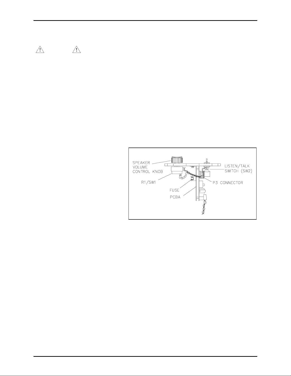
5. Disconnec t the connect or
Note the orientation of the
potentiometer/switch (R1/SW1) and
the toggle swit c h (SW2) for
installat i on of the new contr ols.
6. Using the 5 /8-inc h wrench, remove
and disc ard the sealing nu t holding the
toggle switc h to the front cover .
(P3) from the internal printed circuit board assembly (PCBA).
7. Using the 1 /2-inc h wrench, remove
and disc ard the sealing nu t holding the
potentiometer/switch to the front
cover.
OTE: This will allow sep aration of
N
Figure 1. L oc ation of Controls
the fr ont cover f rom the PCBA’s
heatsink pla te.
8. Discard the wired switch assembly.
Installing the New Front Panel Controls
1. Remove any hardware that might b e p re-attached to the new s peaker volume/on-off s witch; it is not
used in this applic ation.
2. Ensu re tha t the new speaker volume/on- of f switch is tur ned fully count erclockwise t o the off pos ition.
\\s_eng\gtc proddoc s \ s tandard ioms - current release\ 42003 k it m anuals \42003-177a.doc
5/99
Page 3

Pub. 42003-177A
ODEL 12504-009 EZ PAGE FRONT PANEL CONTROLS REPLACEMENT KIT Page: 3 of 3
M
3. Inser t the new sp eaker volume/on- of f switch (R1/SW1) throu gh the heatsink plate and through the
front cover. Ensure that the associated anti-rotat ion pin is proper ly inserted int o the amplifier heatsink
plate’s locking notch and the at tached wires a re positioned towa rds the fuse holder . Refer to F igure 1
and F igure 2.
4. Pla c e the new smaller s ealing nut over
the speaker volume/on- of f switch’s
shaf t and lightly tighten agains t the
front cover.
5. Ensure that the new Listen/Talk
switch’ s sup plied hex nut is screwed
tightly against the s witch body.
6. Install the supplied a nti-rotat ion ring
(locking tab towards heatsink p late)
onto the Li sten/Talk switch’s mounting
threads.
Figure 2. Speaker Volume/On-off Swit c h Assembly
7. Insert the new Listen/Talk switch
thr ough the heatsink plate and front cover.
(Pos ition the bat handle towards t he L
ISTEN position as indic ated on the f ront panel lab el.
8. Pla c e the new sealing nut over t he b at handle and t ighten against the front cover.
9. Tight en the spea ker volume
on/off switch’s sealing nut
aga i nst the f ront cover.
10. R econnect the P3 connector t o
the PCBA.
11. Carefully reinsert the front
panel a ssembly into t he unit’s
housing. Use caution to not
pinch any wires between the
front cover and the housing.
12. Reins tall t he s i x front c over
Figure 3. Listen/Talk Switch Assembly Diagram
screws and tighten sec urely.
13. With the new speaker volume on-off switc h f ully count erclockwise, at tach the new knob. Posit ion the
knob’s white dot adjacent to the off dot on the front p anel lab el and reti ghten both s et screws using the
hex allen wrench.
14. R eapply power a nd c hec k f or proper opera tion.
\\s_eng\gtc proddoc s \ s tandard ioms - current release\ 42003 k it m anuals \42003-177a.doc
5/99
Page 4

Warranty
Equipment. GAI-Tronics warrants for a period of one (1) year from the date of shipment, that any
GAI-Tronics equipment supplied hereunder shall be free of defects in material and workmanship, shall
comply with the then-current product specifications and product literature, and if applicable, shall be fit
for the purpose specified in the agreed-upon quotation or proposal document. If (a) Seller’s goods prove
to be defective in workmanship and/or material under normal and proper usage, or unfit for the purpose
specified and agreed upon, and (b) Buyer’s claim is made within the warranty period set forth above,
Buyer may return such goods to GAI-Tronics’ nearest depot repair facility, freight prepaid, at which time
they will be repaired or replaced, at Seller’s option, without charge to Buyer. Repair or replacement shall
be Buyer’s sole and exclusive remedy. The warranty period on any repaired or replacement equipment
shall be the greater of the ninety (90) day repair warranty or one (1) year from the date the original
equipment was shipped. In no event shall GAI-Tronics warranty obligations with respect to equipment
exceed 100% of the total cost of the equipment supplied hereunder. Buyer may also be entitled to the
manufacturer’s warranty on any third-party goods supplied by GAI-Tronics hereunder. The applicability
of any such third-party warranty will be determined by GAI-Tronics.
Services. Any services GAI-Tronics provides hereunder, whether directly or through subcontractors,
shall be performed in accordance with the standard of care with which such services are normally
provided in the industry. If the services fail to meet the applicable industry standard, GAI-Tronics will
re-perform such services at no cost to buyer to correct said deficiency to Company's satisfaction provided
any and all issues are identified prior to the demobilization of the Contractor’s personnel from the work
site. Re-performance of services shall be Buyer’s sole and exclusive remedy, and in no event shall GAITronics warranty obligations with respect to services exceed 100% of the total cost of the services
provided hereunder.
Warranty Periods. Every claim by Buyer alleging a defect in the goods and/or services provided
hereunder shall be deemed waived unless such claim is made in writing within the applicable warranty
periods as set forth above. Provided, however, that if the defect complained of is latent and not
discoverable within the above warranty periods, every claim arising on account of such latent defect shall
be deemed waived unless it is made in writing within a reasonable time after such latent defect is or
should have been discovered by Buyer.
Limitations / Exclusions. The warranties herein shall not apply to, and GAI-Tronics shall not be
responsible for, any damage to the goods or failure of the services supplied hereunder, to the extent
caused by Buyer’s neglect, failure to follow operational and maintenance procedures provided with the
equipment, or the use of technicians not specifically authorized by GAI-Tronics to maintain or service the
equipment. THE WARRANTIES AND REMEDIES CONTAINED HEREIN ARE IN LIEU OF AND
EXCLUDE ALL OTHER WARRANTIES AND REMEDIES, WHETHER EXPRESS OR IMPLIED BY
OPERATION OF LAW OR OTHERWISE, INCLUDING ANY WARRANTIES OF
MERCHANTABILITY OR FITNESS FOR A PARTICULAR PURPOSE.
Return Policy
If the equipment requires service, contact your Regional Service Center for a return authorization number
(RA#). Equipment should be shipped prepaid to GAI-Tronics with a return authorization number and a
purchase order number. If the equipment is under warranty, repairs or a replacement will be made in
accordance with the warranty policy set forth above. Please include a written explanation of all defects to
assist our technicians in their troubleshooting efforts.
Call 800-492-1212 (inside the USA) or 610-777-1374 (outside the USA) for help identifying the
Regional Service Center closest to you.
(Rev. 10/06)
 Loading...