

Page 1

Pub. 42003-146
GAI-TRONICS® CORPORATION
A HUBBELL COMPANY
Rigcom Harness Replacement Kit
MODELS 12504-007 AND 12504-008
Confidentiality Notice
This manual is pr ovided s olely as a n op erat ional, installation, and maintenance guide and contains sens itive
bus ines s and t echnic al infor ma tion which is conf idential and propriet ary to GAI-Tronics. GAI - Tronic s
retains a ll intellectual pr operty and other rights in or to t he inf ormation c ontained herein, and s uch
informa tion may only be used in connection wit h the operation of you r GAI- Tronic s pr oduct or system.
This ma nual may not be disclosed in any form, in whole or in p art, dir ec tly or indirectly, to any t hird pa rty.
General Information
Model 12504-007 is used on Model MS3987 and MS3990. Model 12504-008 is for use on Model
MS3985, MS3986, and MS3988.
OTE: Installation of this kit mu st be perfor med in a non- haza rdous loc ation, as Rigcom units are
N
Division 1 app roved. The power to the unit mu st be s hut down prior to removing the front cover.
This kit includes the following components:
Description
Qty
1 Bracket/Harness/Switch/Connector Assembly
1 On/Off Volume Knob
1 Push-to-Call Button (for Model 12504-008 only)
12 Bolts
You will need the following tools to install this kit:
• Allen wrench set (0.050-inch for knob)
• Open-end wrench set ( 5/8-inch for new hex nut )
• 2 large spade screwdrivers (for Model 12504-008 only)
GAI-Tronics Corporation P.O. Box 1060, Reading, PA 19607-1060 USA
610-777-1374 800-492-1212 Fax : 610-796-5954
ISIT WWW.GAI-TRONICS.COM FOR PRODUCT LITERATURE AND MANUALS
V
Page 2
Pub. 42003-146
M
ODELS 12504-007 AND 12504-008 RIGCOM HARNESS REPLACEMENT KIT Page: 2 of 3
Installation
Removing the Old Harness Assembly
WARNING
Shut down the power to the unit.
1. Remove the front cover, and caref ully unplu g the harness from the printed circuit board. Discard the
old bolts .
2. Using the appropriat e Allen wrench, loos en t he set screws of the knob on the on/ of f volume switch,
remove and disc ard them (on all models).
3. For Model MS3985, MS3986, and MS3988 only: Using the two spade screwdriver s, p ry the push-to-
call b utton out of s haft, and dis c ard it.
4. On the insi de of the front cover, using the approp riate open-end wrench, loosen the hex nu t(s) holding
the bracket in place.
5. Pull the entire brac ket/harness/switc h/connector assembly st raight out f rom the fr ont cover, and dis c ard
it.
Installing the New Harness Assembly
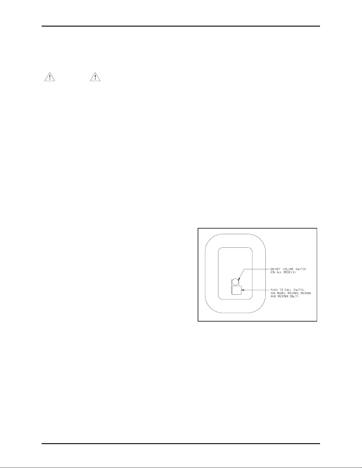
1. Push the entire bracket/ harnes s/switch/connector
assembly straight into the front cover. See Figure 1
for orientation.
2. Tight en the hex nut( s) to the bushing(s) in t he front
5
cover using the
/8-inch open-end wrench. See
Figure 2.
3. Attach a nd tighten the knob onto the on/off volume
switch.
4. For Model MS3985, MS3986, and MS3988 only:
Push the button into the shaft of the push-to-call
switch until the button hits the shaft.
Figure 1. Inside Front Cover
\\s_eng\gtc proddoc s \ s tandard ioms - current release\ 42003 k it m anuals \42003-146.doc
12/94
Page 3

Pub. 42003-146
M
ODELS 12504-007 AND 12504-008 RIGCOM HARNESS REPLACEMENT KIT Page: 3 of 3
5. Plug the connector into t he p rinted circuit boa rd, and atta c h the front cover to the unit with the new
bolts . Make sure that the ribbon cable is not pinched. Tighten the b olts t o 3 0 foot- pounds.
Figure 2. B ottom Edge View
\\s_eng\gtc proddoc s \ s tandard ioms - current release\ 42003 k it m anuals \42003-146.doc
12/94
Page 4

Warranty
Equipment. GAI-Tronics warrants for a period of one (1) year from the date of shipment, that any
GAI-Tronics equipment supplied hereunder shall be free of defects in material and workmanship, shall
comply with the then-current product specifications and product literature, and if applicable, shall be fit
for the purpose specified in the agreed-upon quotation or proposal document. If (a) Seller’s goods prove
to be defective in workmanship and/or material under normal and proper usage, or unfit for the purpose
specified and agreed upon, and (b) Buyer’s claim is made within the warranty period set forth above,
Buyer may return such goods to GAI-Tronics’ nearest depot repair facility, freight prepaid, at which time
they will be repaired or replaced, at Seller’s option, without charge to Buyer. Repair or replacement shall
be Buyer’s sole and exclusive remedy. The warranty period on any repaired or replacement equipment
shall be the greater of the ninety (90) day repair warranty or one (1) year from the date the original
equipment was shipped. In no event shall GAI-Tronics warranty obligations with respect to equipment
exceed 100% of the total cost of the equipment supplied hereunder. Buyer may also be entitled to the
manufacturer’s warranty on any third-party goods supplied by GAI-Tronics hereunder. The applicability
of any such third-party warranty will be determined by GAI-Tronics.
Services. Any services GAI-Tronics provides hereunder, whether directly or through subcontractors,
shall be performed in accordance with the standard of care with which such services are normally
provided in the industry. If the services fail to meet the applicable industry standard, GAI-Tronics will
re-perform such services at no cost to buyer to correct said deficiency to Company's satisfaction provided
any and all issues are identified prior to the demobilization of the Contractor’s personnel from the work
site. Re-performance of services shall be Buyer’s sole and exclusive remedy, and in no event shall GAITronics warranty obligations with respect to services exceed 100% of the total cost of the services
provided hereunder.
Warranty Periods. Every claim by Buyer alleging a defect in the goods and/or services provided
hereunder shall be deemed waived unless such claim is made in writing within the applicable warranty
periods as set forth above. Provided, however, that if the defect complained of is latent and not
discoverable within the above warranty periods, every claim arising on account of such latent defect shall
be deemed waived unless it is made in writing within a reasonable time after such latent defect is or
should have been discovered by Buyer.
Limitations / Exclusions. The warranties herein shall not apply to, and GAI-Tronics shall not be
responsible for, any damage to the goods or failure of the services supplied hereunder, to the extent
caused by Buyer’s neglect, failure to follow operational and maintenance procedures provided with the
equipment, or the use of technicians not specifically authorized by GAI-Tronics to maintain or service the
equipment. THE WARRANTIES AND REMEDIES CONTAINED HEREIN ARE IN LIEU OF AND
EXCLUDE ALL OTHER WARRANTIES AND REMEDIES, WHETHER EXPRESS OR IMPLIED BY
OPERATION OF LAW OR OTHERWISE, INCLUDING ANY WARRANTIES OF
MERCHANTABILITY OR FITNESS FOR A PARTICULAR PURPOSE.
Return Policy
If the equipment requires service, contact your Regional Service Center for a return authorization number
(RA#). Equipment should be shipped prepaid to GAI-Tronics with a return authorization number and a
purchase order number. If the equipment is under warranty, repairs or a replacement will be made in
accordance with the warranty policy set forth above. Please include a written explanation of all defects to
assist our technicians in their troubleshooting efforts.
Call 800-492-1212 (inside the USA) or 610-777-1374 (outside the USA) for help identifying the
Regional Service Center closest to you.
(Rev. 10/06)
 Loading...