

Page 1

Pub. 42004-674L2H
GAI-TRONICS® CORPORATION
A HUBBELL COMPANY
NOVA Public Address Systems
S.M.A.R.T. Modules
T ABLE OF C ONTENTS
Confidentiality Notice .....................................................................................................................1
General Information .......................................................................................................................1
Product Overview ................................................................................................................................... 1
System Requirements and Limitations ................................................................................................. 1
Features and Functions .......................................................................................................................... 2
Description of the NOVA S.M.A.R.T Components.............................................................................. 2
System Block Diagram ........................................................................................................................... 3
Locating NOVA S.M.A.R.T Modules in the Central Cabinet ............................................................ 4
Central Processor Unit ........................................................................................................................... 4
Line Integrity Module (LIM) ..........................................................................................................4
Description ............................................................................................................................................... 4
Controls ................................................................................................................................................................. 5
Set-Up ....................................................................................................................................................... 5
Operation ................................................................................................................................................. 6
Normal Mode ........................................................................................................................................................ 6
Program Mode ...................................................................................................................................................... 7
Line Integrity Module Specifications .................................................................................................. 10
Fuse Replacement ................................................................................................................................. 10
Test Tone Generator Module ........................................................................................................11
Description ............................................................................................................................................. 11
Set-Up ..................................................................................................................................................... 11
Setting the Individual Tone Output Level ........................................................................................................... 12
Test Tone Generator Specifications .................................................................................................... 12
Fuse Replacement ................................................................................................................................. 12
ALC Control Module ....................................................................................................................13
Description ............................................................................................................................................. 13
Installation ............................................................................................................................................. 13
Setup Procedure .................................................................................................................................... 14
GAI-Tronics Corporation 400 E. Wyomissing Ave. Mohnton, PA 19540 USA
610-777-1374 800-492-1212 Fax: 610-796-5954
V
ISIT WWW.GAI-TRONICS.COM FOR PRODUCT LITERATURE AND MANUALS
Page 2

Table of Contents Pub. 42004-674L2H
NOVA PUBLIC ADDRESS SYSTEMS - S.M.A.R.T. MODULES
System Optimization ........................................................................................................................................... 15
Paging Level Update ........................................................................................................................................... 15
Setting the Kick-up Ratio .................................................................................................................................... 16
Setting the Page Min. Level ................................................................................................................................ 16
ALC Control Module Specifications ................................................................................................... 17
Fuse Replacement ................................................................................................................................. 17
ALC Remote Module .....................................................................................................................18
Description ............................................................................................................................................. 18
Set-Up ..................................................................................................................................................... 19
ALC Remote Module Specifications ................................................................................................... 20
Speaker Master Module ................................................................................................................21
Description ............................................................................................................................................. 21
Set-Up ..................................................................................................................................................... 22
Speaker Master Module Specifications ............................................................................................... 22
Speaker Remote Module ...............................................................................................................23
Description ............................................................................................................................................. 23
Set Up ..................................................................................................................................................... 24
Speaker Remote Module Specifications .............................................................................................. 24
ii
Page 3

Pub. 42004-674L2H
GAI-TRONICS® CORPORATION
A HUBBELL COMPANY
NOVA Public Address Systems
S.M.A.R.T. Modules
Confidential ity Notice
This manual is provided solely as an operational, installation, and maintenance guide and contains sensitive
business and technical information that is confidential and proprietary to GAI-Tronics. GAI-Tronics
retains all intellectual property and other rights in or to the information contained herein, and such
information may only be used in connection with the operation of your GAI-Tronics product or system.
This manual may not be disclosed in any form, in whole or in part, directly or indirectly, to any third party.
General Information
Product Overview
The NOVA S.M.A.R.T. Modules are a collection of function-specific modules that perform various fault
detection tasks in extended range communication systems. It is an alarm and an alarm supervision system
that is transparently incorporated within a public address/paging system, such as the NOVA Public
Address System. The modules are designed with a common serial interface to a GAI-Tronics central
processing unit. The CPU forwards the system indications to an operator paging console typically located
in a control room or office.
The NOVA S.M.A.R.T. Modules are capable of monitoring many components of any type of wired audio
paging system for health status and report faults both locally through logic closure outputs, and remotely
via serial data link.
The low-level audio paths through a system are monitored by the use of sub-audible tones mixed into
inputs and detected on outputs.
The high-level power audio connections are monitored for integrity by measuring loop resistance and
ground fault leakage.
Individual loudspeaker integrity can be checked using the speaker remote modules that sample
speaker audio current. When commanded, these modules report their health status to a central
location via RF data modem over the audio distribution lines of a central amplifier system.
The speaker remote modules are also capable of changing individual loudspeaker power levels on
command from a central location. This can be done on a system-wide or individual speaker basis.
The range of adjustment is in steps from off/mute to full power.
System Requirements and Limitations
The NOVA S.M.A.R.T. Modules are either housed in a central cabinet or installed in field locations, and
each typically requires an uninterruptible 24 V dc power source.
A complete system can support up to 120 zones, each containing as many speakers as the power amplifier
can support.
GAI-Tronics Corporation 400 E. Wyomissing Ave. Mohnton, PA 19540 USA
610-777-1374 800-492-1212 Fax: 610-796-5954
V
ISIT WWW.GAI-TRONICS.COM FOR PRODUCT LITERATURE AND MANUALS
Page 4

Pub. 42004-674L2H
PUBLIC ADDRESS SYSTEMS - S.M.A.R.T. MODULES PAGE 2 of 24
NOVA
Features and Functions
Mixed analog and digital technology eliminates complex technical set-up
SMT components
Standard industrial mounting
Description of the NOVA S.M.A.R.T Components
The NOVA System can combine some or all of the modules described below with a common serial
interface to the GAI-Tronics NOVA Central Processor Unit. The Line Integrity Module (LIM) and the
Automatic Level Control (ALC) modules are able to perform on a stand-alone basis and interface alarm
statuses via solid-state relay closure outputs.
The following is a list of the NOVA S.M.A.R.T. modules. Some or all the modules may be purchased
depending on specific customer requirements.
Line Integrity Module (12389-001) consists of the LIM Speaker Line Termination PCBA
(69389-010) and LIM Controller PCBA (69389-020) connected by a ribbon cable. It monitors the
line resistance as a means of detecting and reporting line faults. The module injects a selectable (10,
20, 30, 40, or 60 mA) current on each speaker line. During initial set-up, a baseline resistance is
established and the LIM reports changes of more than 20%, which would indicate an open, short, or
leakage to ground has occurred. The LIM can also be used in other systems where line resistance
may be measured as a means of health-check.
Test Tone Generator Module (12393-101) provides low frequency test tones used to health-check
the low-level audio paths and power amplifiers. This module is used in conjunction with the Speaker
Master Module as a power source for remote speaker modules.
ALC Control Module (included with 12395-001) provides a means to automatically adjust the
volume of voice pages and alarm tones in response to varying levels of ambient noise in a specific
area. In a typical system, the ALC Control Module is located in-line between the low-level audio
path switching equipment and the regional power amplifier. The control module provides line power
to the ALC Remote Module, which is connected to a dummy speaker or other microphone device for
sensing ambient noise.
ALC Remote Module (included with 12395-001) samples the ambient noise within a paging zone
and provides necessary information to the ALC Control Module to adjust the volume of voice pages
and alarm tones in a specific area.
Speaker Master Module (69403-101) controls power to the remote and transmits the power level tap
commands to the Speaker Remote Modules and receives the speaker coil health check status from the
Speaker Remote Modules.
Speaker Remote Modules (13317-001 and 13317-002) receives power level tap commands to
control speaker volume and health checks the speaker coil.
Each module, and its function, set-up, and adjustment is described in detail in this manual. Refer to the
block diagram on page 3.
The Model 12604-014 Replacement Fuse Kit is available for all of the NOVA S.M.A.R.T. Modules. It
contains ten of each of the required sizes.
f:\standard ioms - current release\42004 instr. manuals\42004-674l2h.doc
12/13
Page 5
Pub. 42004-674L2H
PUBLIC ADDRESS SYSTEMS - S.M.A.R.T. MODULES PAGE 3 of 24
NOVA
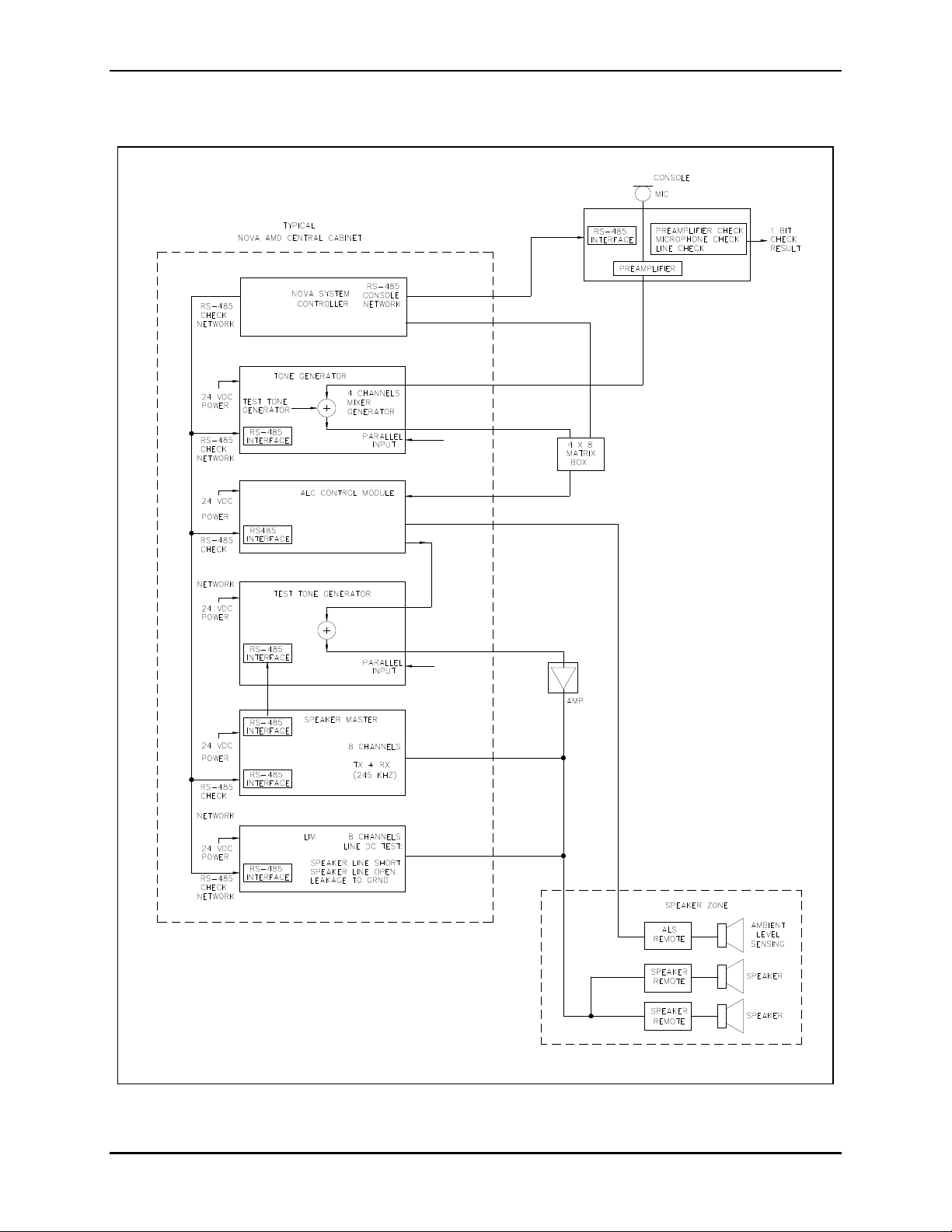
System Block Diagram
Figure 1. Block Diagram
f:\standard ioms - current release\42004 instr. manuals\42004-674l2h.doc
12/13
Page 6

Pub. 42004-674L2H
PUBLIC ADDRESS SYSTEMS - S.M.A.R.T. MODULES PAGE 4 of 24
NOVA
Locating NOVA S.M.A.R.T Modules in the Central Cabinet
The NOVA S.M.A.R.T. Modules must be housed in a cabinet or enclosure located in an environmentallycontrolled area. In larger installations, an auxiliary panel devoted to some of the modules is desirable.
The optimum configuration is to have the installed modules horizontally in “snap-track” style mountings
that directly face the technician. When mounted in this manner, all board-mounted controls and
connectors are easily accessible.
Central Processor Unit
The NOVA Central Processor Unit controls larger, more complex systems, and is usually housed in the
central cabinet along with other system equipment.
The CPU polls the various NOVA S.M.A.R.T Modules via a common RS-485 serial bus and sends
commands, as needed, to monitor the system health and supervise the ALC modules. The system CPU is
responsible for setting up both manual and automatically-initiated voice paging and the monitoring of
various alarm inputs.
Line Integrity Module (LIM)
Description
The GTC 12389-001 LIM Module consists of two PCBAs, the GTC 69389-01x LIM Speaker Line
Termination PCBA and the GTC 69389-02x LIM Controller PCBA, connected by a ribbon cable. The
LIM can monitor the speaker wire line integrity by measuring the resistance of up to eight zones or
speaker loops and reports faults on the line. When attached to a remote loudspeaker or ac power line, the
LIM breaks the dc loop continuity and isolates the gap with a large capacitance. The LIM monitors the dc
continuity of the loop by applying a selectable calibrated dc current across the isolating capacitors and
monitoring the dc portion of the loop for changes of more than 20% in loop resistance.
Furthermore, a test for leakage to earth is conducted by applying a dc voltage between the line loop and
earth ground and monitoring the current drain on the applied potential to determine acceptable limits of
leakage to earth. The application of excitation current and the measurement of the result are under the
control of a microcontroller and are multiplexed over eight lines per module.
In a complex alarm management system, the LIM communicates the alarm status with the system CPU
via RS-485. Under RS-485 (advanced) control the test interval is under the supervision of a system
central processor unit. This control can include modification and subsequent overwrite of an individual
line mean value in the form of positive or negative “tweaks.”
The LIM is also able to stand alone in a simple system and output alarm status on eight line-unique,
optically-isolated alarm closures. The supervised or stand-alone mode selection is via the address jumper
field, JU2 through JU5 on the LIM Controller PCBA.
f:\standard ioms - current release\42004 instr. manuals\42004-674l2h.doc
12/13
Page 7

Pub. 42004-674L2H
PUBLIC ADDRESS SYSTEMS - S.M.A.R.T. MODULES PAGE 5 of 24
NOVA
Controls
The LIM module contains two push buttons, ANALYZE/STORE and TEST/STEP, and a rotary line-
select switch. The button functions for the Normal mode are ANALYZE and TEST, and are
STORE and
STEP in the program mode.
In the Normal mode, pressing the ANALYZE button causes any fault condition on the line currently
selected by the rotary switch to be displayed on the fault-descriptive LEDs:
Line SHORT
Line OPEN
LEAK
Set-Up
Install the LIM modules in the central cabinet using the standard “snap-track” style mounting. Ensure the
push button controls and the LED indicators are easily accessible to the operator or technician for
diagnostic tools. Refer to the system block diagram on page 3.
WARNING
Never separate or rejoin the PCBAs at J2 and J3
with the ribbon cable while the power is applied!
1. Install the ribbon connector between J2 on the Speaker Line Termination PCBA and J3 on the LIM
Controller PCBA.
2. Connect the audio power lines from the amplifiers and speakers to the appropriate terminal blocks on
the Speaker Line Termination PCBA.
3. Make the 24 V dc power connections to TB20 on the LIM Controller PCBA.
4. Install jumper JU1 on the LIM Controller PCBA and perform the speaker line selection programming.
Refer to the “Program Mode” section below for instructions. Remove the jumper when the
programming is complete.
f:\standard ioms - current release\42004 instr. manuals\42004-674l2h.doc
12/13
Page 8

Pub. 42004-674L2H
PUBLIC ADDRESS SYSTEMS - S.M.A.R.T. MODULES PAGE 6 of 24
NOVA
Set the LIM for either internal or external control. Internal or external control mode is determined by the
setting of the address jumpers JU2, JU3, JU4, and JU5. These are connected in binary fashion and
determine the serial network address of each individual LIM.
OTE: These settings cannot be duplicated when external control is used for multiple LIMs.
N
Table 1.
Network
Address JU2 JU3 JU4 JU5
0
1
2
3
4
5
6
7
X
X
X X
X
X X
X X
X X X
Network
Address
8
9
10
11
12
13
14
15
(Free-run Mode)
JU2 JU3 JU4 JU5
X
X X
X X
X X X
X X
X X X
X X X
X X X X
X indicates the jumper is installed.
5. If applicable, connect RS-485 for external communication with CPU using the 8-pin modular
connectors J4 and J1 on the LIM controller PCBA.
Operation
The LIM has two operational modes: the Normal (measurement) mode and the Programming mode. The
Programming mode is selected by inserting a shorting jumper, JU1. Removing the jumper returns the
LIM to the Normal mode.
Normal Mode
In the Normal mode, at a pre-programmed time interval, the microprocessor selects one of the eight
monitored lines at a time, applying a specific dc current through the line dc loop, and measures the loop
voltage. If the measured voltage falls within predetermined limits (as defined in the Program mode), the
line loop resistance is determined to be within tolerance.
If not, an alarm is initiated as a line-unique logic closure. An LED indication is physically linked to the
alarm closure. If the loop voltage is too high, (above tolerance) the line is assumed to be wholly or in
part, “open.” If the loop voltage is too low the line is assumed to be wholly or in part, “shorted.”
In either case, the out-of-tolerance condition is retained in RAM for further processing as described
below. The leakage test is then applied to the line. An out-of-tolerance failure is indicated by a logic
output from a leakage comparator. The fault determination is a hardware function.
f:\standard ioms - current release\42004 instr. manuals\42004-674l2h.doc
12/13
Page 9

Pub. 42004-674L2H
PUBLIC ADDRESS SYSTEMS - S.M.A.R.T. MODULES PAGE 7 of 24
NOVA
A leakage fault also generates an alarm and this condition is also stored in RAM. Fault testing continues
on all lines regardless of previously existing alarm conditions. This is in order to determine a return-tonormal status. A return-to-normal condition causes an existing alarm to be rescinded (removal of alarm
closure). Long-term fault history and trend information is the responsibility of the system CPU and is not
stored within this module.
There are two functions available in the Normal mode: a lamp test, and a display of the fault condition
that caused test failure for any of the eight speaker lines.
Lamp Test
Press and hold both the TEST and ANALYZE push buttons for 3 seconds. All eleven LEDs (three fault-
descriptive LEDs and eight line-alarm LEDs) illuminate and remain so as long as the buttons are
depressed.
OTE: Be aware that the eight line-alarm relay outputs are activated during the LED test.
N
Fault Condition Display
Use this feature to learn what specific measurement (line open, line shorted, or line leakage) failed for a
given line during testing so that appropriate repair action may be taken.
1. Select a speaker line with the rotary line-select switch.
2. Press and hold the ANALYZE push button.
3. Wait 3 seconds
for the fault indication to be displayed on the summary LEDs. All LEDs are off if the
line passed the most recent testing. The fault indication continues to be displayed as long as the
ANALYZE button is pressed.
Program Mode
The Program mode is used to add or delete speaker lines, to set a mean voltage value and corresponding
limits to be used for line testing for each installed speaker line, and to set the time interval for free-run
mode line testing.
The two push-button switches, STORE and STEP, and the rotary line-select switch are active in the
Program mode. While in the Program mode, the microprocessor connects the current generator to the line
selected by the rotary switch.
f:\standard ioms - current release\42004 instr. manuals\42004-674l2h.doc
12/13
Page 10

Pub. 42004-674L2H
PUBLIC ADDRESS SYSTEMS - S.M.A.R.T. MODULES PAGE 8 of 24
NOVA
Set Up
1. Enter the Program mode by inserting a shorting clip across the program mode jumper (JU1).
2. Select Active Speaker or Zone Lines: Select one of the lines on the rotary line-select switch, S1
using a small flat-bladed screwdriver. Positions 0 through 7 refer to lines or channels 1 through 8,
respectively.
3. Press the STEP button momentarily, causing the current generator to step to the next value (in
circular fashion) and to display the current value on one of the following fault-descriptive LED
settings:
No LED = 0 mA
(The selected speaker line is considered inactive. Set all unconnected lines to 0 to prevent the
reporting of erroneous fault conditions. No tests will be performed on these lines.)
SHORT LED = 10 mA
OPEN LED = 20 mA
LEAK LED = 30 mA
OTE: When JU6, a current-doubling jumper is installed, the current values are approximately
N
doubled to 20 mA, 40 mA, and 60 mA for the three active index values.
4. Select a current value that will result in a displayed voltage value near mid-range. A stored value too
high or too low may result in the calculated limits exceeding the design limits.
Press the STORE button momentarily to begin the measurement cycle. During this time, the three
fault LEDs flash sequentially, and then count down in binary. The resultant 8-bit voltage value is
displayed in binary format on the eight line-unique alarm LEDs (and corresponding output closures).
N
OTE: Line 1 Alarm is LSB and Line 8 Alarm is MSB.
5. Set Mean Voltage and Line Testing Limits: Press the STORE button continuously for more than 3
seconds to store the selected current value and the measured result in NVRAM for the line that is
currently selected using the rotary switch. The measured result is used as the mean value and faults
are calculated as deviations greater than +\−20% of the stored value. The three fault-descriptive
LEDs will flash three times to indicate that the value has been stored.
f:\standard ioms - current release\42004 instr. manuals\42004-674l2h.doc
12/13
Page 11

Pub. 42004-674L2H
PUBLIC ADDRESS SYSTEMS - S.M.A.R.T. MODULES PAGE 9 of 24
NOVA
6. Set Line Test Interval: When all the lines have been programmed, and the results have been stored,
select the interval for the stand-alone self-commanded test. To do this, move the rotary line-select
switch to the time value according to Table 2 below.
Table 2.
Time Switch Position
15 minutes 8
30 minutes 9
1 hour A
2 hours B
6 hours C
8 hours D
12 hours E
24 hours F
7. Then press and hold the button for 3 seconds
now stored. N
OTE: The factory-default test interval is 1 hour.
8. Remove the JU1 programming jumper.
until the fault LEDs begin flashing. The test interval is
f:\standard ioms - current release\42004 instr. manuals\42004-674l2h.doc
12/13
Page 12

Pub. 42004-674L2H
PUBLIC ADDRESS SYSTEMS - S.M.A.R.T. MODULES PAGE 10 of 24
NOVA
Line Integrity Module Specifications
Power input ....................................................................................... 24 V dc +/−20% @ 200 mA maximum
Physical size of each PCBA .............................................................................. 4 W 15 L 4 D inches, and
3 W 15 L 4 D inches
Operating environment ..................................................... 0 C to 50 C @ 95 % humidity, non-condensing
Inputs ....................................................... Eight 100 V, 70 V, or 50 V audio line pass-through connections:
1200 watts maximum/channel
7.5 mm Euro-style wire-capture terminal strip accommodates wire sizes up to No. 10 AWG
System connection .................................... RS-485 I/O non-isolated, for external communication with CPU
Connection is via 8-pin modular jack
Two parallel connectors are provided
Two technical control switches for programming and line-fault determination
Outputs ...................................................................... Eight isolated alarm closures 220 V ac, off-withstand,
120 mA ac, 33 ohms, on
Connection method: ................................................................. 5 mm Euro-style wire capture terminal strips
Visual indication ..................................................... 11 LEDs for programming and line-fault determination
Line test output ................................................................................10 mA, or 20 mA, or 30 mA dc current;
or, 20 mA or 40 mA, or 60 mA dc current into 100 volt line
selected in firmware programming for line loop resistance test
Line test resistance range ........................................................................................................... 1 to 40 ohms
Fuse Replacement
CAUTION
For continued safe operation, replace fuses with the same type:
F1 is a Bussman GDC 500 mA fuse.
F2 and F3 are Bussman GDC 200 mA fuses.
N
OTE: The Model 12604-014 Replacement Fuse Kit is available for all of the S.M.A.R.T. Modules. It
contains 10 of each of the required sizes.
f:\standard ioms - current release\42004 instr. manuals\42004-674l2h.doc
12/13
Page 13

Pub. 42004-674L2H
PUBLIC ADDRESS SYSTEMS - S.M.A.R.T. MODULES PAGE 11 of 24
NOVA
T est T one Generator Module
Description
The GTC 69393-101 Test Tone Generator Module is a key component of an S.M.A.R.T. Module system.
It provides the tone signal generation and a method to mix the tone signal into the required audio
pathways. It provides a tone used as a generator for an inaudible source of power to the Speaker Remote
Modules, when used.
The Test Tone Generator module contains the following controls and indicators:
Table 3. Test Tone Generator Controls and Indicators
Control or
Indicator
Communication
Function
This LED lights when the module is communicating with the Speaker Master.
Indicator LED
P5 This jumper puts the Test Tone Generator into the Diagnostic mode.
P6 This jumper resets the Test Tone Generator.
J1 This jumper adds a terminating resistor to the RS-485 line.
P1 through P4 These jumpers connect a 600-ohm terminating resistor to the input of each channel.
CH1-R21,
These individual potentiometers are used to set the individual tone output levels.
CH2-R28,
CH3-R39,
CH4-R44
Set-Up
Refer to the board layout diagram.
1. Make the low level audio input and output connections for up to four channels at TB1, TB2, TB3, and
TB4 as follows:
Table 4.
Channel 1 Channel 2 Channel 3 Channel 4
TB1-1 Shield GND TB2-1 Shield GND TB3-1 Shield GND TB4-1 Shield GND
TB1-2 Line output TB2-2 Line output TB3-2 Line output TB4-2 Line output
TB1-3 Line output TB2-3 Line output TB3-3 Line output TB4-3 Line output
TB1-4 Line input TB2-4 Line input TB3-4 Line input TB4-4 Line input
TB1-5 Line input TB2-5 Line input TB3-5 Line input TB4-5 Line input
TB1-6 Shield GND TB2-6 Shield GND TB3-6 Shield GND TB4-6 Shield GND
2. Make the 24 V dc power connections at TB5. The polarity is noted on the board.
f:\standard ioms - current release\42004 instr. manuals\42004-674l2h.doc
12/13
Page 14

Pub. 42004-674L2H
PUBLIC ADDRESS SYSTEMS - S.M.A.R.T. MODULES PAGE 12 of 24
NOVA
Setting the Individual Tone Output Level
3. Connect only the field wiring for the channel which is having its output level adjusted. Disconnect
the other terminal blocks.
4. Set the Test Tone Generator into the Diagnostic mode by putting jumper P5 onto positions 2 and 3.
This will turn on the 35 Hz output continuously.
5. Adjust the pot for the channel being set so that the level of the 35 Hz tone at the farthest remote is
50 Vrms.
6. Repeat steps 3 and 5 for all channels in use, then put P5 onto positions 1 and 2 taking the Test Tone
Generator out of the Diagnostic mode.
Test Tone Generator Specifications
Power input ....................................................................................... 24 V dc +/−20% @ 150 mA maximum
Physical size .............................................................................................. 4.00 W 6.50 L 1.250 D inches
Operating environment ................................................... 0 C to 50 C @ 95 % humidity (non-condensing)
Inputs ..................................................... Four channels, low level (0 dBm) balanced audio line connections
Input impedance ............................................................................................ 600 ohms or 100 k selectable
Connection method ................................................................... 5-mm Euro-style wire-capture terminal strip
System connection .................................... RS-485 I/O non-isolated, for external communication with CPU
Connection is via 8-pin modular jack
Output ............................................................. Four channels, low level (0 dBm) balanced audio line driver
Output impedance ............................................................................................................................ 100 ohms
Connection method ................................................................... 5-mm Euro-style wire-capture terminal strip
Tone output level .................................................................................... Variable from +4 dBm to −46 dBm
Fuse Replacement
CAUTION
For continued safe operation, replace fuses with the same type:
F1 is a Bussman GDC 500 mA fuse.
f:\standard ioms - current release\42004 instr. manuals\42004-674l2h.doc
12/13
Page 15

Pub. 42004-674L2H
PUBLIC ADDRESS SYSTEMS - S.M.A.R.T. MODULES PAGE 13 of 24
NOVA
ALC Control Mo dule
Description
The GTC 12395-001 ALC Control Module Kit, includes one ALC Control Module and one ALC Remote
Module. This provides a means to automatically adjust the volume of voice pages and alarm tones in
response to varying levels of ambient noise in a specific area. In a typical system, the ALC Control
Module is located in-line between the low-level audio path switching equipment and the regional power
amplifier. The master module provides line power to the ALC Remote Module, which is connected to a
dummy speaker or other microphone device for sensing ambient noise.
The ALC Remote Module is located within the paging zone. The ambient noise sample is transmitted to
the ALC Control Module to be measured and used to modify the level of the audio to the paging
amplifier.
The control module is equipped with control buttons and indicator lights used during initial set-up of the
system paging volume levels. The internal software allows set up of the paging levels without being
affected by the current ambient noise levels. As fail-safe measures, the audio path through the module is
bypassed with a mechanical relay if input power is lost.
If desired, a person using headphones or an external speaker can monitor sounds in a remote location
using the master module’s auxiliary amplifier output.
Installation
NOTE: The ALC Remote Module must be installed and set up before the master can be programmed and
made operational.
The ALC Control Module is physically located in the central cabinet using the standard “snap-trak” style
mounting.
1. Mount the unit in the rear of the cabinet.
2. Connect the sensing line pair from the ALC Remote Module to TB4-1 and TB4-2. TB4-3 is for a
shield, where used.
WARNING
3. Connect input from audio path switching to TB2-1 and TB2-2. A shield on TB2-3 should only
connected on the ALC Control Module.
4. Connect the output line pair to the power amplifier at TB1-1 and TB1-2. A shield on TB1-3 should
only be connected on the ALC Control Module.
5. Connect the paging logic input (where applicable) to TB3-1 and TB3-2.
Observe dc polarity.
be
6. Connect the emergency logic input to TB5-1 and TB5-2.
7. Connect RS485 serial bus where applicable. Two connectors, J1 and J2, are provided for a
daisy-chain connection.
8. Connect 24 V dc input power:
TB6-1: Positive TB6-2: Negative (return) TB6-3: Cabinet frame
f:\standard ioms - current release\42004 instr. manuals\42004-674l2h.doc
12/13
Page 16

Pub. 42004-674L2H
PUBLIC ADDRESS SYSTEMS - S.M.A.R.T. MODULES PAGE 14 of 24
NOVA
Setup Procedure
As a prerequisite, matrix (audio steering chassis) output for this channel is set to 0 dBm (full system
output level).
1. Press the I
initializes the LVL mode. The A
NITIALIZE button for 3 seconds. The microcontroller sets the attenuator to −21 dB and auto-
CKNOWLEDGE LED flashes for 1 second, and the POWER LED
begins to flash.
2. Station a partner with a two-way radio at the zone to which this device is associated. Initiate paging,
and with guidance from your partner, adjust the volume level of the page to accommodate the current
ambient noise level by pressing the UP or DOWN buttons. (The microcontroller is in the LVL
mode.) The Bar Graph LEDs indicate the paging and noise levels coming back from the Remote
Module.
3. After the paging and adjusting process is finished, press the C
CKNOWLEDGE LED flashes for one second. This causes the microcontroller to begin a 10-second
A
ALIBRATE button for 3 seconds.
measurement cycle of the ambient noise at the remote site. (Microcontroller measures and averages
noise until the 10-second timer counts down, causes the A
CKNOWLEDGE LED to flash, saves the
result in RAM, and waits for Save command.) Note: If the ambient noise level changes significantly
during this calibration period, the noise level will no longer match the adjusted paging volume and the
adjusted paging volume and adjustment procedure must be repeated.
4. After 10 seconds, the A
CKNOWLEDGE LED begins flashing signifying that it has completed analysis
of the ambient noise. The Bar Graph LEDs indicate the level of noise from the paging zone. This
visual result may be compared with that which was observed during the test paging.
5. Press S
AVE to store the paging volume setting along with the companion noise level.
(Microprocessor stores attenuator reference level and the noise reference level in NVRAM). The
CKNOWLEDGE LED and the POWER LED cease flashing (Normal mode).
A
6. Test the system by introducing more noise into the controlled zone, and listening to additional paging
over the increased noise. If the paging volume level is not sufficient to overcome the increased noise,
refer to System Optimization below.
f:\standard ioms - current release\42004 instr. manuals\42004-674l2h.doc
12/13
Page 17

Pub. 42004-674L2H
PUBLIC ADDRESS SYSTEMS - S.M.A.R.T. MODULES PAGE 15 of 24
NOVA
System Optimization
After the paging attenuator reference level and noise reference level have been stored in memory, they are
used as a starting point whenever a power-down/power-up has occurred. From this point the
microprocessor measures the “new” current noise level, sums it with the stored noise reference and uses
the difference to add to or subtract from the reference paging attenuator value. This result, always in
RAM is the “current attenuator value.” This process continues indefinitely with exception to the actual
paging period, which is detected by the logic closure input or command via RS-485.
The relationship between noise level and attenuator setting is linear at normally 1:1 ratio. As ambient
noise increases in 3 dB steps, the paging audio level is raised by an equivalent amount in 3 dB steps.
However, the ratio between the change in the noise level and the change in the paging level can be
modified to a larger ratio by adding additional steps of paging volume for every step of increase in
ambient noise. The ratio then would be 1:1+N where N is the number of additional steps required.
For example, if N = 1 and noise goes up by 3 dB, the paging volume goes up 6 dB. This ratio is referred
to as the kick-up ratio and the N number as the kick-up value. This feature is most useful when the
predominant ambient noise in the zone is full-spectrum in nature and tends to mask paging audio more
quickly that single-tone (whine or hum) type noise. Examples of full spectrum noise would be the sound
of gravel running down a chute or the hiss of a large volume of air pressure being released.
If the paging level simply needs to be further adjusted (tweaked) without changing the kick-up ratio, then
perform the paging level update procedure described below.
The minimum paging attenuation may also be established in order to maintain a minimum area coverage
even under completely quiet ambient conditions. This is referred to as Page Min. and is expressed in 3
dB SPL steps.
OTE: If at any time the system is in any of the Programming modes and no button activity has been
N
detected for 15 minutes, the system automatically returns to the Normal Operating mode using the
operating values that were previously in the memory.
Paging Level Update
1. Ensure that the system is in the Normal Operating mode: POWER LED ON – steady.
2. Press the L
OWER LED begins to flash on and off. (The C is in LVL mode.) Press the UP or DOWN buttons
P
EVEL button for 3 seconds. The ACKNOWLEDGE LED must flash for one second, and the
to modify the paging level.
3. Press the L
stores only the new attenuator reference level in NVRAM.) The P
EVEL and SAVE buttons together for 3 seconds to save the new paging level. (The C
OWER LED ceases flashing
indicating the return to the Normal mode.
4. The Bar Graph LEDs continue to indicate the audio level coming from the ALC Remote Module for
approximately 5 minutes after a level-save operation and then extinguish. If at any time after the
time-out period you wish to view the level indication, press the L
EVEL button momentarily (less than
3 seconds). The Bar Graph LEDs again indicates the level for 5 minutes.
f:\standard ioms - current release\42004 instr. manuals\42004-674l2h.doc
12/13
Page 18

Pub. 42004-674L2H
PUBLIC ADDRESS SYSTEMS - S.M.A.R.T. MODULES PAGE 16 of 24
NOVA
Setting the Kick-up Ratio
1. The system must be in the Normal Operating mode: POWER LED on – Steady.
2. Press the U
P and DOWN buttons together for 3 seconds. The ACKNOWLEDGE LED must flash for one
second and the Bar Graph LEDs 1, 2, 3, 6, and 7 light steadily and the last three (10, 11, 12) indicate
the kick-up value. This is indicated by:
LED 10 for N = 1
LED 11 for N = 2
LED 12 for N = 3
If none of these three are on, the kick-up value is 0 (ratio 1:1). The C turns LEDs 1, 2, 3, 6 and 7
on; and turns LED 4, 5, 8, 9 off, and puts the kick-up value in LEDs 10 through 12.
3. To change the kick-up value, press the U
4. To save the new value in memory, press the S
P or DOWN buttons.
AVE button. The Bar Graph LEDs extinguish and the
system returns to the Normal Operating mode.
5. To view the level indication of the noise audio coming back from the Remote Module, press the
EVEL button momentarily (less than 3 seconds). The Bar Graph LEDs indicate the level for 5
L
minutes.
Setting the Page Min. Level
1. The system must be in the Normal Operating mode: POWER LED on – steady.
2. Press the L
EVEL and DOWN buttons together for 3 seconds. The ACKNOWLEDGE LED flashes for
one second and the Bar Graph LEDs 1 and 12 flash. The default Page Min. level of −33 dB is
displayed on LED 10 (−21 dB) down to LED 3 (−42 dB).
3. To change the Page Min. level, press the U
press the D
OWN button until LEDs 3 through 10 are all off.
P or DOWN buttons. To turn off the minimum page level,
4. To save the new value in memory, press the S
system returns to the Normal Operating mode.
AVE button. The Bar Graph LEDs extinguish and the
f:\standard ioms - current release\42004 instr. manuals\42004-674l2h.doc
12/13
Page 19

Pub. 42004-674L2H
PUBLIC ADDRESS SYSTEMS - S.M.A.R.T. MODULES PAGE 17 of 24
NOVA
ALC Control Module Specifications
Power input ...................................................................................... 24 V dc +/−20% @ 350 mA maximum
Physical size ................................................................................................... 4.0 W 13.5 L 3.0 D inches
Operating environment .................................................... 0º C to 50 C @ 95% humidity (non-condensing)
Paging input impedance ..................................................................... 100 k, or jumper-selected 600 ohms
Paging audio I/O range .................................................................................................... −40 dBm to 0 dBm
Paging adjustment range ....................................................................................... −3 dB to -30 dB minimum
Emergency paging level .................................... Direct wire connection from input to output, no attenuation
Paging audio S/N ratio .................................................................................. 45 dB minimum, ref. to 0 dBm
Paging audio distortion .....................................................................................................Less than 1% THD
Output impedance .................................................................................... 100 ohms, electronically balanced
Monitor amp output ...................................................... 250 W maximum into a standard 30-ohm headset
Fuse Replacement
CAUTION
For continued safe operation, replace fuses with the same type:
F1 is a Bussman GMC 600 mA fuse.
N
OTE: The Model 12604-014 Replacement Fuse Kit is available for all of the S.M.A.R.T. Modules. It
contains ten of each of the required sizes.
f:\standard ioms - current release\42004 instr. manuals\42004-674l2h.doc
12/13
Page 20

Pub. 42004-674L2H
PUBLIC ADDRESS SYSTEMS - S.M.A.R.T. MODULES PAGE 18 of 24
NOVA
ALC R emote Module
Description
The ALC Remote Module, included in the GTC 12395-001 ALC Control Kit, is housed in a separate
enclosure in the logical subzone to be monitored.
The location of the mounting holes on the 4.0 4.0-inch board are shown in Figure 2 below.
Figure 2. Mounting Dimensions for the ALC Remote Module PCBA
The dummy speaker or dynamic mic must be positioned close by to accurately sample the ambient noise
in the area. The remote is line-powered by the ALC Control Module, so an additional power source is
unnecessary. The wire line to the master must be of sufficient size to prevent significant resistance losses
to the phantom dc power. See the wire-size chart below.
Guideline:
Total line resistance including both conductors must not exceed 20 ohms (10 ohm/wire)
Table 5. Wire Size Chart
Wire-run, Feet from
Master to Remote
Recommended
Minimum Wire Size
1000 No. 20 AWG
2000 No. 16 AWG
3000 No. 14 AWG
f:\standard ioms - current release\42004 instr. manuals\42004-674l2h.doc
12/13
Page 21

Pub. 42004-674L2H
PUBLIC ADDRESS SYSTEMS - S.M.A.R.T. MODULES PAGE 19 of 24
NOVA
Set-Up
Install the enclosure for ALC Remote Module as close to the remote sensing speaker or microphone as
possible. Ensure the conduit entrances are sealed for protection from dust and moisture.
1. Connect the two wires from the remote sensing speaker/mic to TB402-1 and TB402-2. TB402-3 is a
shield connection. If a shield is used, it must be connected only to TB402-3 and not to the conduit.
2. Connect the two lines from the ALC Control Module.
Observe polarity
TB401-1 is dc positive. TB401-2 is negative.
3. Adjust the amplifier gain settings. The remote sensing amplifier provides ten gain levels for
matching various sensing devices. The gain levels are listed in the table below. There are two high
frequency filter caps that can be switched in to provide noise bandwidth limiting.
. These carry the phantom line dc power and must be connected properly.
Table 6.
Module
Gain
45
50
55
60
65
70
75
80
92
97
−1 −2 −3 −4 −5 −6
ON
ON ON
ON
ON ON
ON
ON ON
ON
ON ON
ON
ON ON
SWA Sections
Table 7.
Bandwidth* SWA-7 SW-8
1 ON
2 ON
3 ON ON
*The high frequency bandwidth limiting function increases when used with higher gain.
f:\standard ioms - current release\42004 instr. manuals\42004-674l2h.doc
12/13
Page 22

Pub. 42004-674L2H
PUBLIC ADDRESS SYSTEMS - S.M.A.R.T. MODULES PAGE 20 of 24
NOVA
4. The table below lists available paging speakers that can be used as a “dummy speaker” pick-up
device and the initial gain settings. Usable audio frequency response is also listed. It may be
necessary to further adjust the gain to match noise sensitivity.
Table 8. Initial Gain Settings
Manufacturer Speaker Model Gain Usable AFR
GAI-Tronics 13350 60 dB Wide
DNH HP15-8 45 dB Less than 2.5 kHz
DNH B406-8-W 60 dB Wide
DNH B650-8 60 dB Wide
GAI-Tronics 13314-002 (driver) 45 dB Less than 2.5 kHz
GAI-Tronics 13310-101 (driver) 45 dB Less than 2.5 kHz
ALC Remote Module Specifications
Phantom power input ........................................ (phantom from master) 20 to 30 V dc @ 35 mA maximum
Physical size .................................................................................................. 4.0 W 4.0 L ~2.0 D inches
Operating environment ............................................... −40º C to 80 C @ 95% humidity (non-condensing)
Remote input .............................................................................. Dedicated 8-ohm speaker or dynamic mic,
Input is transformer-isolated and protected against directly-applied signals up to 120 V ac
f:\standard ioms - current release\42004 instr. manuals\42004-674l2h.doc
12/13
Page 23

Pub. 42004-674L2H
PUBLIC ADDRESS SYSTEMS - S.M.A.R.T. MODULES PAGE 21 of 24
NOVA
Speak er Master Module
Description
In normal operation, the GTC 69403-101 Speaker Master Module communicates with the CPU via an
RS-485 connection. It transmits output speaker power level tap and page group control commands via an
RF modem to the Speaker Remote Modules in order to control broadcast volume levels and locations. It
receives acknowledgment messages and speaker integrity messages from the remote modules.
The module has four channels, and transmits and receives RF communication at 245 kHz. Each channel
is connected to the speaker line output of an associated paging zone power amplifier. The module also
controls an associated Test Tone Generator Module via a dedicated RS-485 connection. This tone
generator provides 35 Hz power (through the zone power amp) to the Speaker Remote Modules.
Figure 3. Speaker Master Module
f:\standard ioms - current release\42004 instr. manuals\42004-674l2h.doc
12/13
Page 24

Pub. 42004-674L2H
PUBLIC ADDRESS SYSTEMS - S.M.A.R.T. MODULES PAGE 22 of 24
NOVA
Set-Up
1. Connect RS-485 for external communication with the CPU using the 8-pin modular connector(s)
J301 and J302.
2. Make the 24 V dc power connection at P1.
3. Make the RS-485 control connection to the associated test tone generator module at J401.
4. Make the speaker zone audio line (parallel) connections at TB1–TB4.
5. Apply power to the central amplifier, Speaker Master Module and Test Tone Generator.
6. Set up the Test Tone Generator using the instructions in the “Test Tone Generator” section.
7. Configure the Speaker Master Module with a laptop computer equipped with an RS-485 port and
cable attached to J301 or J302 using a proprietary software package. Refer to the instructions that
accompany the software for further information.
8. Using the laptop and proprietary software, verify the Speaker Master Module turns on the Test Tone
Generator for each channel in use and can poll one Speaker Remote Module on each channel in use.
Speaker Master Module Specifications
Power input ....................................................................................... 24 V dc +/−20% @ 100 mA maximum
Physical size ................................................................................................ 4.00 W 7.50 L 1.25 D inches
Operating environment ................................................... 0 C to 50 C @ 95 % humidity (non-condensing)
f:\standard ioms - current release\42004 instr. manuals\42004-674l2h.doc
12/13
Page 25

Pub. 42004-674L2H
PUBLIC ADDRESS SYSTEMS - S.M.A.R.T. MODULES PAGE 23 of 24
NOVA
Speak er Remote Module
Description
The GTC 13317-001 (8-ohm, 25-watt) and 13317-002 (16-ohm, 30-watt) Speaker Remote Modules are
installed with each speaker that is to be remotely adjusted and monitored. The Speaker Remote Module
receives speaker tap control commands from the Speaker Master Module via an RF modem.
Refer to Figure 4 for overall dimensions and mounting details.
Figure 4. Speaker Remote Module
f:\standard ioms - current release\42004 instr. manuals\42004-674l2h.doc
12/13
Page 26

Pub. 42004-674L2H
PUBLIC ADDRESS SYSTEMS - S.M.A.R.T. MODULES PAGE 24 of 24
NOVA
It is powered by a 35-Hz signal and monitors the current into the associated loudspeaker in order to
perform a health check on the speaker coil. The transmission of acknowledgments and data, as required,
back to the Speaker Master Module is performed only on command from the master.
The Speaker Remote Module provides both high and low power settings. The high/low power setting is
selected using the jumper P6. Based on the jumper setting, the following tap settings can be configured
with a proprietary software package:
13317-001 (8-ohm, 25-watt)
High – 25 W, 12.5 W, 6.25 W
Low – 6 W, 3 W, 1.5 W
13317-002 (16-ohm, 30-watt)
High – 30 W, 15 W, 7.5 W
Low – 6 W, 3 W, 1.5 W
The software also provides the assignment of four page groups out of a possible 255 for systems that
utilize subzoning.
Set Up
The speaker remote module is housed in a separate enclosure at the speaker location. Follow the
manufacturer’s instructions for mounting this enclosure. Fit the board into the enclosure using the
appropriate size stand-offs.
1. The line input is connected to terminals TB1-1 and TB1-2.
2. The output to the loudspeaker is connected at terminals TB3-1 and TB3-2.
Initial programming is “flash” type for the internal microprocessor. Adjustments can be made with a
laptop computer using the P5 field data input connector and the proprietary software package. Refer to
the instructions that accompany the software for further information.
Speaker Remote Module Specifications
Power input ............................ Paging audio for speaker health-check, 35-Hz tone for data communications
Physical size .............................................................................................. 4.50 L 3.90 H ~2.80 D inches
Operating environment ................................................. −40º C to 70º C @ 95% humidity (non-condensing)
f:\standard ioms - current release\42004 instr. manuals\42004-674l2h.doc
12/13
Page 27

Warranty
Equipment. GAI-Tronics warrants for a period of one (1) year from the date of shipment, that any
GAI-Tronics equipment supplied hereunder shall be free of defects in material and workmanship, shall
comply with the then-current product specifications and product literature, and if applicable, shall be fit
for the purpose specified in the agreed-upon quotation or proposal document. If (a) Seller’s goods prove
to be defective in workmanship and/or material under normal and proper usage, or unfit for the purpose
specified and agreed upon, and (b) Buyer’s claim is made within the warranty period set forth above,
Buyer may return such goods to GAI-Tronics’ nearest depot repair facility, freight prepaid, at which time
they will be repaired or replaced, at Seller’s option, without charge to Buyer. Repair or replacement shall
be Buyer’s sole and exclusive remedy. The warranty period on any repaired or replacement equipment
shall be the greater of the ninety (90) day repair warranty or one (1) year from the date the original
equipment was shipped. In no event shall GAI-Tronics warranty obligations with respect to equipment
exceed 100% of the total cost of the equipment supplied hereunder. Buyer may also be entitled to the
manufacturer’s warranty on any third-party goods supplied by GAI-Tronics hereunder. The applicability
of any such third-party warranty will be determined by GAI-Tronics.
Services. Any services GAI-Tronics provides hereunder, whether directly or through subcontractors,
shall be performed in accordance with the standard of care with which such services are normally
provided in the industry. If the services fail to meet the applicable industry standard, GAI-Tronics will
re-perform such services at no cost to buyer to correct said deficiency to Company's satisfaction provided
any and all issues are identified prior to the demobilization of the Contractor’s personnel from the work
site. Re-performance of services shall be Buyer’s sole and exclusive remedy, and in no event shall GAITronics warranty obligations with respect to services exceed 100% of the total cost of the services
provided hereunder.
Warranty Periods. Every claim by Buyer alleging a defect in the goods and/or services provided
hereunder shall be deemed waived unless such claim is made in writing within the applicable warranty
periods as set forth above. Provided, however, that if the defect complained of is latent and not
discoverable within the above warranty periods, every claim arising on account of such latent defect shall
be deemed waived unless it is made in writing within a reasonable time after such latent defect is or
should have been discovered by Buyer.
Limitations / Exclusions. The warranties herein shall not apply to, and GAI-Tronics shall not be
responsible for, any damage to the goods or failure of the services supplied hereunder, to the extent
caused by Buyer’s neglect, failure to follow operational and maintenance procedures provided with the
equipment, or the use of technicians not specifically authorized by GAI-Tronics to maintain or service the
equipment. THE WARRANTIES AND REMEDIES CONTAINED HEREIN ARE IN LIEU OF AND
EXCLUDE ALL OTHER WARRANTIES AND REMEDIES, WHETHER EXPRESS OR IMPLIED BY
OPERATION OF LAW OR OTHERWISE, INCLUDING ANY WARRANTIES OF
MERCHANTABILITY OR FITNESS FOR A PARTICULAR PURPOSE.
Return Policy
If the equipment requires service, contact your Regional Service Center for a return authorization number
(RA#). Equipment should be shipped prepaid to GAI-Tronics with a return authorization number and a
purchase order number. If the equipment is under warranty, repairs or a replacement will be made in
accordance with the warranty policy set forth above. Please include a written explanation of all defects to
assist our technicians in their troubleshooting efforts.
Call 800-492-1212 (inside the USA) or 610-777-1374 (outside the USA) for help identifying the
Regional Service Center closest to you.
(Rev. 10/06)
 Loading...