

Page 1
Pub. 42003-109E
GAI-TRONICS® CORPORATION
A HUBBELL COMPANY
Volume Level Control Receiver Assembly
Replacement Kit
MODEL 12250-001
Confidentiality Notice
This manual is pr ovided s olely as a n op erat ional, installation, and maintenance guide and contains sens itive
bus ines s and t echnic al infor ma tion tha t is confident i al and p roprietary to G AI-Tronics. GAI-Tronics
retains a ll intellectual pr operty and other rights in or to t he inf ormation c ontained herein, and s uch
informa tion may only be used in connection wit h the operation of you r GAI- Tronic s pr oduct or system.
This ma nual may not be disclosed in any form, in whole or in p art, dir ec tly or indirectly, to any t hird pa rty.
General Information
This kit is for use on t he following handset/spea ker amplifiers and speaker amplifiers with t he
corresponding p rinted circuit boa rd assembly (P CBA):
120 V AC
Amplifier
Model No.
651-001 69650-101 701-103 69701-102
701-101 69701-101, 69701-007 701-203 69701-005
701-102 69701-101, 69701-007 701-207 69701-011
701-201 69701-004, 69701-007 701-307 69701-015
701-202 69701-004, 69701-007 713-102 69713-202
701-204 69701-006, 69701-009 723-003 69723-202
701-205 69701-006, 69701-009 751-002 69701-012
701-302 69701-008
701-304 69701-014
723-001 69723-101, 69723-201
751-001 69701-010
PCBA No.
24 V DC
Amplifiers
Model No.
PCBA No.
GAI-Tronics Corporation P.O. Box 1060, Reading, PA 19607-1060 USA
610-777-1374 800-492-1212 Fax : 610-796-5954
ISIT WWW.GAI-TRONICS.COM FOR PRODUCT LITERATURE AND MANUALS
V
Page 2

Pub. 42003-109E
M
ODEL 12250-001 VOLUME LEVEL CONTROL RECEIVER ASSEMBLY REPLACEMENT KIT Page: 2 of 7
Notes:
1. This volume level control ( VL C) kit can be us ed on older GAI-T ronics amplifiers (not listed); however,
it is not recommended. Amplifier models not inc l u ded on t he lis t on pa ge 1 have been obsolet e s inc e
the 1987-1989 time period, and replacement parts for them are available on a limited basis. If the VLC
is to b e installed in a station with an older amplifier, r ep lace amplifier with a listed model (possi b ly
switching amplifiers from a loc ation that does not r equire a VL C and has a newer , list ed amplifier).
2. FM and C SA ap prova ls are nullified with t he addition of VLC.
This kit includes the following components:
Qty
Description
1 Volume Level Control Receiver Assembly
2 Screw, 6-32 x ¼-inch PHMS
2 Resistor, ¼ watt, 5%
1 Templa te (for loc ating drilling holes)
1 Tie Wrap
1 Label,
24 VDC Only
: All items conta i ned in t his kit may not b e required in all installat ions.
Note
Installation
Preparation of VLC Board (24 V DC Applications Only)
Models 701-103, 701-203, 701-207, 701-307, 713-102, 723-003 and 751-002
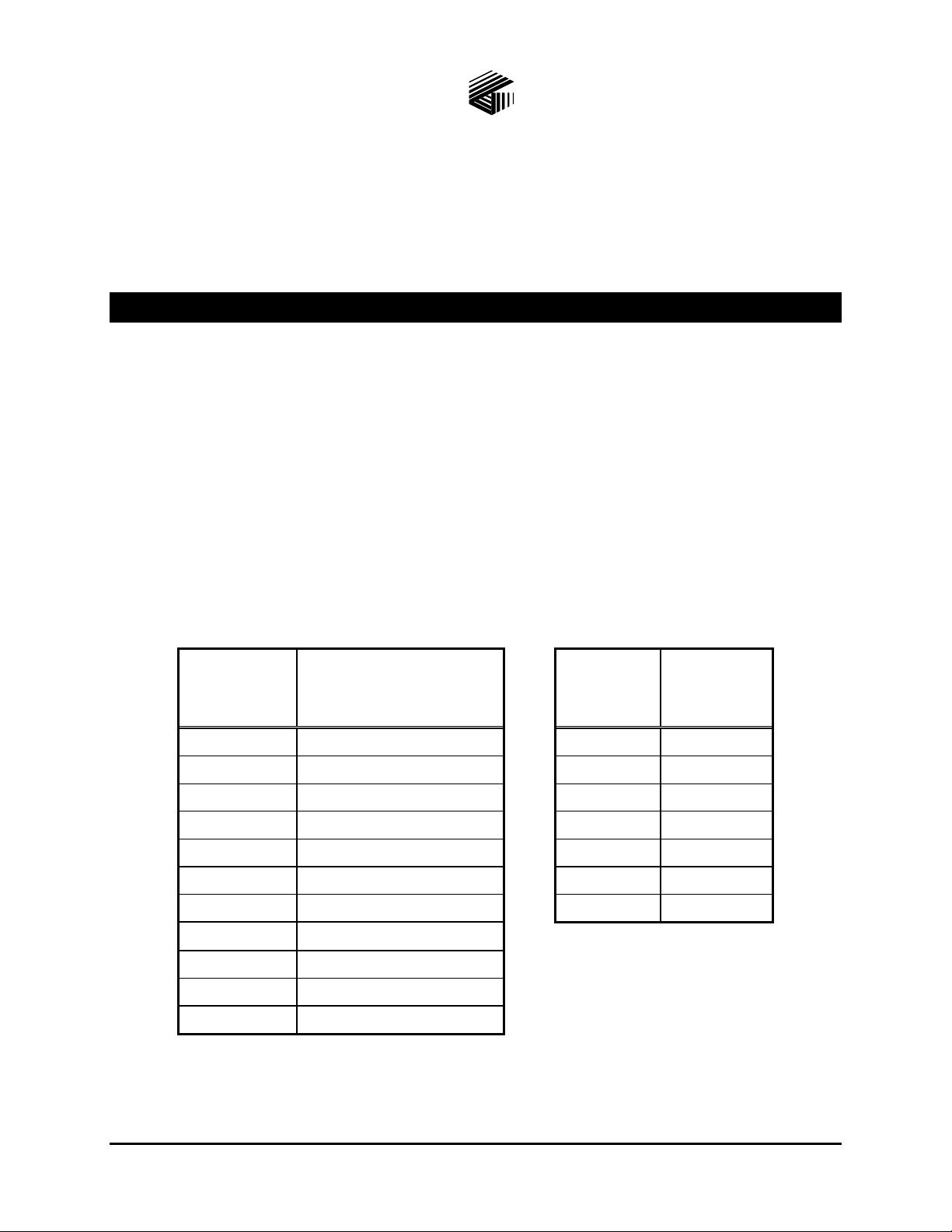
1. Remove the hardware securing Q101 (tabbed transistor) to the VLC PCBA mounting bracket. See
Figure 1. Make note of the placement of the Q101 mounting hardware pieces so that it is re-assembled
correctly later.
2. Remove the 3 screws securing the PCBA to the mounting bracket.
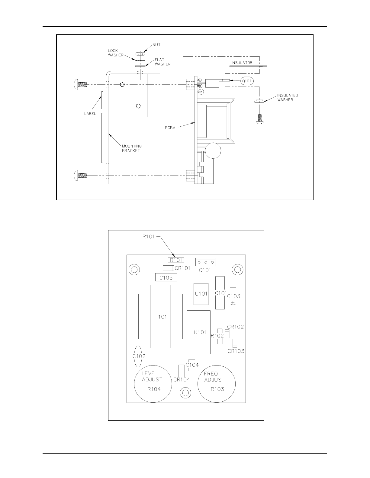
3. Replace R101 by de-soldering and removing the old resistor. Insert the 6,200 ohm, ¼ watt, 5%
(blue-red-red- gold) resistor p rovided in this kit into the PCBA, and res older it. See Figure 2.
4. Trim the resistor leads on the solder side to avoid possible shorts after re-assembly.
5. Reinstall the VLC PCBA ont o the mounting bracket with 3 screws previously removed.
6. Reinstall Q101’s mounting hardware taking extra care to ensure the correct orientation of the insulator
to avoid a pos sible short of the transistor c ollector tab to the gr ound. S ee F igure 1.
7. Place the
24 VDC ONLY la bel provided in this kit on the mount ing plat e.
\\s_eng\gtc proddoc s \ s tandard ioms - current release\ 42003 k it m anuals \42003-109e.doc
10/02
Page 3
Pub. 42003-109E
M
ODEL 12250-001 VOLUME LEVEL CONTROL RECEIVER ASSEMBLY REPLACEMENT KIT Page: 3 of 7
Figure 1. VLC Assembly
Figure 2. VLC PCBA Component Loc ation
\\s_eng\gtc proddoc s \ s tandard ioms - current release\ 42003 k it m anuals \42003-109e.doc
10/02
Page 4

Pub. 42003-109E
M
ODEL 12250-001 VOLUME LEVEL CONTROL RECEIVER ASSEMBLY REPLACEMENT KIT Page: 4 of 7
Disassemb ly
1. Loosen the 4 front panel screws, and remove the amplif ier fr om t he enclos ure.
2. Loosen the 4 sc rews on the s i de, and s lide t he chass is to remove the front panel. I f the unit does not
conta i n a handset, immediat ely s et the front pa nel aside.
3. If the unit c ontains a handset, disconnect the wires at t he p rinted circuit boa rd assembly (P CBA), and
set t he front p anel aside. Note the wire color and location prior to removal to a llow f or eas ier reassembly.
Note
: Skip Step 4 if the amplifier does not have a c hassis-mounted t rans f ormer.
4. Place the c hass is on the bench with the connector t oward you. Di sconnect the transf ormer by removing
the 2 mount ing screws. Disconnect the 6-pin Molex connector from the PC BA, and s et it a side.
: On Model 701-204, 701-205, and 701-304 also disconnect t he t wo 6-pin M olex c onnectors
Note
from the PCBAs assoc iated with the aux iliary handset jack. Make note of the connector(s) p osition
when removing them, as the connector ( s) will be reins talled la ter. Remember to save the parts .
CAUTION
Removal of the PCBA befor e dr illing is advisable.
5. Loosen the 2 screws holding the amphenol connector to the chassi s. If the amplifier c ontains a small
PCBA (Model 69072-001) mounted to the chassis, detach this by removing the 4 screws, and set them
aside. Note the b oard’ s orientation.
6. Using pliers, press the plastic standoffs through the back of the chassis to remove the PCBA. Set the
PCB A aside. B e careful not to brea k the standoffs when p ushing them through.
7. Turn the chas sis over . With the connector opening at the top of the chassis, place the template along
the right edge of the chassi s as shown on the diagram. Refer to Figu re 3 below.
5
8. With the templat e in p lace, carefu lly c ent er punch the holes. Drill two
/32-inch holes, and debu rr the
opposite side.
Figure 3. Template 25354
\\s_eng\gtc proddoc s \ s tandard ioms - current release\ 42003 k it m anuals \42003-109e.doc
10/02
Page 5

Pub. 42003-109E
M
ODEL 12250-001 VOLUME LEVEL CONTROL RECEIVER ASSEMBLY REPLACEMENT KIT Page: 5 of 7
9. Orient the P CBA with t he connector at t he t op.
: Step 1 0 is applica ble for models t hat ha ve R14 ins talled in the off - hook detection circuit ry. See
Note
applicab le models a nd ass oc iated boards in Figur es 4A, 4B, and 4 C for listing.
10. Replace R14 by de-soldering and removing the old resistor (10,000 ohm, ¼ watt, 5%
[brown-black-orange-gold]). Insert the 4,700 ohm, ¼ watt, 5% (yellow-violet-red-gold] resistor
provided in t his kit into the PCBA, and re-solder it. Trim the resist or leads to avoid possible s horts
after re-assembly. See Figure 4.
11. De-solder and remove the W-3 jump er (0-ohm r es istor ) between E25 and E26. S ee a pplica ble model in
Figure 4.
12. Remove solder f rom the following pads wit h a solder remover tool. If a s older remover tool is not
available, use a solder wick to remove the solder: E23, E24, E25, E26, E28, and E31.
Note
: P1 c onnections do not requir e removing the solder. Heat the pin with the soldering iron, a nd
push the wire in.
Re-assemb ly
13. Wire connections from the VLC are t o be soldered to the PCBA. See applica ble model and PC boar d
in Figure 4.
Note
: “E” loc ations may vary slightly f rom what is shown in Fi gu re 2; however , the connections
re main the same.
Black E28
Red E31
Brown E24
White E26
Green E23
Yellow E25
Red/Blu e P1 ( L 1) Refer to applica ble model and PC boar d in Figure 4.
Blue/Red P1 (L2) Refer to applicable model and PC board in Figure 4.
14. Replace the PCBA by inserting the amphenol connector in the chas sis opening and pr es sing it int o
place. Push the s tandof f s through the chass is, and reti ghten the 2 screws holding the amphenol
connector to the cha ssis. Reinstall t he Model 69072-001 PCBA, if applicable.
15. Connect the pur ple wire fr om the front p anel to E7 on the PCBA, if applica ble. On P CBA as semblies
69701-008, 69701-014, and 69701-015, connect one of the magneti c reed hookswitc h wires from the
front panel to E7 on t he PCBA. Connect t he ot her wire t o E 5 on the PCBA. On PCBA assemblies,
(new Model 69701-007, 69701-008, 69701-009, 69701-011, 69701-014, and 69701-015) ensure that
the clip is bent inward to the board to prevent shorting any adja c ent component.
16. Pla c e the VLC mount i ng f lange between the chass is and t he PCBA, and align it with t he holes. Insert
two 6-32 x ¼ -inch screws, an d tighten th em. Rec h eck the purpl e wi re a t E7 of the PCBA fo r cl ear ance
from adjacent component s, if applicable.
\\s_eng\gtc proddoc s \ s tandard ioms - current release\ 42003 k it m anuals \42003-109e.doc
10/02
Page 6

Pub. 42003-109E
M
ODEL 12250-001 VOLUME LEVEL CONTROL RECEIVER ASSEMBLY REPLACEMENT KIT Page: 6 of 7
Figure 4. W iring Details
\\s_eng\gtc proddoc s \ s tandard ioms - current release\ 42003 k it m anuals \42003-109e.doc
10/02
Page 7

Pub. 42003-109E
M
ODEL 12250-001 VOLUME LEVEL CONTROL RECEIVER ASSEMBLY REPLACEMENT KIT Page: 7 of 7
17. If the u nit has a hands et, pick up t he front p anel, and position it so the remaining handset wires ca n be
hooked up to the PCB A. For ease of insta llation, the handset wires are color coded as follows:
White See note bel ow.
Black E2
Green E3
Red E4
Yellow E5
Blue E6
: For the Model 69701-006 PCBA, connect the white wire t o E 18. For t he Model 69701-009 and
Note
69701-014 PCBA, connect the white wir e t o E41. For all others, c onnec t the white wir e to E1.
18. If the unit is a Model 701-204, 701-205, or 701-304, reconnect the two 6- pin Molex connectors from
the front panel to the PCBA at J102 of the amplifier and to J103 of the Model 69072-001 PCBA.
19. Reinsta ll the transformer on the chass i s using the 2 screws r emoved previously. The blu e and br own
wires on the transformer shou ld be facing up, or the chassi s will not close.
20. Rec onnect the 6-pin Molex connec tor t o the PCB A.
21. Dress the VLC wires, and secure them with the tie wrap included in this kit.
: Ensure tha t the coil cord and t he purp le wire (if applicable) or hookswitch wires are routed away
Note
from T1, which is located in the upper left corner of the P CBA on ac-powered models only.
22. Mount the front panel to the chassis, and tighten the 4 screws.
23. P lug the amplifi er into t h e enclos ure, a n d tighten th e 4 sc rews .
Notes
:
1. Speaker adjus tment for normal operat ion remains under the nameplate on the front panel a nd does not
change wit h the additi on of the VLC. The s peaker adjustment for the VLC is fac tory s et and can be
var i ed by adjus ting the level potentiometer on the VLC ass embly.
2. When an alarm is broadcast from Model TS958 and is accompanied by a VLC (50 kHz) signal, it
triggers the volume on the Page/Party® VLC amplifier to increase. GAI-Tronics Model 800 and
1200 Series cone speaker assemblies are normally used for indoor a pplica tions wit h low ambient noise,
such as off i c es , cor ridor s, a nd c ontrol rooms. These speakers have a ma nual, wall-mounted remote
volume level control.
When these speakers a re po wered b y a P age/Party® VLC ampli fier , a n d
the volume level is manually
turned down using t he wall-mounted r emote volume level control, t he s ignal that increases the volume
on the VLC amplifier will not bypass the manual setting. These s peakers remain “turned down,”
regardless of the outp ut signal of the amplifier, and the alarm broadcast level does NOT incr ease on the
cone speaker assemblies.
The Model 800 and 1200 Series speakers can be used in emergency notification systems; however, we
suggest tha t the cus tomer NOT inst all the wall- mounted remote volume level control f or this type of
application.
3. DO NOT READJUST the frequency potentiometer on the VLC ass embly.
\\s_eng\gtc proddoc s \ s tandard ioms - current release\ 42003 k it m anuals \42003-109e.doc
10/02
Page 8

Warranty
Equipment. GAI-Tronics warrants for a period of one (1) year from the date of shipment, that any
GAI-Tronics equipment supplied hereunder shall be free of defects in material and workmanship, shall
comply with the then-current product specifications and product literature, and if applicable, shall be fit
for the purpose specified in the agreed-upon quotation or proposal document. If (a) Seller’s goods prove
to be defective in workmanship and/or material under normal and proper usage, or unfit for the purpose
specified and agreed upon, and (b) Buyer’s claim is made within the warranty period set forth above,
Buyer may return such goods to GAI-Tronics’ nearest depot repair facility, freight prepaid, at which time
they will be repaired or replaced, at Seller’s option, without charge to Buyer. Repair or replacement shall
be Buyer’s sole and exclusive remedy. The warranty period on any repaired or replacement equipment
shall be the greater of the ninety (90) day repair warranty or one (1) year from the date the original
equipment was shipped. In no event shall GAI-Tronics warranty obligations with respect to equipment
exceed 100% of the total cost of the equipment supplied hereunder. Buyer may also be entitled to the
manufacturer’s warranty on any third-party goods supplied by GAI-Tronics hereunder. The applicability
of any such third-party warranty will be determined by GAI-Tronics.
Services. Any services GAI-Tronics provides hereunder, whether directly or through subcontractors,
shall be performed in accordance with the standard of care with which such services are normally
provided in the industry. If the services fail to meet the applicable industry standard, GAI-Tronics will
re-perform such services at no cost to buyer to correct said deficiency to Company's satisfaction provided
any and all issues are identified prior to the demobilization of the Contractor’s personnel from the work
site. Re-performance of services shall be Buyer’s sole and exclusive remedy, and in no event shall GAITronics warranty obligations with respect to services exceed 100% of the total cost of the services
provided hereunder.
Warranty Periods. Every claim by Buyer alleging a defect in the goods and/or services provided
hereunder shall be deemed waived unless such claim is made in writing within the applicable warranty
periods as set forth above. Provided, however, that if the defect complained of is latent and not
discoverable within the above warranty periods, every claim arising on account of such latent defect shall
be deemed waived unless it is made in writing within a reasonable time after such latent defect is or
should have been discovered by Buyer.
Limitations / Exclusions. The warranties herein shall not apply to, and GAI-Tronics shall not be
responsible for, any damage to the goods or failure of the services supplied hereunder, to the extent
caused by Buyer’s neglect, failure to follow operational and maintenance procedures provided with the
equipment, or the use of technicians not specifically authorized by GAI-Tronics to maintain or service the
equipment. THE WARRANTIES AND REMEDIES CONTAINED HEREIN ARE IN LIEU OF AND
EXCLUDE ALL OTHER WARRANTIES AND REMEDIES, WHETHER EXPRESS OR IMPLIED BY
OPERATION OF LAW OR OTHERWISE, INCLUDING ANY WARRANTIES OF
MERCHANTABILITY OR FITNESS FOR A PARTICULAR PURPOSE.
Return Policy
If the equipment requires service, contact your Regional Service Center for a return authorization number
(RA#). Equipment should be shipped prepaid to GAI-Tronics with a return authorization number and a
purchase order number. If the equipment is under warranty, repairs or a replacement will be made in
accordance with the warranty policy set forth above. Please include a written explanation of all defects to
assist our technicians in their troubleshooting efforts.
Call 800-492-1212 (inside the USA) or 610-777-1374 (outside the USA) for help identifying the
Regional Service Center closest to you.
(Rev. 10/06)
 Loading...