

Page 1

Pub. 42003-220A
GAI-TRONICS® CORPORATION
A HUBBELL COMPANY
Dual-B and Antenna Kit
Model 12234-100
Confidentiality Notice
This manua l is provide d sole ly as an operatio nal, installation, and ma inte nance guide and conta ins
sensitive business and t e chnical informatio n tha t is confidentia l and pr opri et ary to GAI- Tronics.
GAI-Tronics retains all intellectual property and other rights in or to the information contained herein,
and such information may only be used in connection with the operation of your GAI-Tronics product or
system. This manu al may not be dis clos e d in any form, in whole or in pa rt, direct ly or i ndir ectly, to a ny
third pa r ty.
General Information
The Model 12234-100 Dual-Band Antenna Kit is designed to be used with a Model 10458-10x
Electronics Paging Module. This kit mounts to either a Model 234SBM Stanchion Broadcast Module or
Model 234SBA Stanchion Broadcast Assembly.
The antenna kit contains an assembly that includes a lens cover with a hole, a ground plane and an NMO
brass antenna mount. A dual-band antenna is included in the kit. The NMO brass antenna mount has 17
feet of coaxial cable and has a BNC connector attached to the end. The BNC Connector will plug directly
into the Paging Module.
This kit includes the following components:
Qty Description
1 Lens assembly with grounding plane and NMO antenna mount
1 Dual-band antenna
OTE: The Model 12234-100 Dual-Band Antenna Kit can only be used with the Model 530-001
N
LED Strobe. The use with any other strob e may cause RF communication interference.
GAI-Tronics Corporation 400 E. Wyomissing Av e. Mohnton, PA 19540 USA
610-777-1374 800-492-1212 Fax: 610-796-5954
ISIT WWW.GAI-TRONICS.COM FOR PRODUCT LITERATURE AND MANUALS
V
Page 2
Pub. 42003-220A
M
ODEL 12234-100 DUAL-BAND ANTENNA KIT Page: 2 of 3
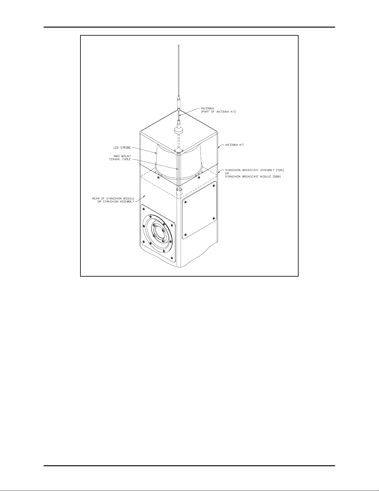
Figure 1.
Installation
Refer to Figure 2.
1. After installing the strobe, insert the NMO mount coaxial cable through the ¾ × 7/8-inch conduit
section at the top of the stanchion assembly or stanchion broadcast module. Allow the coaxial cable
to extend to the base of the stanchion. If using a stanchion broadcast module, the wires will also need
to be fed through the threaded nipple in the top of the existing stanchion.
2. Secure the lens cover onto the stanchion or stanchion module with the four tamper-resistant screws
provided with the stanchion. Be sure to place the seam of the lens cover to the rear of the stanchion.
3. App ly a s mall a mount of clea r RTV sil icon e sealant or equ ivalent to eac h screw threa d to re duce the
possibility of rust forming in the screw threads.
4. Screw the dual-band antenna onto the NMO mount on the top of the lens cover.
5. Attach the coaxial cable to the BNC connector on the 10458-xxx Electronics Paging Module. Refer
to the Paging Module Instructions contained in GAI-Tronics Pub. 42004-415.
f:\standard ioms - current releas e\ 42003 k it m anuals\42003-220a.doc
10/08
Page 3

Pub. 42003-220A
M
ODEL 12234-100 DUAL-BAND ANTENNA KIT Page: 3 of 3
Figure 2.
Replacement Parts
Part Numb e r Descrip tio n
GTRFP8585-021 Dual-Band Antenna, 150–174/450–470 MHz
f:\standard ioms - current releas e\ 42003 k it m anuals\42003-220a.doc
10/08
 Loading...