

Page 1

Pub. 42003-226A
GAI-TRONICS® CORPORATION
A HUBBELL COMPANY
I/O Termination Connection Module Kit
for LE200-RM
Model 12118-012
Confidential ity Notice
This manual is provided solely as an operational, installation, and maintenance guide and contains
sensitive business and technical information that is confidential and proprietary to GAI-Tronics.
GAI-Tronics retains all intellectual property and other rights in or to the information contained herein,
and such information may only be used in connection with the operation of your GAI-Tronics product or
system. This manual may not be disclosed in any form, in whole or in part, directly or indirectly, to any
third party.
General Information
The Model 12118-012 I/O Termination Connection Module Kit provides field wire termination for the
audio lines of the LE200-RM Rack-Mounted Line Extender. This kit includes the following components:
Qty Description
1 Line Extender I/O Termination Connection Module
1 DB25 Cable Assembly, 2.5-foot
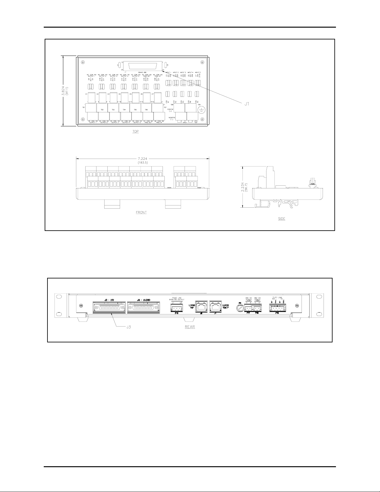
The connection module is DIN rail mountable and is mounted in the cabinet rack where the LE200-RM
Line Extender is installed. The DB25 cable assembly connects J1 of the Connection Module to J3 on the
rear of the LE200-RM. Field wiring of outputs is made to terminal blocks TB1 through TB7 and field
wiring of inputs is made to terminal blocks TB8 and TB9.
Installation
1. Snap the I/O Connection Module to the DIN rail within 2.5 feet of the LE200-RM Line Extender.
2. Plug one end of the DB25 cable assembly into J1 of the I/O Connection Module and secure it by
tightening the DB25 connector jackscrews. See Figure 1.
GAI-Tronics Corporation 400 E. Wyomissing Ave., Mohnton, PA 19540 USA
610-777-1374 800-492-1212 Fax: 610-796-5954
V
ISIT WWW.GAI-TRONICS.COM FOR PRODUCT LITERATURE AND MANUALS
Page 2
Pub. 42003-226A
ODEL 12118-012 CONNECTION MODULE KIT – I/O TERMINATION Page: 2 of 3
M
Figure 1. Line Extender Audio Termination Connection Module
3. Plug the other end of the DB25 cable assembly into J3 (I/O) on the rear of the LE200-RM Line
Extender as shown in Figure 2, and secure it by tightening the DB25 connector jackscrews.
Figure 2. LE200-RM Line Extender Rear Panel
4. Refer to Table 1 and Table 2 for field wiring connections to the I/O Connection Module.
5. Refer to the LE200-RM manual (GTC Pub. 42004-392) for additional operational information.
f:\standard ioms - current release\42003 kit manuals\42003-226a.doc
09/09
Page 3

Pub. 42003-226A
ODEL 12118-012 CONNECTION MODULE KIT – I/O TERMINATION Page: 3 of 3
M
Table 1. Auxiliary Input Connections
Terminal Designator Description
TB8 Input 1 (+)
Auxiliary input contact 1
TB8 Input 1 (-)
TB8 Input 2 (+)
Auxiliary input contact 2
TB8 Input 2 (-)
TB8 Input 3 (+)
Auxiliary input contact 3
TB8 Input 3 (-)
TB9 Input 4 (+)
Auxiliary input contact 4
TB9 Input 4 (-)
TB9 Input 5 (+)
Auxiliary input contact 5
TB9 Input 5 (-)
Table 2. Output Contact Connections
Designator Type Function
TB1 Terminal block Field connections for contact output 1.
The board’s silkscreen indicates the connections; the pin
numbers are not labeled.
TB2 Terminal block Field connections for contact output 2.
The board’s silkscreen indicates the connections; the pin
numbers are not labeled.
TB3 Terminal block Field connections for contact output 3.
The board’s silkscreen indicates the connections; the pin
numbers are not labeled.
TB4 Terminal block Field connections for contact output 4.
The board’s silkscreen indicates the connections; the pin
numbers are not labeled.
TB5 Terminal block Field connections for contact output 5.
The board’s silkscreen indicates the connections; the pin
numbers are not labeled.
TB6 Terminal block Field connections for page audio detected contact output.
The board’s silkscreen indicates the connections; the pin
numbers are not labeled.
TB7 Terminal block Field connections for page ground fault contact output.
The board’s silkscreen indicates the connections; the pin
numbers are not labeled.
f:\standard ioms - current release\42003 kit manuals\42003-226a.doc
09/09
Page 4

Warranty
Equipment. GAI-Tronics warrants for a period of one (1) year from the date of shipment, that any
GAI-Tronics equipment supplied hereunder shall be free of defects in material and workmanship, shall
comply with the then-current product specifications and product literature, and if applicable, shall be fit
for the purpose specified in the agreed-upon quotation or proposal document. If (a) Seller’s goods prove
to be defective in workmanship and/or material under normal and proper usage, or unfit for the purpose
specified and agreed upon, and (b) Buyer’s claim is made within the warranty period set forth above,
Buyer may return such goods to GAI-Tronics’ nearest depot repair facility, freight prepaid, at which time
they will be repaired or replaced, at Seller’s option, without charge to Buyer. Repair or replacement shall
be Buyer’s sole and exclusive remedy. The warranty period on any repaired or replacement equipment
shall be the greater of the ninety (90) day repair warranty or one (1) year from the date the original
equipment was shipped. In no event shall GAI-Tronics warranty obligations with respect to equipment
exceed 100% of the total cost of the equipment supplied hereunder. Buyer may also be entitled to the
manufacturer’s warranty on any third-party goods supplied by GAI-Tronics hereunder. The applicability
of any such third-party warranty will be determined by GAI-Tronics.
Services. Any services GAI-Tronics provides hereunder, whether directly or through subcontractors,
shall be performed in accordance with the standard of care with which such services are normally
provided in the industry. If the services fail to meet the applicable industry standard, GAI-Tronics will
re-perform such services at no cost to buyer to correct said deficiency to Company's satisfaction provided
any and all issues are identified prior to the demobilization of the Contractor’s personnel from the work
site. Re-performance of services shall be Buyer’s sole and exclusive remedy, and in no event shall GAITronics warranty obligations with respect to services exceed 100% of the total cost of the services
provided hereunder.
Warranty Periods. Every claim by Buyer alleging a defect in the goods and/or services provided
hereunder shall be deemed waived unless such claim is made in writing within the applicable warranty
periods as set forth above. Provided, however, that if the defect complained of is latent and not
discoverable within the above warranty periods, every claim arising on account of such latent defect shall
be deemed waived unless it is made in writing within a reasonable time after such latent defect is or
should have been discovered by Buyer.
Limitations / Exclusions. The warranties herein shall not apply to, and GAI-Tronics shall not be
responsible for, any damage to the goods or failure of the services supplied hereunder, to the extent
caused by Buyer’s neglect, failure to follow operational and maintenance procedures provided with the
equipment, or the use of technicians not specifically authorized by GAI-Tronics to maintain or service the
equipment. THE WARRANTIES AND REMEDIES CONTAINED HEREIN ARE IN LIEU OF AND
EXCLUDE ALL OTHER WARRANTIES AND REMEDIES, WHETHER EXPRESS OR IMPLIED BY
OPERATION OF LAW OR OTHERWISE, INCLUDING ANY WARRANTIES OF
MERCHANTABILITY OR FITNESS FOR A PARTICULAR PURPOSE.
Return Policy
If the equipment requires service, contact your Regional Service Center for a return authorization number
(RA#). Equipment should be shipped prepaid to GAI-Tronics with a return authorization number and a
purchase order number. If the equipment is under warranty, repairs or a replacement will be made in
accordance with the warranty policy set forth above. Please include a written explanation of all defects to
assist our technicians in their troubleshooting efforts.
Call 800-492-1212 (inside the USA) or 610-777-1374 (outside the USA) for help identifying the
Regional Service Center closest to you.
(Rev. 10/06)
 Loading...