

Page 1
Pub. 42004-740L2A
GAI-TRONICS® CORPORATION
A HUBBELL COMPANY
Model 13118-016
Modular TVP Barrier Assembly
Confidential ity Notice
This manual is provided solely as an operational, installation, and maintenance guide and contains sensitive
business and technical information that is confidential and proprietary to GAI-Tronics. GAI-Tronics
retains all intellectual property and other rights in or to the information contained herein, and such
information may only be used in connection with the operation of your GAI-Tronics product or system.
This manual may not be disclosed in any form, in whole or in part, directly or indirectly, to any third party.
General Information
Electrical and electronic systems and networks are subjected to disturbances from external sources of
electrical energy. These sources include electric power circuits and natural phenomena, such as lightning
and low energy static influences. Such disturbances may damage equipment and/or create hazards to
users and maintenance personnel.
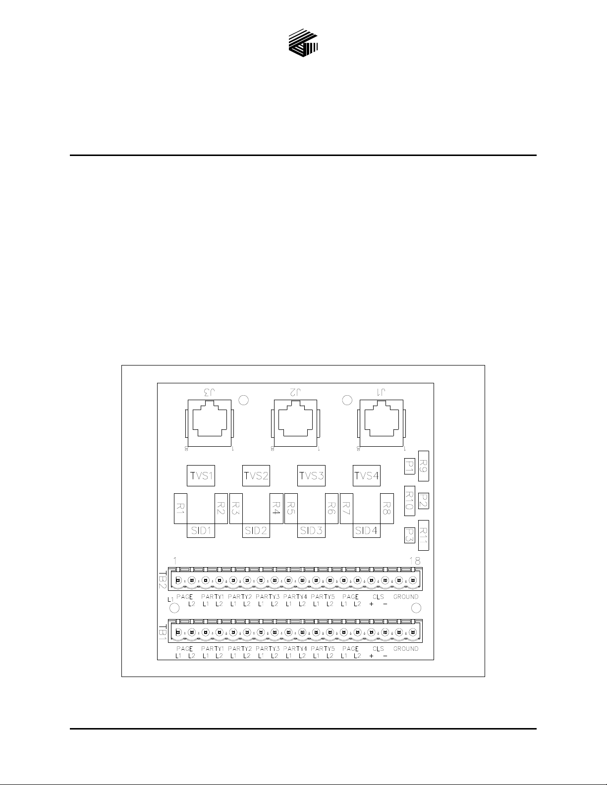
Figure 1. Model 13118-016 TVP Barrier Assembly
GAI-Tronics Corporation 400 E. Wyomissing Ave. Mohnton, PA 19540 USA
610-777-1374 800-492-1212 Fax: 610-796-5954
V
ISIT WWW.GAI-TRONICS.COM FOR PRODUCT LITERATURE AND MANUALS
Page 2

Pub. 42004-740L2A
Model 13118-016 Modular TVP Barrier Assembly Page 2 of 3
Applications
The Model 13118-016 Transient Voltage Protection (TVP) Barrier Assembly is designed to prevent
energy induced on the Page/Party
®
system cable from damaging the Page/Party® Interface (PPI) printed
circuit board assembly (PCBA). This assembly also allows party lines 3, 4 and 5 of the local zone to
connect with stations in other zones on the selected party line.
Connections
Table 1. Modular Terminal Blocks (TB1 & TB2) Field Wiring
Pin No.
1 Page Line – L1
2 Page Line – L2
3 Party Line 1 – L1
4 Party Line 1 – L2
5 Party Line 2 – L1
6 Party Line 2 – L2
7 Party Line 3 – L1
Function Remarks
The red/blue wire of the page pair contained within the Page/Party
cable is attached to this position of the terminal block.
The blue/red wire of the page pair contained within the Page/Party
cable is attached to this position of the terminal block.
The red wire of the party line #1 pair contained within the Page/Party
cable is attached to this position of the terminal block.
The tan/red wire of the party line #1 pair contained within the
Page/Party
The purple wire of the party line #2 pair contained within the
Page/Party
The tan/purple wire of the party line #2 pair contained within the
Page/Party
®
cable is attached to this position of the terminal block.
®
cable is attached to this position of the terminal block.
®
cable is attached to this position of the terminal block.
The blue wire of the party line #3 pair contained within the Page/Party
cable is attached to this position of the terminal block.
®
®
®
®
8 Party Line 3 – L2
9 Party Line 4 – L1
10 Party Line 4 – L2
11 Party Line 5 – L1
12 Party Line 5 – L2
The tan/blue wire of the party line #3 pair contained within the
Page/Party
The brown wire of the party line #4 pair contained within the
Page/Party
The tan/brown wire of the party line #4 pair contained within the
Page/Party
The yellow wire of the party line #5 pair contained within the
Page/Party
The tan/yellow wire of the party line #5 pair contained within the
Page/Party
®
cable is attached to this position of the terminal block.
®
cable is attached to this position of the terminal block.
®
cable is attached to this position of the terminal block.
®
cable is attached to this position of the terminal block.
®
cable is attached to this position of the terminal block.
13 Page Line – L1 No field connection (for internal use only)
14 Page Line – L2 No field connection (for internal use only)
15 CLS+
The spare orange wire contained within the Page/Party
attached to this position of the terminal block when All-Call control is
referenced to ground at field stations.
16 CLS−
This terminal is used with CLS+ when dry contact All-Call control is
employed at field stations via a separate pair of wires.
17 EGND Earth ground
18 EGND Earth ground
®
cable is
f:\standard ioms - current release\42004 instr. man uals\42004-740l2a.doc
04/13
Page 3

Pub. 42004-740L2A
Model 13118-016 Modular TVP Barrier Assembly Page 3 of 3
Installation
CAUTION
Safety Note: If GAI-Tronics Page/Party
®
cable is used, ensure the ac power conductors are disconnected
from any power source during the installation.
1. Snap the Modular TVP Barrier assembly onto one of the DIN mounting rails located in the cabinet.
®
2. Connect the appropriate Page/Party
mating plug provided. If the Page/Party
cable to modular terminal block TB1 per Table 1 using the
®
cable is looped, connect the "return" side of the cable to
TB2 per Table 1 using the mating plug provided.
3. Attach the appropriate Cat5E cable to the middle RJ45 jack (J2).
4. Attach a ground wire to TB1-17 or TB1-18.
5. If this module is replacing a damaged module, re-connect (plug-in) any cables to/from other modules
at J1 and/or J3.
6. Check and/or set positioning of the party line jumper clips P1 through P3 per the following table:
Table 2.
Jumper Clip Party Line Installed Removed
P1 3 Loaded (33-ohm) Un-loaded
P2 4 Loaded (33-ohm) Un-loaded
P3 5 Loaded (33-ohm) Un-loaded
*N
OTE: Factory default = All jumper clips installed.
Specification s
Mechanical
Dimensions ............................................................................................................. 4.00 H 4.00 W inches
Environmental
Temperature range ............................................................................................................ −30º C to +70º C
Humidity ........................................................................................ 95% non-condensing relative humidity
Reference to Assembly/Model Drawings
Published by Title GAI-Tronics Ref. No.
GAI-Tronics 13118-016 Modular TVP Barrier Assembly Drawing 13118-016
f:\standard ioms - current release\42004 instr. man uals\42004-740l2a.doc
04/13
Page 4

Warranty
Equipment. GAI-Tronics warrants for a period of one (1) year from the date of shipment, that any
GAI-Tronics equipment supplied hereunder shall be free of defects in material and workmanship, shall
comply with the then-current product specifications and product literature, and if applicable, shall be fit
for the purpose specified in the agreed upon quotation or proposal document. If (a) Seller’s goods prove
to be defective in workmanship and/or material under normal and proper usage, or unfit for the purpose
specified and agreed upon, and (b) Buyer’s claim is made within the warranty period set forth above,
Buyer may return such goods to GAI-Tronics nearest depot repair facility, freight prepaid, at which time
they will be repaired or replaced, at Seller’s option, without charge to Buyer. Repair or replacement shall
be Buyer’s sole and exclusive remedy. The warranty period on any repaired or replacement equipment
shall be the greater of the ninety (90) day repair warranty or one (1) year from the date the original
equipment was shipped. In no event shall GAI-Tronics warranty obligations with respect to equipment
exceed 100% of the total cost of the equipment supplied hereunder. Buyer may also be entitled to the
manufacturer’s warranty on any third-party goods supplied by GAI-Tronics hereunder. The applicability
of any such third-party warranty will be determined by GAI-Tronics.
Services. Any services GAI-Tronics provides hereunder, whether directly or through subcontractors,
shall be performed in accordance with the standard of care with which such services are normally
provided in the industry. If the services fail to meet the applicable industry standard, GAI-Tronics will reperform such services at no cost to buyer to correct said deficiency to Company's satisfaction provided
any and all issues are identified prior to the demobilization of the Contractor's personnel from the work
site. Re-performance of services shall be Buyer's sole and exclusive remedy, and in no event shall GAITronics warranty obligations with respect to services exceed 100% of the total cost of the services
provided hereunder.
Warranty Periods. Every claim by Buyer alleging a defect in the goods and/or services provided
hereunder shall be deemed waived unless such claim is made in writing within the applicable warranty
periods as set forth above. Provided, however, that if the defect complained of is latent and not
discoverable within the above warranty periods, every claim arising on account of such latent defect shall
be deemed waived unless it is made in writing within a reasonable time after such latent defect is or
should have been discovered by Buyer.
Limitations / Exclusions. The warranties herein shall not apply to, and GAI-Tronics shall not be
responsible for, any damage to the goods or failure of the services supplied hereunder, to the extent
caused by Buyer’s neglect, failure to follow operational and maintenance procedures provided with the
equipment, or the use of technicians not specifically authorized by GAI-Tronics to maintain or service the
equipment. THE WARRANTIES AND REMEDIES CONTAINED HEREIN ARE IN LIEU OF AND
EXCLUDE ALL OTHER WARRANTIES AND REMEDIES, WHETHER EXPRESS OR IMPLIED BY
OPERATION OF LAW OR OTHERWISE, INCLUDING ANY WARRANTIES OF
MERCHANTABILITY OR FITNESS FOR A PARTICULAR PURPOSE.
Return Policy
If the equipment requires service, contact your Regional Service Center for a return authorization number
(RA#). Equipment should be shipped prepaid to GAI-Tronics with a return authorization number and a
purchase order number. If the equipment is under warranty, repairs or a replacement will be made in
accordance with the warranty policy set forth above. Please include a written explanation of all defects to
assist our technicians in their troubleshooting efforts.
Call 800-492-1212 (inside the USA) or 610-777-1374 (outside the USA) for help identifying the
Regional Service Center closest to you.
(Rev. 10/06)
 Loading...